Poor quality gears

Advert

Poor quality gears

Home Forums I/C Engines Poor quality gears

Viewing 23 posts - 26 through 48 (of 48 total)
  • Author
    Posts
  • #196616
    Ajohnw
    Participant
      @ajohnw51620
      Posted by Bazyle on 12/07/2015 14:47:15:

      I'm having trouble thinking of any machining method that would leave such marks. There don't seem to be traces of marks from a regular hob or a cnc endmill process going awry. It looks more like they were cleaned up by shot blasting with small bearings.

      I suspect that they have been made on a gear shaper and maybe the gears that make up the linkage for rotating the blank etc are a bit worn. If a shaper is used the same rack form can cut any gear of it's dp / mod. If the usual disk type form cutters are used there are added complications for precise work.

      Personally I would just clean them up the marks are just cosmetic. They could be checked out by running them together with a thin smear of blue. I wonder if Reeves of old in Marston Green sourced better gears. They ran into grief due to certain people producing investment castings etc that just needed cleaning up with a file. On the other hand perhaps interest in the hobby was dropping off as well.

      If lapped thinking a bit more about the problem it would be better to advance the tooth mesh by a prime number not associated with the gear tooth counts and not 1. 5 might be a suitable number but I suspect you will run into grief lapping the small one against the larger one.

      John

      Edited By John W1 on 13/07/2015 11:33:57

      Edited By John W1 on 13/07/2015 11:34:21

      Advert
      #196625
      JasonB
      Moderator
        @jasonb

        As they are only timing gears on a slow running engine I'm sure they will be fine as is like Rod says.

        Not sure what your supplier charges for the set but for just over £20 you could get 13/26 32DP gears from HPC which come close to teh original 7/8" ctrs at 0.862" and for a small extra charge they will make the wider width if you prefer to stick with te drawn width rather than add a spacer.

        #196627
        MichaelR
        Participant
          @michaelr

          As Jason says the HPC gears will do the job, I have them on my Centaur and they don't alter the valve gear settings.

          Mike. hpc gears.jpg

          #196629
          Ajohnw
          Participant
            @ajohnw51620

            Haven't checked but there might also be something here. HPC seems to be the obvious choice.

            **LINK**

            There are a number of USA on line retailers even offering stainless. They seem to refer to them as screw gears when crossed. Helical otherwise.

            The book I mentioned is by Brown & Sharp. A Practical Treatise on Milling dated 1930. They introduce lead by wrapping a right angle triangle around a cylinder and from that introduce the angle. Some parts are confusing such as the lead changing as the diameter of the gear changes suggesting that any ratio other than 1:1 will have different leads – then follow with a statement that suggests they need to be the same. It does discuss a number of complications about the use of the usual form cutters on helical gears caused by the fact that they are effectively a thread. The cutter choice and cut departs from the correct one for the DP due to that.

            winkThere used to be a lot of books like this in older junk shop type used book shops around in B'ham. I'd guess most have been burnt now.

            Whoops – on Milling should read on Gearing.

            John

            Edited By John W1 on 13/07/2015 14:16:22

            #196637
            Neil Wyatt
            Moderator
              @neilwyatt

              To my eye, that gear appears cast rather than machined. If so it should be rather cheaper than a machined gear.

              If it's cast and it meshes and it is cheaper than a machined gear, I would be inclined to accept it – I'm sure it will survive in fitted to a light-duty 19cc engine.

              Neil

              #196639
              JasonB
              Moderator
                @jasonb

                56cc Neil 1.5" bore x 2" stroke

                #196640
                Ajohnw
                Participant
                  @ajohnw51620

                  Going back to Rod's post on designing screw gears this may be of interest AND FREE till some one notices it, removes it and sells it as an e-book.

                  **LINK**

                  The problem with the site is how easy it is to waste an hour or so seeing what's there on a particular subject.

                  John

                  #196643
                  Neil Wyatt
                  Moderator
                    @neilwyatt
                    Posted by JasonB on 13/07/2015 17:40:16:

                    56cc Neil 1.5" bore x 2" stroke

                    The OP is talking about Centaur (1" x 1 3/4&quot not Wyvern.

                    Neil

                    #196647
                    Roderick Jenkins
                    Participant
                      @roderickjenkins93242

                      Sorry, I confused the issue by introducing Wyvern into the conversation but Jason's correct – Centaur, the bigger engine, is 1.5" x 2".

                      Rod

                      #196650
                      Roderick Jenkins
                      Participant
                        @roderickjenkins93242
                        Posted by John W1 on 13/07/2015 17:41:32:

                        Going back to Rod's post on designing screw gears this may be of interest AND FREE till some one notices it, removes it and sells it as an e-book.

                        **LINK**

                        That's very useful – downloaded and saved. Interesting to see the derivation of the calculation for selecting the cutter. My copy of Machnery's Handbook (25) gives an additional calculation for choosing the correct cutter which takes the diameter of the gear cutter into account. The problem with this is that one quickly runs out of cutters. Standard sets stop at 135 teeth and above but the selector calculation can call for cutters for e.g.250 teeth. My solution is to use the simple calculation if you're making a matching set of gears but it is probably best to use the more exact method if your making a gear to fit with an existing hobbed gear.

                        I've put the calculations in a spreadsheet here **LINK**

                        Rod

                        PS.  I should point out that I've used the odd size of 31.75 DP in the spreadsheet because it's 0.8 MOD and HSS MOD cutters are readily (and cheaply) available from the far east.

                        Edited By Roderick Jenkins on 13/07/2015 18:29:38

                        #196653
                        Michael Gilligan
                        Participant
                          @michaelgilligan61133
                          Posted by John W1 on 13/07/2015 17:41:32:

                          … AND FREE till some one notices it, removes it and sells it as an e-book.

                          **LINK**

                          .

                          John,

                          Thanks for the link star

                          I don't think you need to worry too much about the Internet Archive:

                          although Google [for some, presumably commercial, reason] does seem to have adopted the nasty habit of claiming that there is "no eBook available" if you follow the links to their site.

                          The answer is use the "show all files" link on the Internet Archive page. < example >

                          MichaelG.


                          Edited By Michael Gilligan on 13/07/2015 19:41:22

                          #196658
                          Neil Wyatt
                          Moderator
                            @neilwyatt
                            Posted by Roderick Jenkins on 13/07/2015 18:07:42:

                            Sorry, I confused the issue by introducing Wyvern into the conversation but Jason's correct – Centaur, the bigger engine, is 1.5" x 2".

                            Rod

                            I'm confused even more now. Reeves' website gives Centaur as 1 x 1 1/2"

                            Neil

                            #196659
                            JasonB
                            Moderator
                              @jasonb
                              Posted by Neil Wyatt on 13/07/2015 19:54:56:

                              Posted by Roderick Jenkins on 13/07/2015 18:07:42:

                              Sorry, I confused the issue by introducing Wyvern into the conversation but Jason's correct – Centaur, the bigger engine, is 1.5" x 2".

                              Rod

                              I'm confused even more now. Reeves' website gives Centaur as 1 x 1 1/2"

                              Neil

                              You don't want to believe everything you read on the netwink 2

                              cent1.jpg

                              cent2.jpg

                              #196662
                              Ajohnw
                              Participant
                                @ajohnw51620
                                Posted by Michael Gilligan on 13/07/2015 19:36:48:

                                Posted by John W1 on 13/07/2015 17:41:32:

                                … AND FREE till some one notices it, removes it and sells it as an e-book.

                                **LINK**

                                .

                                John,

                                Thanks for the link star

                                I don't think you need to worry too much about the Internet Archive:

                                although Google [for some, presumably commercial, reason] does seem to have adopted the nasty habit of claiming that there is "no eBook available" if you follow the links to their site.

                                The answer is use the "show all files" link on the Internet Archive page. < example >

                                MichaelG.

                                Edited By Michael Gilligan on 13/07/2015 19:41:22

                                I knew about the show all files but haven't had to use it on the new layout they use but should do really to get the djvu files as they are much smaller and just as good as pdf's if scanned correctly. Searches also work on these. They don't for me on scanned pdf's on Linux. Not sure about Windows.

                                What has a happened in a few instances is that archive downloads have disappeared and are only available as e-books or prints of them that have to be paid for. As the copyrights have often lapsed by rather a long time I wonder how this happens. I suspect it's just the threat of legal action when there isn't really any basis.

                                Noticing the comments about cheaper gear cutters for ordinary spur gears there are some cheaper hobs about now. I recently noticed that a 2mod hob has a cp of 0.2474 so close to 0.250 that a bit of lapping would soon make a worm mesh correctly with a wheel. i feel gashed wheels are fine for home use for dividing etc so bought a Russian one very cheaply. Just a little more than one from China. My dividing head is the one designed for the Dore Westbury and I sometime get tempted to try something a bit larger. On the other hand the worms and wheels for dividing head kits aren't too badly priced really.

                                John

                                #196697
                                bricky
                                Participant
                                  @bricky

                                  I have just obtained the full set of castings from Reeves for the Centaur gas engine.I had not unpacked all of them so after reading this post I checked the supplied gears and found them to be excellent,nothing like those shown.I think that they had a bad batch.

                                  Frank

                                  #196917
                                  Anonymous

                                    Right, second attempt after I hit the 'wrong' key sequence and lost everything I had typed. angry 2

                                    Out of curiousity I had a quick run through the design steps for helical gears as shown in Machinery's Handbook last night. It all seems pretty straightforward.

                                    The key is appreciating that there are two diametric pitches (DP), one in the plane of rotation, as per spur gears, and a normal DP perpendicular to the helix angle. The normal DP is generally used for design purposes, and if it is made an integer then standard involute cutters can be used.

                                    There are, of course, some complications. First, even for a fixed normal DP and number of teeth, the pitch circle diameter, and outside diameter (OD), vary with the helix angle. Hence the centre to centre distance of a given pair of gears will vary with helix angle. That is why there are different design flows in Machinery's Handbook depending on whether the centre to centre distance is fixed or flexible.

                                    The choice of helix angle is also flexible. For parallel shafts, as for spur gears, the angle is largely arbitrary. It seems to be chosen just large enough to ensure that a second pair of teeth engage before the previous pair disengage. This should promote smoother high speed running, which is one reason for using helical gears, as opposed to spur gears, in the first place. For non-parallel shafts there is a constraint on the helix angles. The sum of the helix angles of the two gears must add up to the angle between the shafts. So for the engine mentioned by the OP, where the shafts are at 90º then the helix angles should add up to 90º. Presumably 45º each would be logical?

                                    There are probably two approaches to machining helical gears in the normal home workshop. Either a universal mill (see note 1) and universal dividing head, or a 4-axis CNC mill in conjunction with software such as Gearotic. Using a universal mill has some limitations. Most tables only swivel ±45º so for cutting steeper helix angles a special swivelling vertical head is required. I don't have one of these; I'm trying to visualise if it would be possible to machine steeper helix angles by setting the dividing head at an angle and using a one axis swivelling head, which I do have. Another potential issue is the range of leads available with the gears supplied with the dividing head. The lead is the distance travelled by the helix over one rotation. If the lead required does not exactly match those provided then an error will result. Whether the error is significant will depend on the application and the width of the gear. If the error is unacceptable it is possible to calculate a gear train for greater accuracy, but this would normally require custom gears for the drive train from table to dividing head.

                                    Back to work now!

                                    Andrew

                                    Note 1: It is one of many model engineering myths that a universal mill is one that has horizontal and vertical capability. Not so, it is a mill that has a swivelling table so that in conjunction with a universal dividing head, that can be driven from the table, it can be used to machine helical paths for things like helical gears or flutes on special tooling.

                                    Edited By Andrew Johnston on 16/07/2015 12:12:26

                                    #196924
                                    Ajohnw
                                    Participant
                                      @ajohnw51620

                                      I mentioned the advantage of a true universal mill to some one recently on here who was lusting after a Bridgeport. Trouble is though finding one that has the gear with it and is in good order. Some of the smaller ones are also surprisingly heavy and are likely to be odd not well known makes with what seem to be rather large motors.

                                      The brown and sharp book I have and mentioned is also on the archive, several versions of it. One thing it adds is the best route to designing a set up and why. For other aspects the book I linked to in my opinion is a lot clearer. Just search gearing.

                                      John

                                      #196925
                                      Roderick Jenkins
                                      Participant
                                        @roderickjenkins93242

                                        Posted by Andrew Johnston on 16/07/2015 12:08:22:. So for the engine mentioned by the OP, where the shafts are at 90º then the helix angles should add up to 90º. Presumably 45º each would be logical?

                                        By making the 2 gears the same OD using 60 and 30 degrees it is possible to contain them in a smaller envelope which is , perhaps, why ETW favoured them.

                                        There are probably two approaches to machining helical gears in the normal home workshop. Either a universal mill (see note 1) and universal dividing head, or a 4-axis CNC mill in conjunction with software such as Gearotic.

                                        Your normal home workshop is a bit bigger than minewink . A milling spindle on a swiveling vertical slide provides the same functionality:

                                        gear 8.jpg

                                        Neil's Potts could have a use!

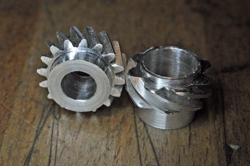
                                        A pair of trial 32 DP 60 and 30 degree gears in ally (actually 31.75DP = 0.8MOD)

                                        gear 9.jpg

                                        Cheers,

                                        Rod

                                        #196933
                                        Anonymous
                                          Posted by Roderick Jenkins on 16/07/2015 13:31:50

                                          Your normal home workshop is a bit bigger than minewink . A milling spindle on a swiveling vertical slide provides the same functionality:

                                          Very possibly, but I suspect that my universal mill and dividing head may have cost less than a Myford swivelling vertical slide and milling spindle judging by some of the prices on the internet. thumbs up

                                          Your gears look good. Presumably the milling spindle is swivelled to the helix angle and the leadscrew gear train is set up to provide the appropriate rotation of the spindle for a given saddle movement. Is the cut applied by turning the leadscrew handle? When it comes to indexing each tooth presumably the gear train is disconnected, the spindle moved an appropriate number of teeth and the gear train reconnected? Always assuming of course that the number of teeth required is a factor somewhere in the gear train.

                                          I don't follow the 30º and 60º helix angles for the same OD. Presumably if the OD of the two gears is the same then the PCD will also be the same for both gears? I am assuming that the number of teeth is in the ratio 2:1. The PCD is given by the number of teeth divided by the product of the normal DP and the cosine of the helix angle. So if I've done my maths correctly twice the cosine of the larger angle (on the gear with fewer teeth) should equal the cosine of the helix angle on the gear with the smaller angle. That does not seem to be the case for 30º and 60º. I've no doubt that I am making a prat of myself over this by missing something obvious, but hey, I should learn something from it.

                                          Even if it is only shutup and don't post nonsense. sad

                                          Andrew

                                          #196936
                                          Roderick Jenkins
                                          Participant
                                            @roderickjenkins93242

                                            Andrew,

                                            Sorry, I have misled you slightly – the angles for identical PCD (2:1 ratio) are 26.6 degrees and 63.4 degrees but 60 and 30 is as close as you can (sometimes) get from stock gears. PCD is, as you say, number of teeth N / (DP x COS (a)). so for 32 DP 16T 30 degrees PCD is .577" and for 8T 60 degrees .500". Quite close: They are identical for the "magic" angles.

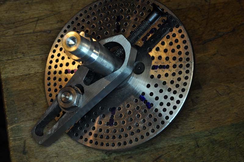
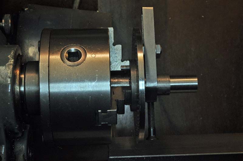
                                            You are quite correct about the technique for machining except that I mounted the blank in a collet in the 3 jaw with a dividing plate mounted on it and an indexer fastened, lathe carrier style, to the blank.

                                            gear 7.jpg

                                            gear 3.jpg

                                            I'm sure you are correct about the relative equipment costs but possibly nullified by the need to move to a bigger house – my traction engine is going to be just the one MInnie smiley

                                            Cheers,

                                            Rod

                                            #196963
                                            Anonymous

                                              Rod: Ah, that's neat putting the dividing head on the spindle. I'm relieved that my maths isn't completely out of order. While waiting for supper to cook earlier I thought I'd have a go at solving the problem analytically. For those that can't be bothered to do the maths here is my solution:

                                              helical_maths.jpg

                                              I make the PCD of the gears, with the precise angles, equal to 0.559". That gives leads of 3.5123" (89.217mm) and 0.8781" (22.303mm). From the tables for my dividing head the nearest leads with standard gears are 89.30mm and 22.32mm – it's a metric mill. I reckon that gives errrors of 0.9µm and 0.7µm per millimetre of face width. That's pretty small and certainly good enough for skew gears. In practise these relatively short leads would require a significant step up ratio in the gearing, so the dividing head spindle would be better driven directly from the table rather than through the worm reduction in the dividing head.

                                              To be precise the universal mill was £145 and the dividing head £125. One would need a pretty solid workshop for the mill, it weighs around 3500lbs, has 5hp motor and knocks the Bridgeport into a cocked hat when it comes to rigidity and simply ploughing through metal like it wasn't there. I've learnt the hard way that you really need to clamp the work down properly.

                                              Andrew

                                              #196968
                                              Roderick Jenkins
                                              Participant
                                                @roderickjenkins93242

                                                Well done. Nice to see it done properly! I'm afraid I resort to a spreadsheet driven iterative process for this sort of things these days.

                                                Rod

                                                #196974
                                                Muzzer
                                                Participant
                                                  @muzzer

                                                  Andrew – you can cut out the stuff in the middle and combine lines 1 and 2 directly, giving:

                                                  2 Cos(90-a1) = Cos(a1)

                                                  but Cos(90-a1) = Sin(a1)

                                                  So line 1 becomes 2Sin(a1) = Cos(a1),

                                                  ie Tan(a1) = 1/2.

                                                  (The mixed blessing of having children of secondary school age)

                                                  Still don't understand the gear stuff though!

                                                  Murray

                                                  Edited By Muzzer on 16/07/2015 22:29:58

                                                Viewing 23 posts - 26 through 48 (of 48 total)
                                                • Please log in to reply to this topic. Registering is free and easy using the links on the menu at the top of this page.

                                                Advert

                                                Latest Replies

                                                Home Forums I/C Engines Topics

                                                Viewing 25 topics - 1 through 25 (of 25 total)
                                                Viewing 25 topics - 1 through 25 (of 25 total)

                                                View full reply list.

                                                Advert

                                                Newsletter Sign-up