piezzo buzzer

Advert

piezzo buzzer

Home Forums Electronics in the Workshop piezzo buzzer

Viewing 17 posts - 1 through 17 (of 17 total)
  • Author
    Posts
  • #32249
    duncan webster 1
    Participant
      @duncanwebster1
      Advert
      #593247
      duncan webster 1
      Participant
        @duncanwebster1

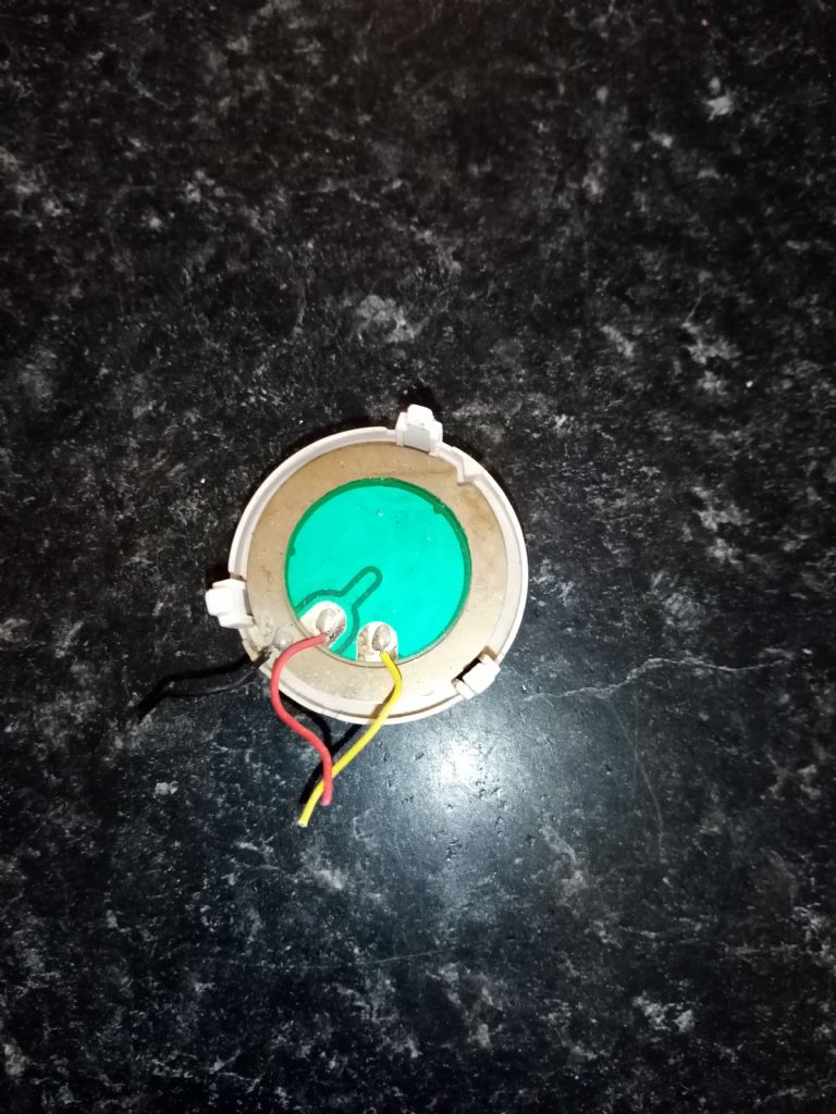
        I've recovered this from a smoke alarm, it looks as tho I have to give it some ac signal, or at least pulsed dc. Before I release the magic smoke anyone know which wire is which? Can I drive it straight off an Arduino, or will it need a drive transistor?

        img_20220406_182608.jpg

        #593250
        Jeff Dayman
        Participant
          @jeffdayman43397

          Kyocera and Murata were two big names in piezoceramics when I was involved with them (mechanical mounting) for smoke alarms many years ago. A link below to Kyocera, who may be able to help with info / datasheets.

          https://global.kyocera.com/prdct/ecd/piezo_single/index.html

          #593252
          AJAX
          Participant
            @ajax
            #593257
            SillyOldDuffer
            Moderator
              @sillyoldduffer

              I'd connect black to ground and yellow to the Arduino via a 1k resistor.

              As they resonate at particular frequency (so the Arduino's output will have to be tuned to match), to avoid blowing the Arduino's output, I'd assume it's a short circuit. 1k-ish will protect it. Might be OK without because Arduino can do 30mA out, but safer not to risk it. A scope would reveal how much 1k drops the 5V line, hence allowing the current to be calculated. I'd adjust R for 20mA to give max safe noise, you might think that's conservative.

              Dave

              #593263
              duncan webster 1
              Participant
                @duncanwebster1

                Thanks, I'll give it a go and report back, if I haven't destroyed my hearing (what's left of it)

                #594166
                duncan webster 1
                Participant
                  @duncanwebster1

                  Hearing undamaged, as it made no sound at all. Tried a 64 ohm speaker with suitable dropper resistance just to make sure I had some output, so I've freed up some storage space and binned the piezzo.

                  #594174
                  Joseph Noci 1
                  Participant
                    @josephnoci1

                    Gound to the brass disk, signal to the broad plated area. NO resistor in series…Fed direct from Arduino output. These buzzers work well at higher voltages – 10 to 30volts Ac, and must be at the resonant frequency for any useful sound. The one you have ( had..) when used in a single transistor oscillator with a 8 to 10 millihenry coil as resonating inductor – will buzz loudly with a 5volt supply and a scope will show a good 20 or so volts across the piezo – result of resonance of the piezo disc capacitance and the inductor. A straight 5volt sq wave to the piezo from the Arduino would have made sound if at resonance. Just using a audio signal genny with a 5v output sweeping across resonance made my buzzer whistle nicely…soft but definite.

                    #594176
                    brian roberts 2
                    Participant
                      @brianroberts2

                      Duncan,

                      Perhaps the piezo buzzer has too high a frequency ?

                      I know in my own case that age-related hearing loss (too much DIY drilling and motorcycling perhaps) and tinnitus have wreaked havoc with hearing higher frequencies.

                      These young designers may be accomplished, but they never ask us old 'uns if we can hear / see/ operate their micro-miniature marvels.

                      Progress I suppose ?

                      #594179
                      Joseph Noci 1
                      Participant
                        @josephnoci1

                        20mm OD discs are around 6-7kHz, 27mm discs around 3.2-3.7kHz, so your hearing must be really messed to not hear those frequencies – most unlikely.

                        #594182
                        duncan webster 1
                        Participant
                          @duncanwebster1

                          Tried feeding it from a sig gen via open collector transistor, piezzo from +ve to collector. I connected +5 to where the yellow wire is on above photo and collector to where black wire is. Still no joy, so wound up the volts to 9v, still nowt. I can hear the little speaker, so not my hearing, although it does get quite challenged above 6kHz. My excuse is it's a devensive mechanism, women have higher pitched voices.

                          #594192
                          Huub
                          Participant
                            @huub

                            There are a lot of Arduino example projects for a piezo buzzer.

                            Arduino piezo buzzer example

                            #594202
                            Joseph Noci 1
                            Participant
                              @josephnoci1

                              Either the Piezo is duff or the transistor is duff or not being turned on Duncan. Knowing what you dabble with, I am sure you took care of sufficient drive to the Base, via series resistor to the base…1K or so…

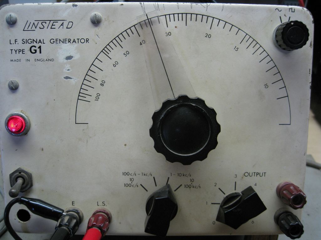
                              I used an old Linstead English Valve audio gen to do this..

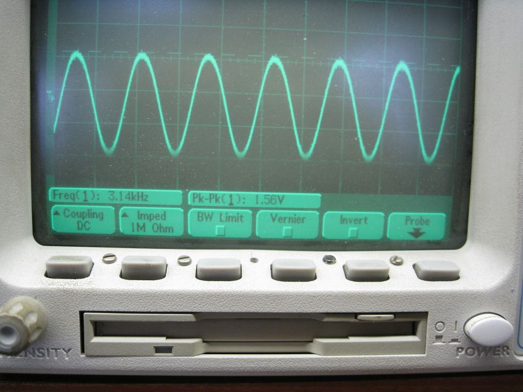
                              Sig Gen set to 1-10kc/s (!) range, output set very low – 1.56v PK-PK on the scope – Freq at resonance approx 3Khz.

                              img_0616.jpg


                              img_0620.jpg


                              Check the video and its noise…

                              EDIT – Square wave setting on sig gen resulted in maybe 50% drop in perceived sound amplitude – PK-PK voltage was the same as the sine setting on the 'scope. Also tried the OC transistor – it did not work –  when the transistor turns off, the voltage across the disc remains – there is no discharge / reversal so the piezo does nothing – it cannot bend opposite as there is no voltage plus/minus swap – the next transistor turn on just replenishes the charge on the piezo. ( like charging a capacitor, since that is what it is..)

                              Its not like a voice coil speaker which has a mechanical spring built in to return it to a zero position ( the cone, etc).  The peizo element is a high impedance, except at resonance, and a charge applied is maintained for some time – it dissipates  slowly compared to the period of resonance, so the piezo remains 'bent' in one direction, till you discharge it, charge it in opposition, or leave it for some |miliseconds| …

                              Edited By Joseph Noci 1 on 13/04/2022 08:06:12

                              #594214
                              Samsaranda
                              Participant
                                @samsaranda

                                Duncan I have a severe high frequency hearing loss and used the “women have high pitched voices” with my wife, the scars have just about healed ! Dave W

                                #594309
                                duncan webster 1
                                Participant
                                  @duncanwebster1

                                  Thanks Joe, now I understand. The signal generator I was using is just a 555 with an output transistor to make it OC. What I've tried now is 100 ohm from +ve to collector and piezzo from collector to ground. That works, but at only one frequency, very narrow band.

                                  When the muse strikes again I'll have a go at the circuit in Ajax's link, no choke required

                                  #594326
                                  Joseph Noci 1
                                  Participant
                                    @josephnoci1

                                    Why do you wish to use the OC setup? The 555 output is a totem pole driver – drives Hi and Lo – just connect the Piezo directly from pin 3 to ground – no resistor, etc. At 12v supply to the 555 that piezo should be loud. Also, for max loudness, the disc should be flexibly supported ( on the brass side) at the piezo diameter – for your testing, just place the disc brass side down on an O ring of OD = the piezo diameter – approx…

                                    Just some things WRT the 555 timer – it's not simple to use it as a variable frequency gen if you wish to have the resulting waveform have a 1:1 mark/space ratio. That's because the conventional astable circuit charges the cap through both resistors, but discharges it through only one of them. So if you are varying the frequency by changing only one of the two resistors, the frequency AND mark/space changes. The result is that the piezo sees a greater voltage of one polarity than the opposing polarity, ie, it is biased to 'bend' more one way, and stay bent more in that direction – so the amplitude is reduced …

                                    You can calculate the two R values to have 1:1 ratios at ONE frequency only – Equal value R's give a 2:1 ratio..


                                    Ajax's post is the typical self-oscillating cct – place a 8-10mH inductor from collector to +ve supply ( instead of the resistor) and the cct makes a big noise, even at 2V DC supply!

                                    Edited By Joseph Noci 1 on 13/04/2022 21:44:54

                                    #594331
                                    duncan webster 1
                                    Participant
                                      @duncanwebster1

                                      I used the 555/OC because I had it, made years ago. It has OC output so that it doesn't send voltage to whatever is connected to it. The 555 has an odd circuit I found where the timing cap is connected to the output via a resistor and so charge/discharge is via the same resistor. I think this means equal mark/space. It was a lot better than nothing at the time.

                                    Viewing 17 posts - 1 through 17 (of 17 total)
                                    • Please log in to reply to this topic. Registering is free and easy using the links on the menu at the top of this page.

                                    Advert

                                    Latest Replies

                                    Viewing 25 topics - 1 through 25 (of 25 total)
                                    Viewing 25 topics - 1 through 25 (of 25 total)

                                    View full reply list.

                                    Advert

                                    Newsletter Sign-up