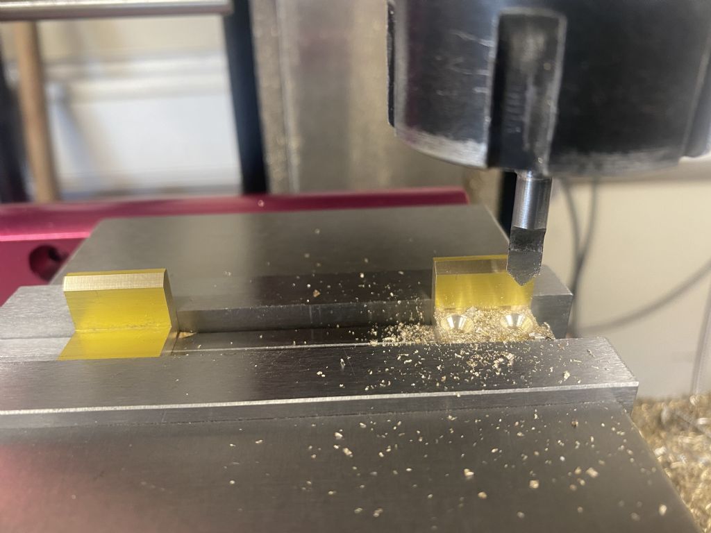
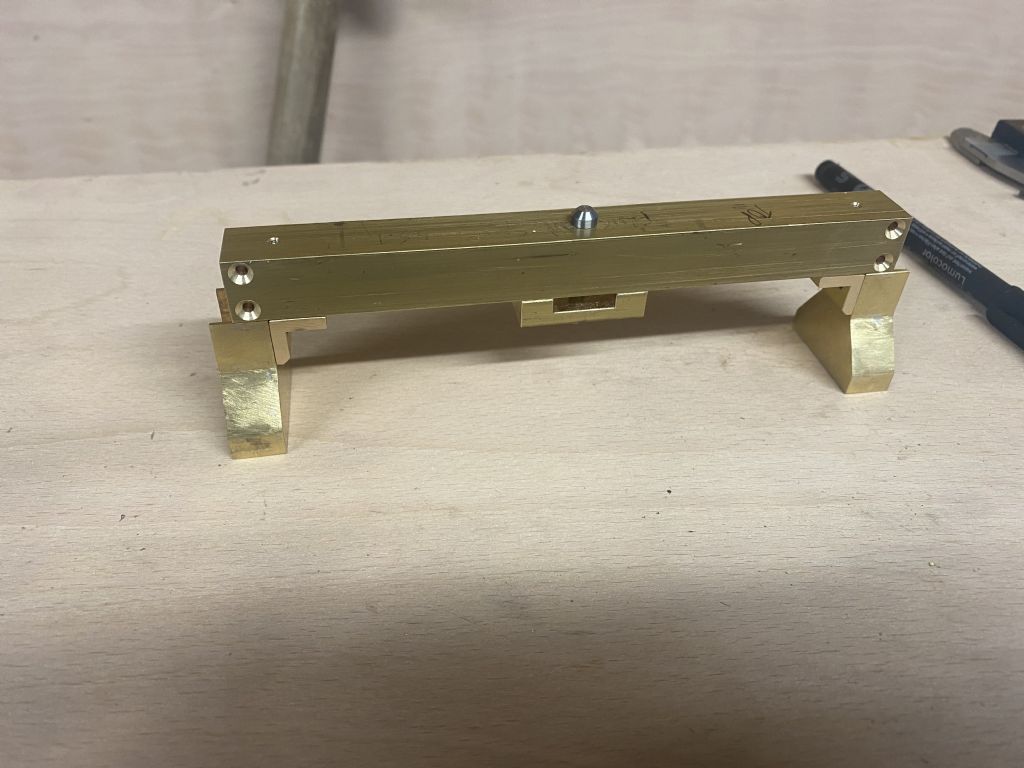
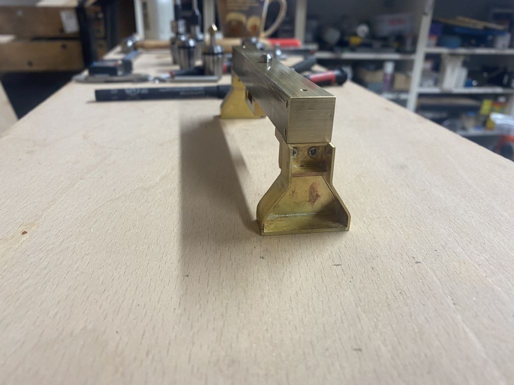
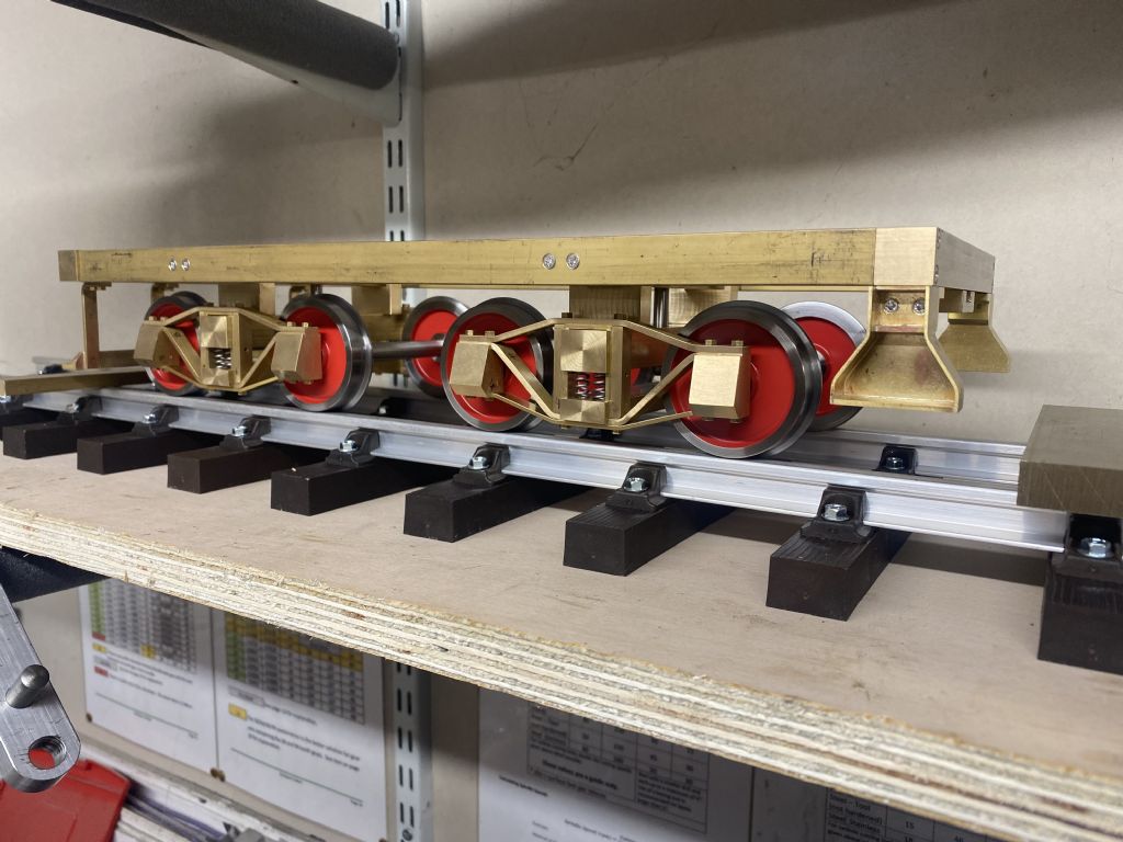
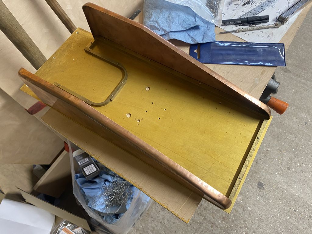
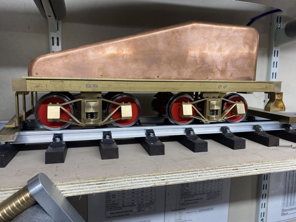
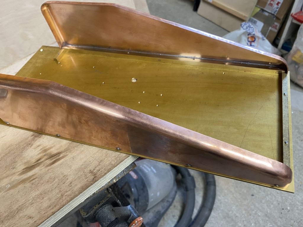
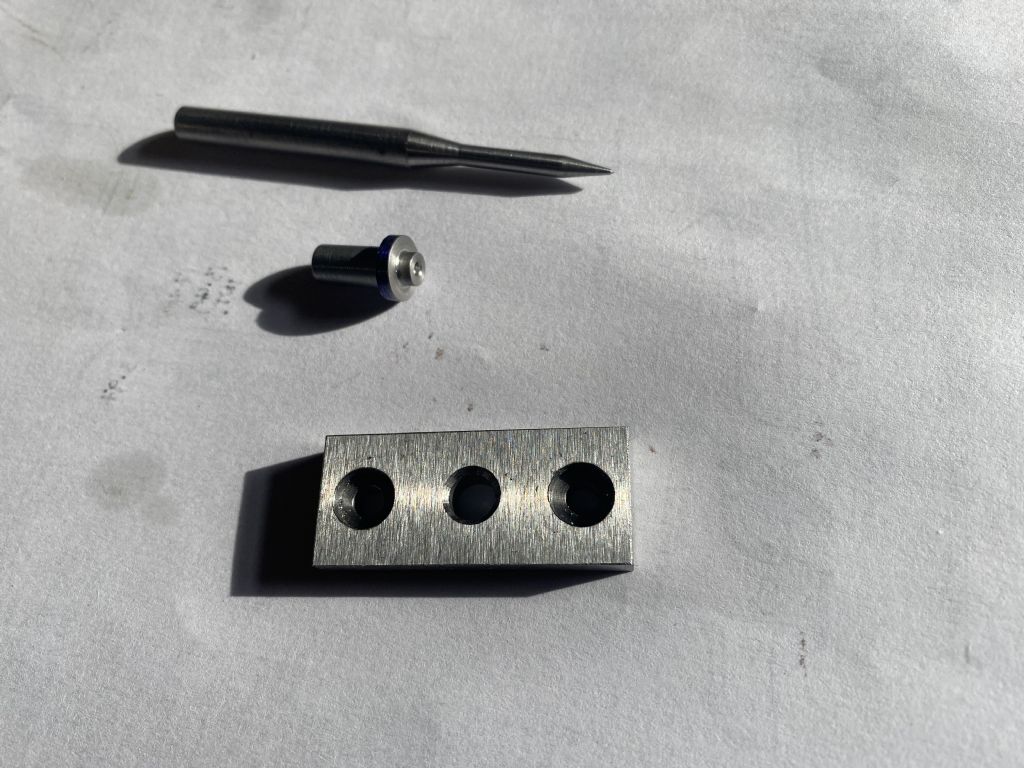
I also made up the little brackets to hold the front steps:
I had to make up that D bit as even my smallest countersink wouldn't fit
With that, the front end is complete, just the freehand filing to do…..
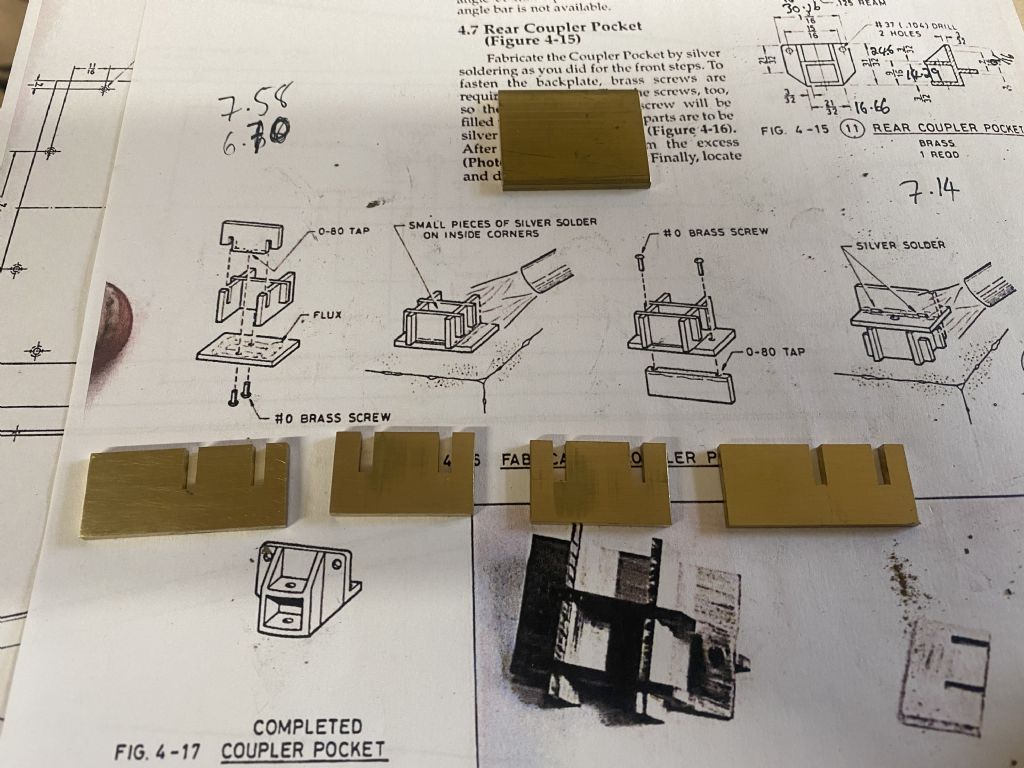
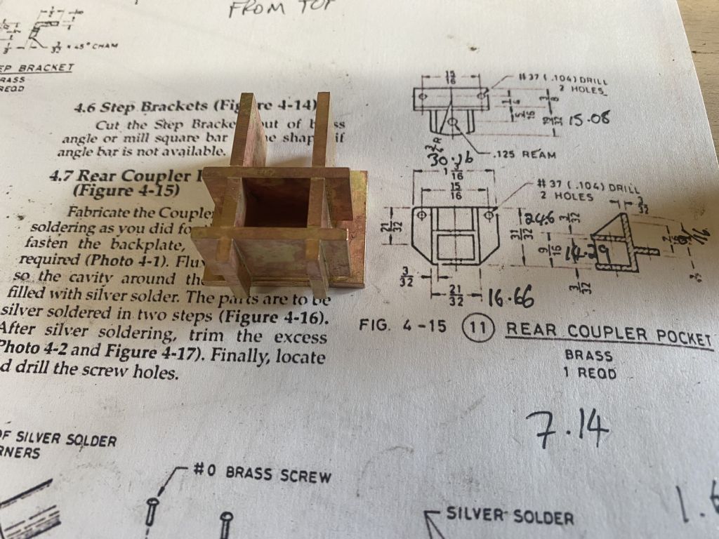
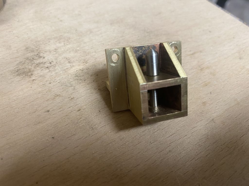
I then got on and made up the rear coupler pocket:
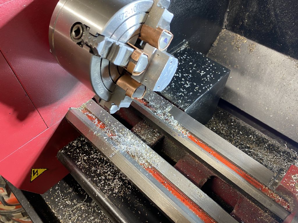
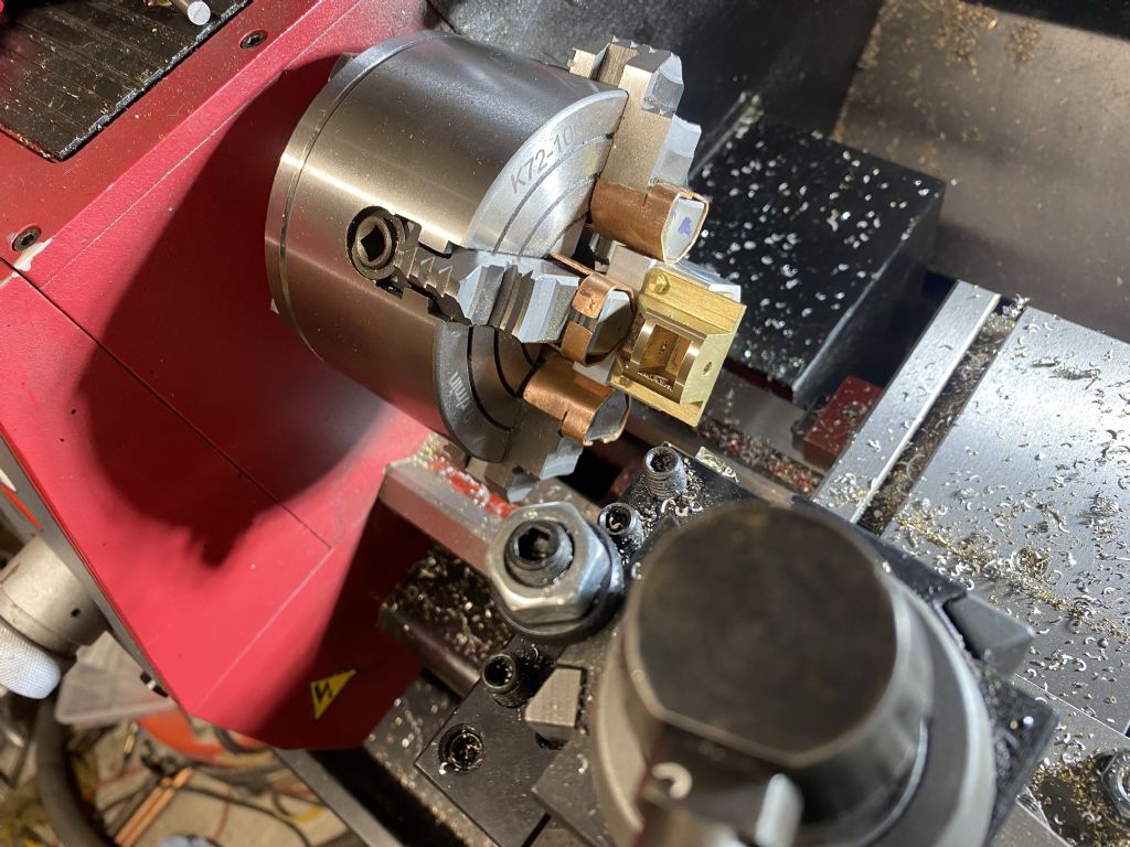
I then had to radius the rear to 3/4". I was originally going to set it up somehow on the rotary table on the mill, but as I had decided to make up a holding fixture for it, I decided to use the 4 jaw on the lathe:
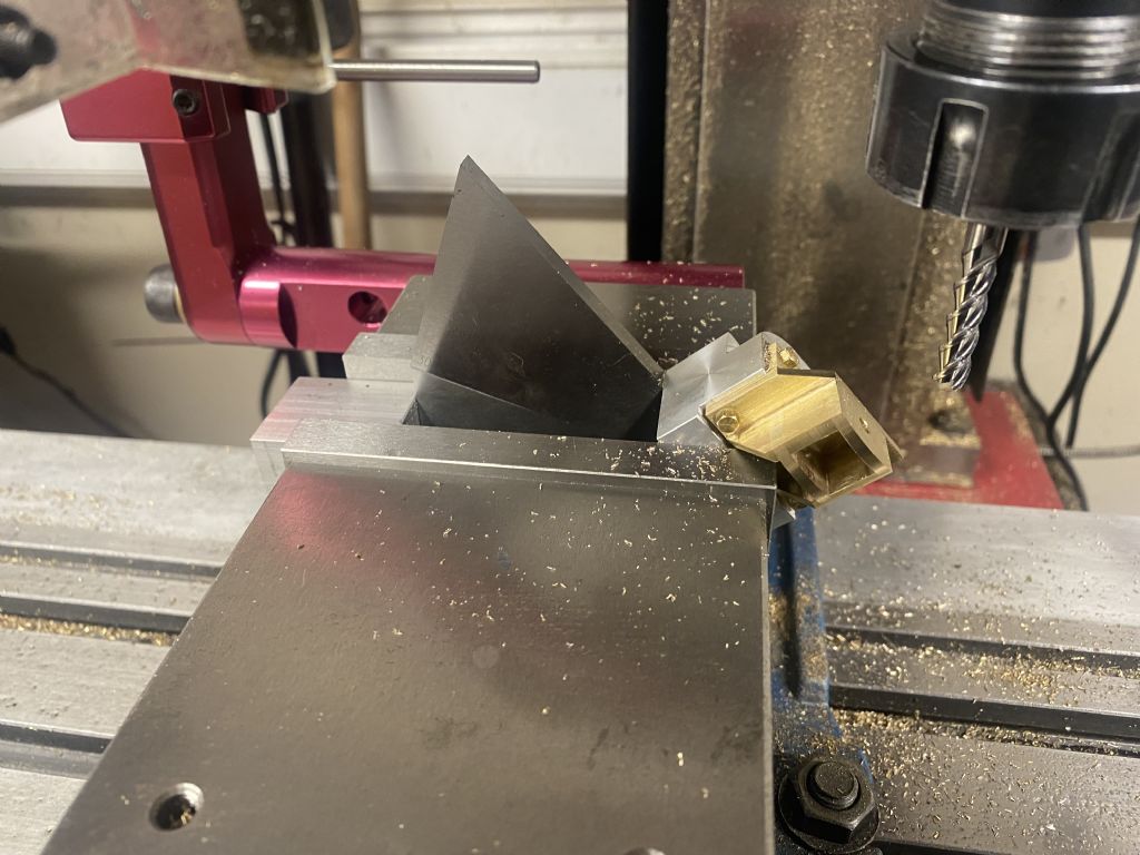
I then used the same fixture with a 50 degree angle block to mill off the bottoms:
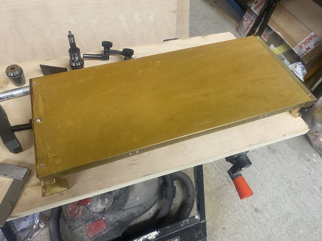
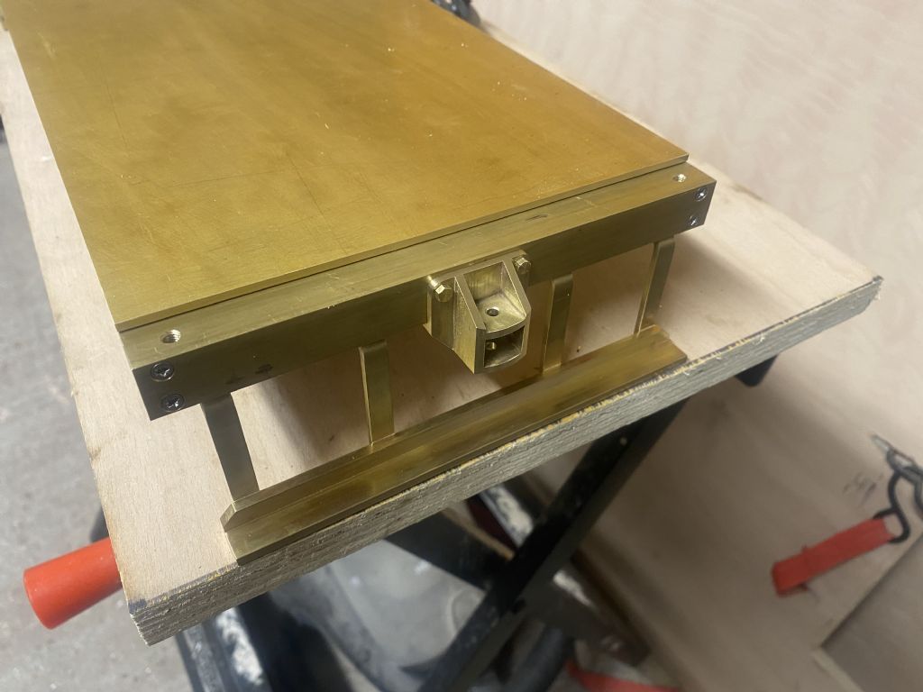
With that done, I got on with the tender tank floor, cut out of a sheet with a fret saw, then milled to dimension and test fitted:
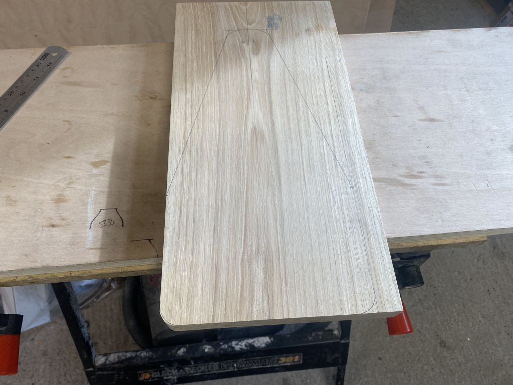
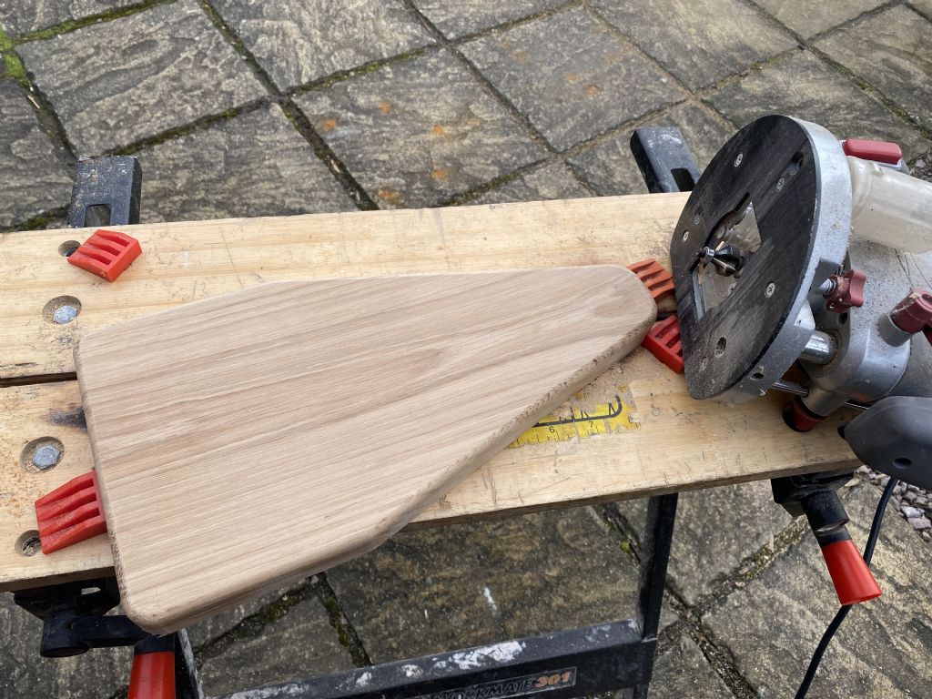
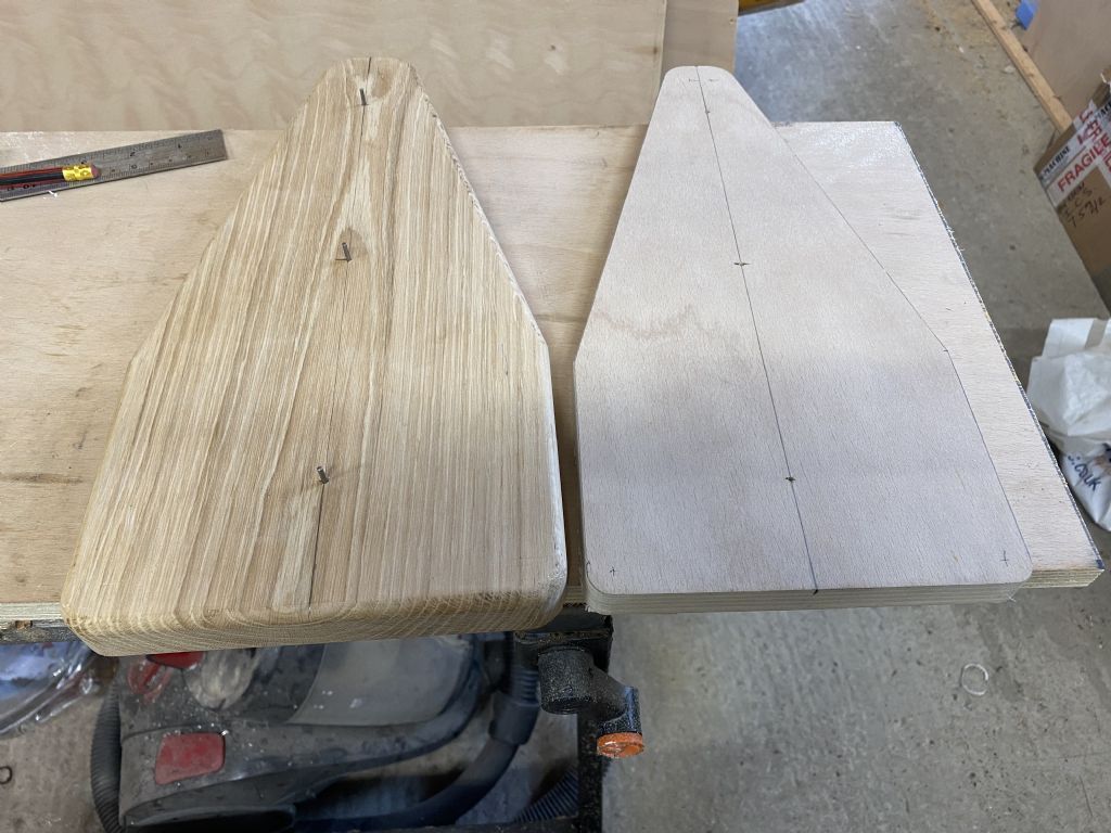
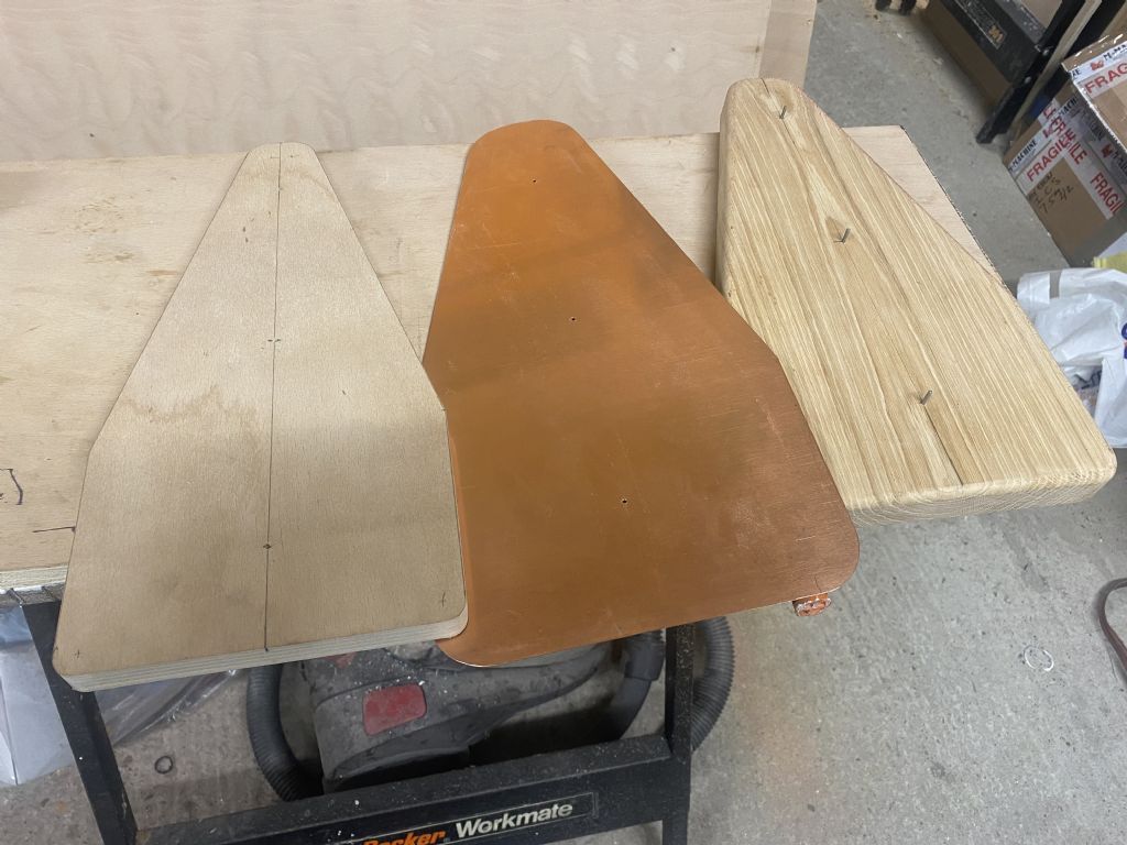
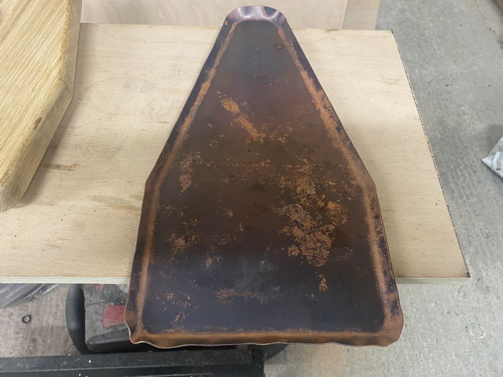
I got a bit more done this week, starting with some woodwork. I cut out the former from a block of oak that I got from e-bay a few weeks ago. I also put in 3 registration pins along the centre line, shamlessly stolen idea from Kim's build log here: Link to Kim's Build Log
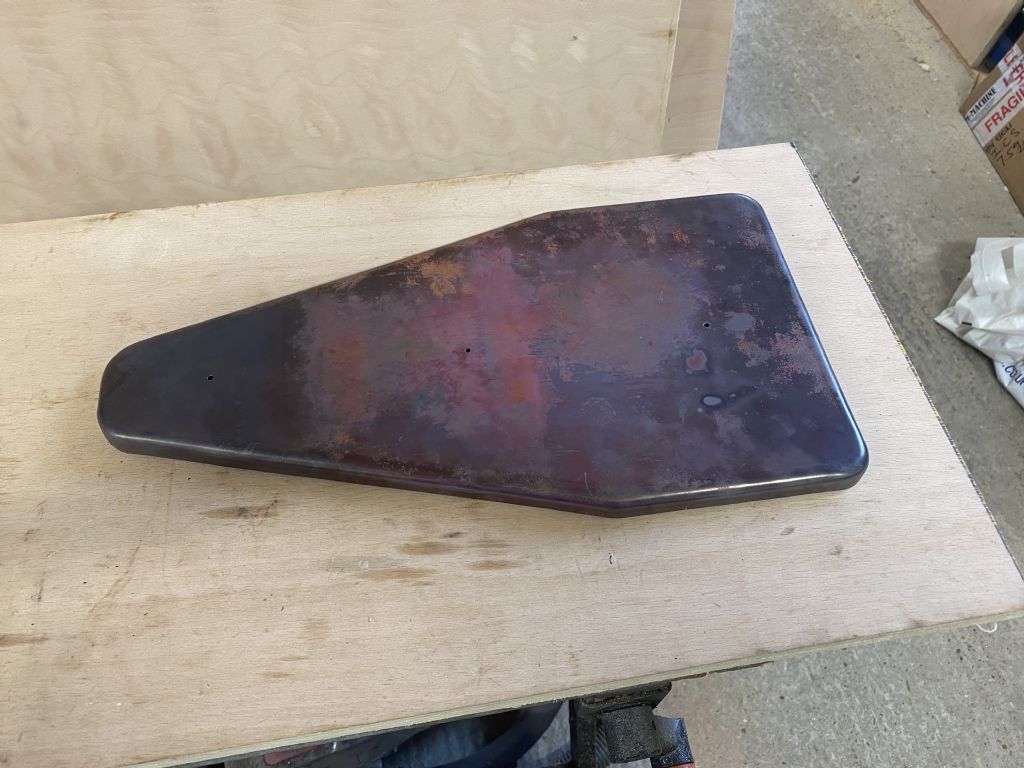
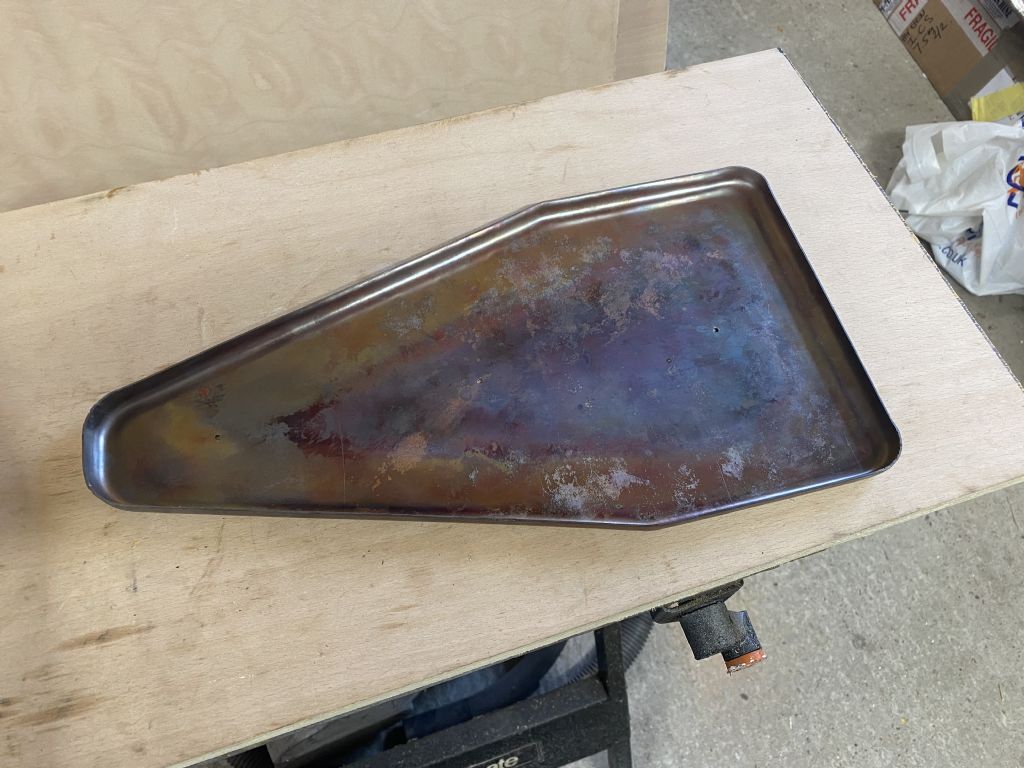
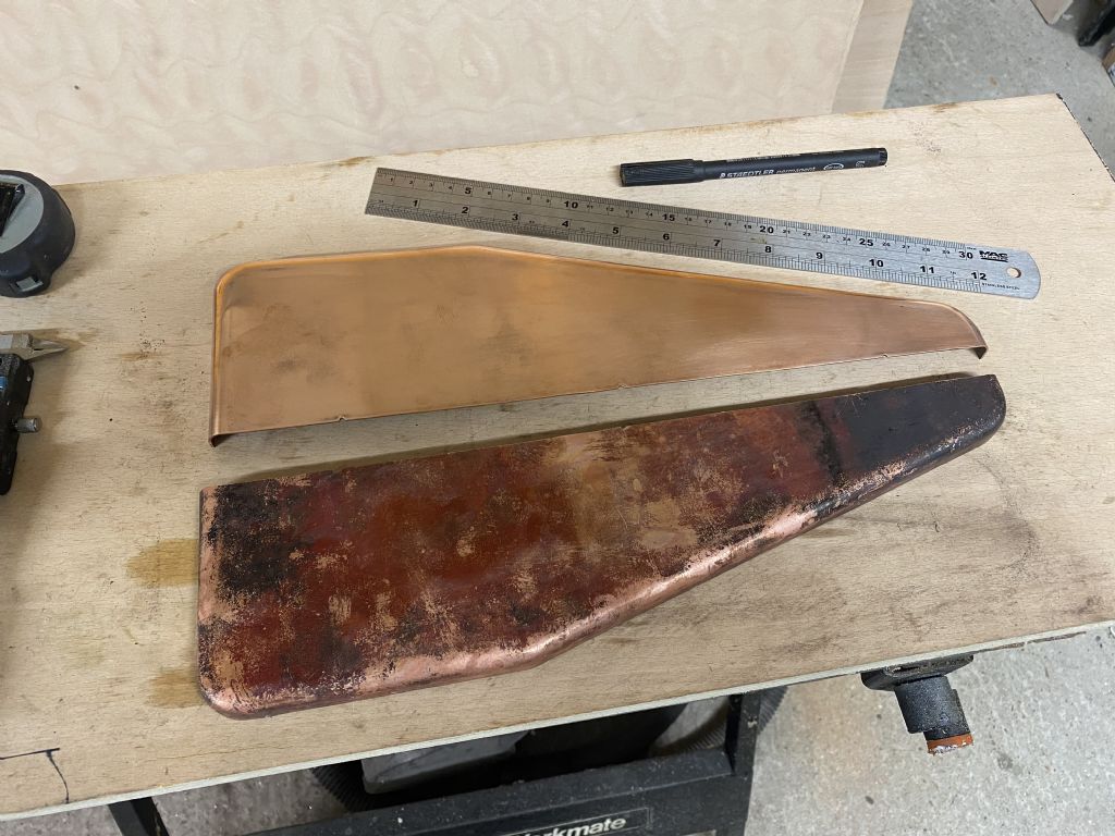
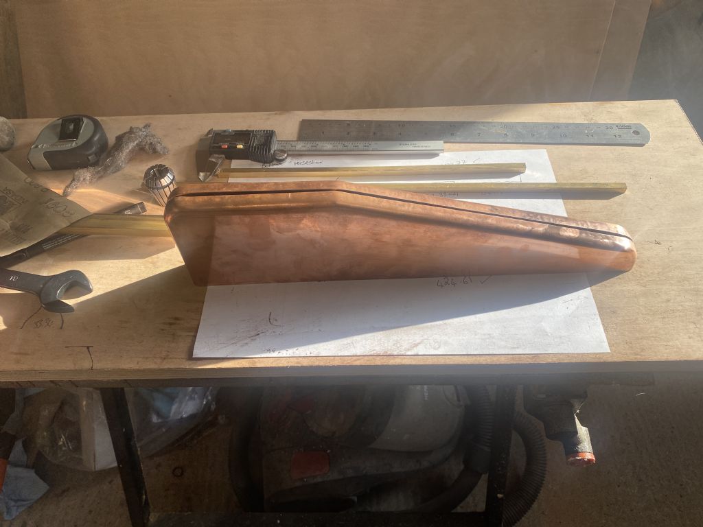
With that made up, I started rounds of annealing and hammering using my plastic faced mallet. It didn't go too badly, just one corner that I messed up a little, after a few goes with a pair of pliers and some more annealing and hammering, I managed to get it reasonable:
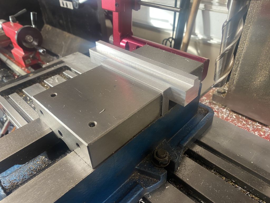
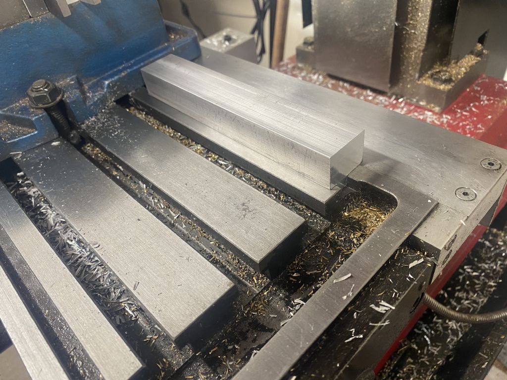
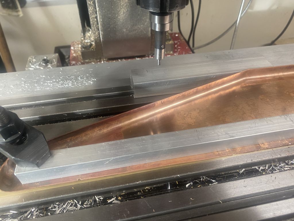
With that done, I got them separated and made up a block that fits the table on my mill to line up the top. I used the edge finder on this block to set up and square up the bottoms:
I'm now waiting for some 5/16" square brass for the bottom fixing for these, but have got a bit more done in the meantime. I'll update later
Well I started to read the other guy's blog there for a minute or two Mark – but thought I'd best stop and watch your progress here instead. ( No Spoilers then – although I have read the book! )
I like the idea of the locating pins and making the symmetrical sides in one go (instead of two pieces). I'm sure that will come in handy sometime.
My first look at this thread – making models is not my thing – but I would recommend anyone making something, to manually turn the spindle, to make something based on a wheel. No chance, if you forget to remove it, of a flailing handle which may go into orbit as it is clearly very unbalanced. On a safety scale, I’m afraid I wouldn’t rate it.
For slow turning, such as threading, a balanced manual handle could be left in situ – if one is careful.
Even more important if your lathe motor is not soft start, at the very least. Downright dangerous, potentially, IMO.
I have spent hours going through Kim’s build log, it is a great reference with loads of tips. Many thanks for your comments. There is another build website that I’m following, I’ll link to that with my next post detailing the bending Jig that I’m in the process of making.
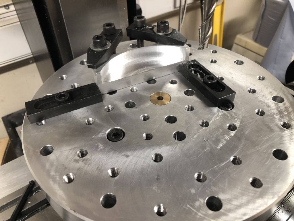
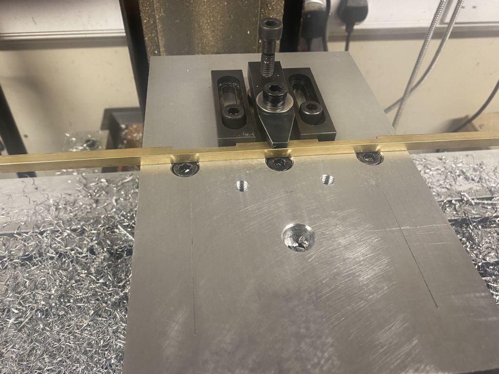
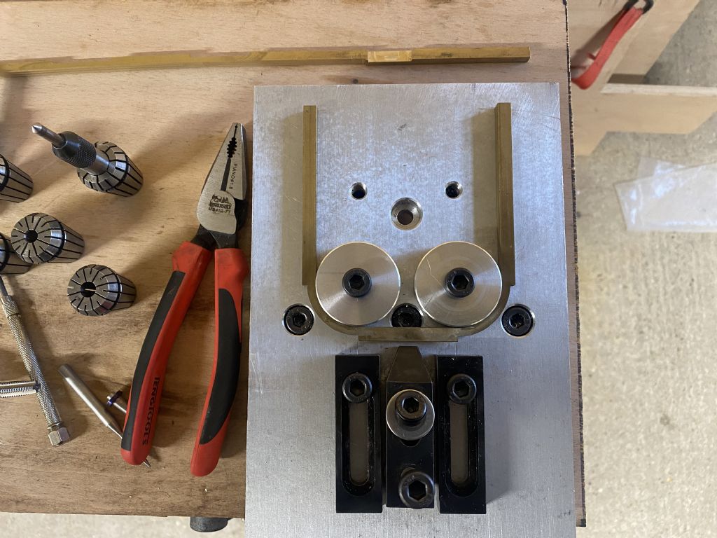
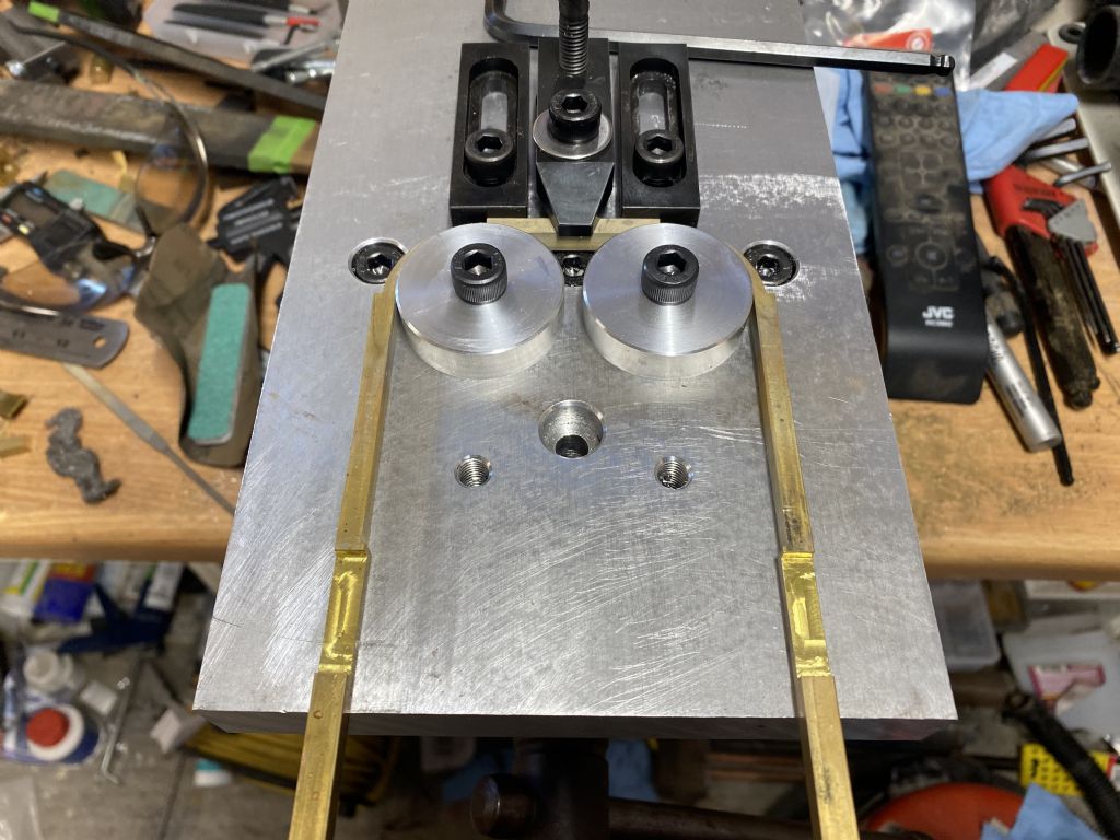
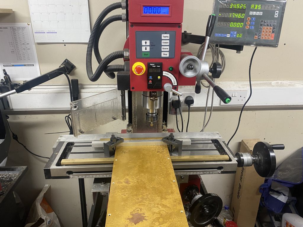
Whilst waiting for the side 5/16" square bar to turn up, I have been working away on making a 'bending jig' for the horseshoe parts. I bought the 20mm plate of ali a couple of years ago with the intention of making a mini pallet for the mill, in much the same way as the one I made for the rotary table:
I just didn't get around to it. With the horseshoe parts to bend, I have been looking around at other peoples build logs to see how they approached this. Pat Hucheson's build log gave me some inspiration and it also prompted me to start on the mini pallet. Link to Pat Hucheson's Build Log
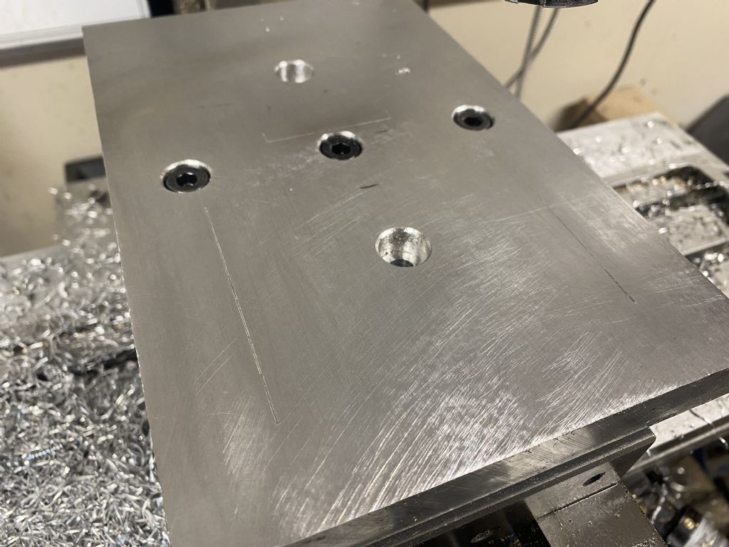
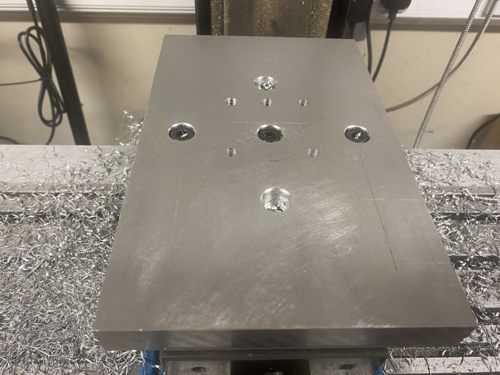
One of the annoying things with the rotary table pallet is that the holes are never in the place where I want them, so with this one, I'm just going to drill and tap the holes as I need them:
In the above photo, you can see that I have scribed some lines in the top of the pallet, I did this with a scriber tip held in a collet and used the DRO to scribe where I wanted the lines
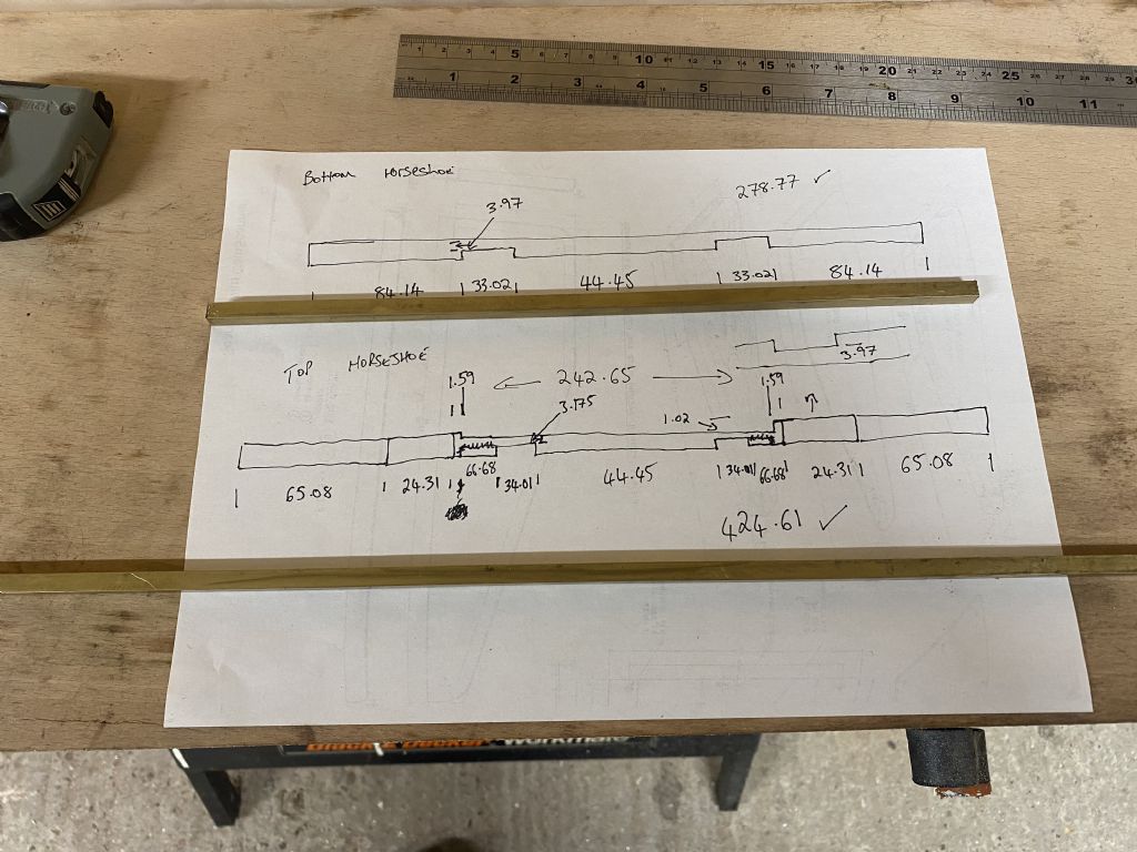
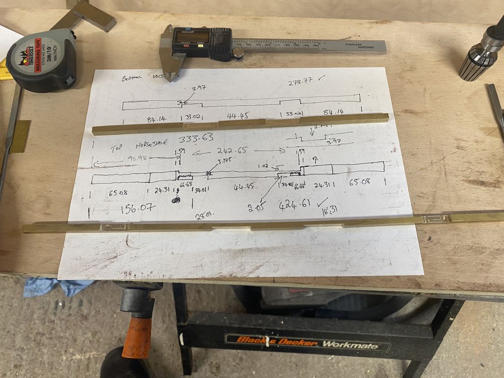
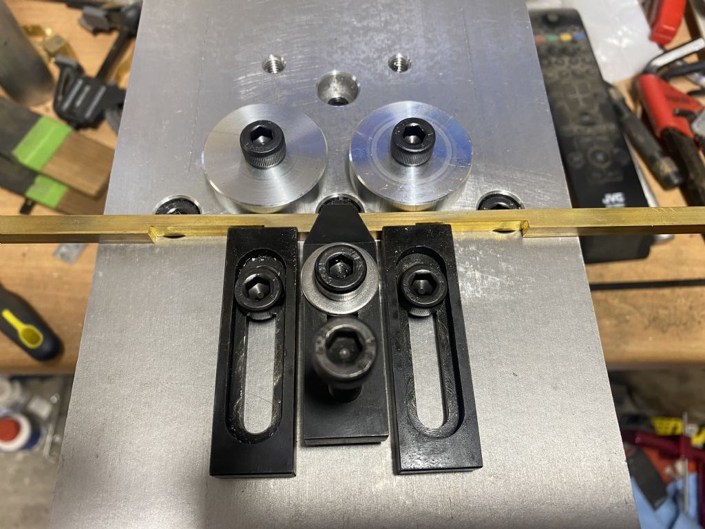
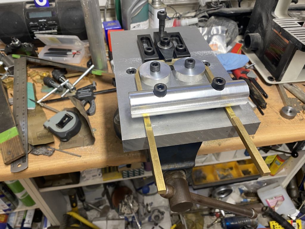
I got the bars made up and ready to bend:
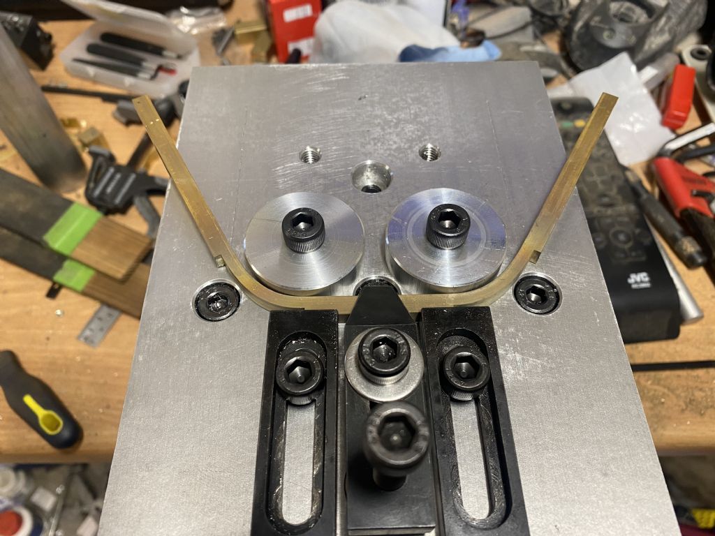
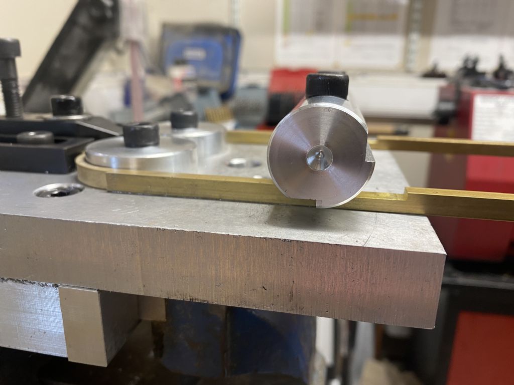
Then, with a couple of 1 1/2" dies made up, bent the first bar
Reading Kim's build log, I followed his lead and annealed these bends 4 times during the process of bending
It worked really well and apart from a couple of small tweeks, it looks like its going to do the job. The plan is to make up a set of dies for the other bar and also a couple of longer ones to bend the sheet, I'm also going to crib Pat's idea of a 11.6 degree block to bend the verge board as well.
The other thing I'm going to use the pallet for is as a holder for the die block for embossing the rivets, more on that later.
I'm afraid I can't answer that for you. As this is my first foray into engine building, I don't know how it compares. What I can say is that Kozo's instructions are excellent, with the dimensions specified being absolutely spot on so far. I'm learning a lot of new techniques and am growing in confidence with every piece that fits. I can see why the tender gets built first now.
I have got a load more done yesterday and today (helps that i'm not working at the moment, but that is going to change next week, so this build will slow down considerably)
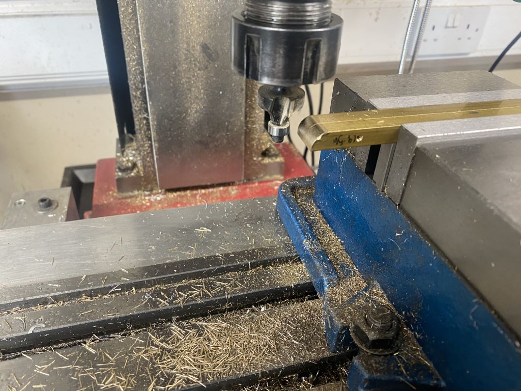
The 5/16" square for the side plate brackets turned up, so i got it to length, drilled and tapped the holes for holding it down to the bottom plate and then nicked Kim's idea of using a wood router bit to radius the ends (same router bit used for rounding the wooden former, so it should end up pretty close)
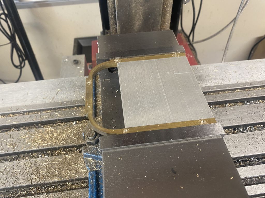
I then made up a piece of aluminium to use as a jig to hold the bottom horseshoe in the vice, then spotted and drilled and tapped the holes using the DRO to set the dimensions:
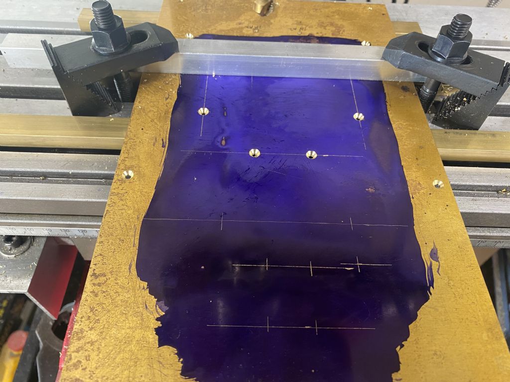
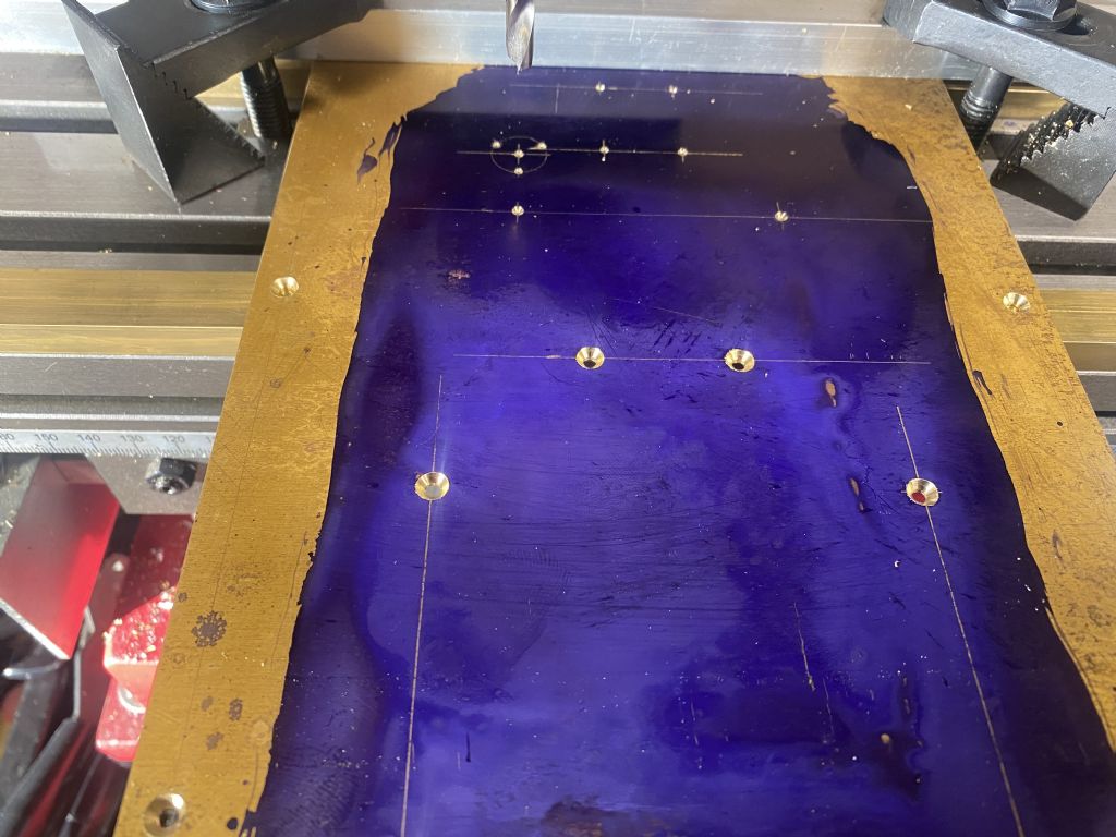
I then decided to set up and drill out the fixing holes for the side brackets and the horseshoe on the bottom plate. In the end, I decided to drill out all of the holes in the bottom plate, I was going to drill out the holes as I needed them, but its a pain to keep swapping between vice and table, so I did them all in one go. There was a bit of clamping gymnastics, but in the end, I managed to do all of the holes in 2 set ups.
I blued and scribed out the set up as a sanity check and was very pleased that all of the holes came pretty much spot on my scribe marks:
That 12.7 PCD 3 hole took me ages to get set up for on the DRO, until I realised that 0 degrees is actually on the x axis, lots of head scratching…
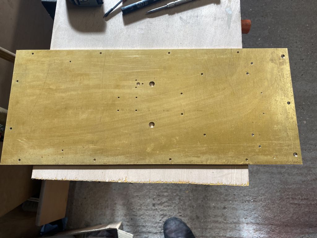
All drilled out and ready to go:
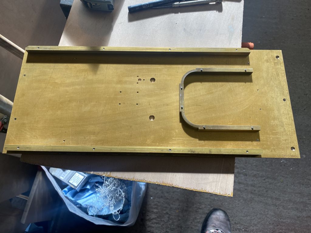
Then it was moment of truth time:
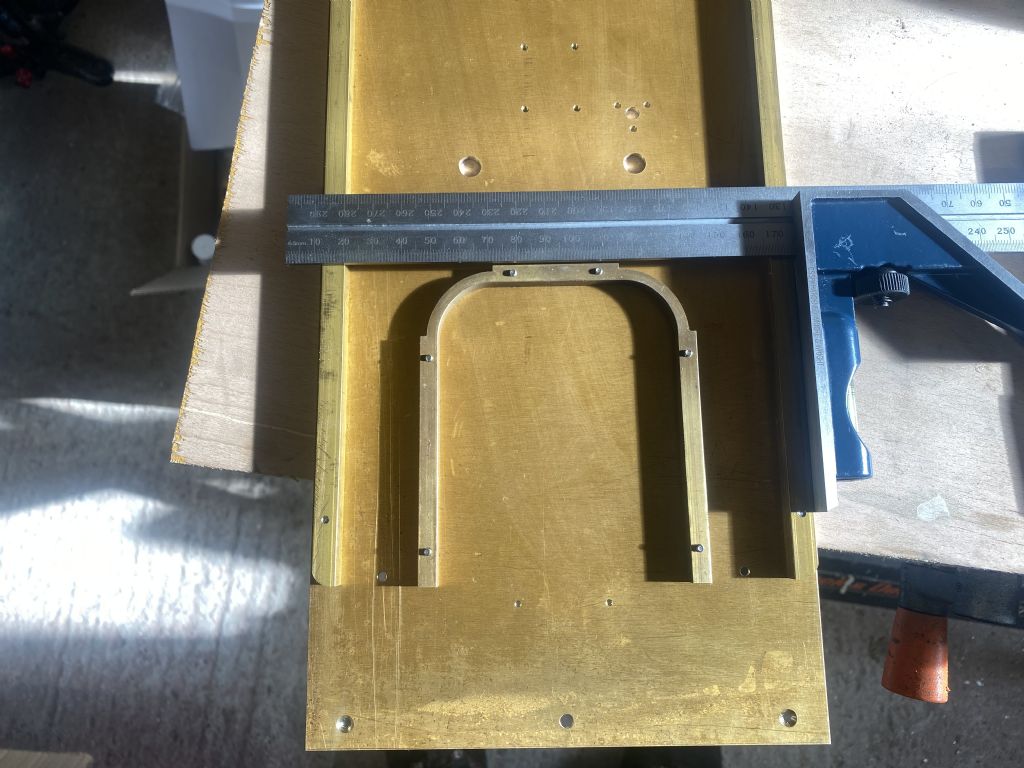
I was pretty chuffed with that, they all line up and the horseshoe is pretty square:
I made up the front little bits and the rear corner member, then had a trial fit of the sides:
Then got one side drilled, tapped and screwed together ready for soft soldering. By that time, I had had enough today.
I may have missed something Mark – but is the end-shape of the clamping bar for a particular purpose or simply the shape of the material that was to hand?
I have shaped it to accept the cut out section of the bend. If you look closely at Pat Huchison’s build photos (which is where I got this idea from) he has done the same.
I also cut that section the whole length of the clamp bar so that I can get it out once the two legs are bent up.
Sorry for the late reply here. Not much has happened since my last post. I did manage a little over Christmas last year that I didn’t document here, but I’m hoping to get back into this build soon.
I’m just starting to get back into this build, with a bit of enthusiasm. I got a bit bogged down with the sheet metalwork, so I took a break and did something I find more interesting, mechanical stuff.
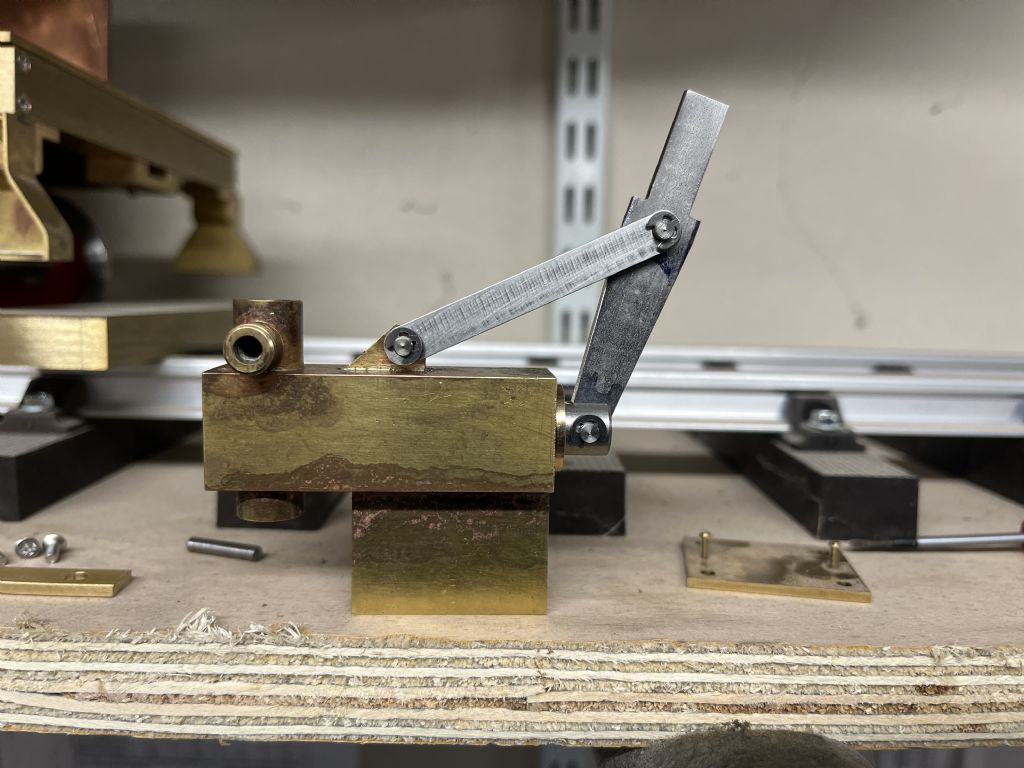
I made a start on the hand pump last Christmas, and have been making up little bits and prices for the last couple of weeks
Unfortunately, I didn’t take any photos of this progressing, but this is where I’m up to now:
I still need to Silver Solder the base on and there are a couple of holes to drill for fixings. I’m also going to re-make the plunger, I made that before I got the Stainless for the lever and I cut the slot at 3.175 (1/8&rdquo when I got the metal for the lever, I couldn’t find any 1/8” so ended up with 3mm that is actually 2.9. Upshot is, the slot is too wide.
I’m going to make an effort to keep this build log updated going forward.
Yes, that is an option, but i'm probably going to re-make the piston. As you will see with this update, re-making parts is not unusual for me…
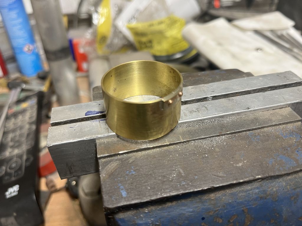
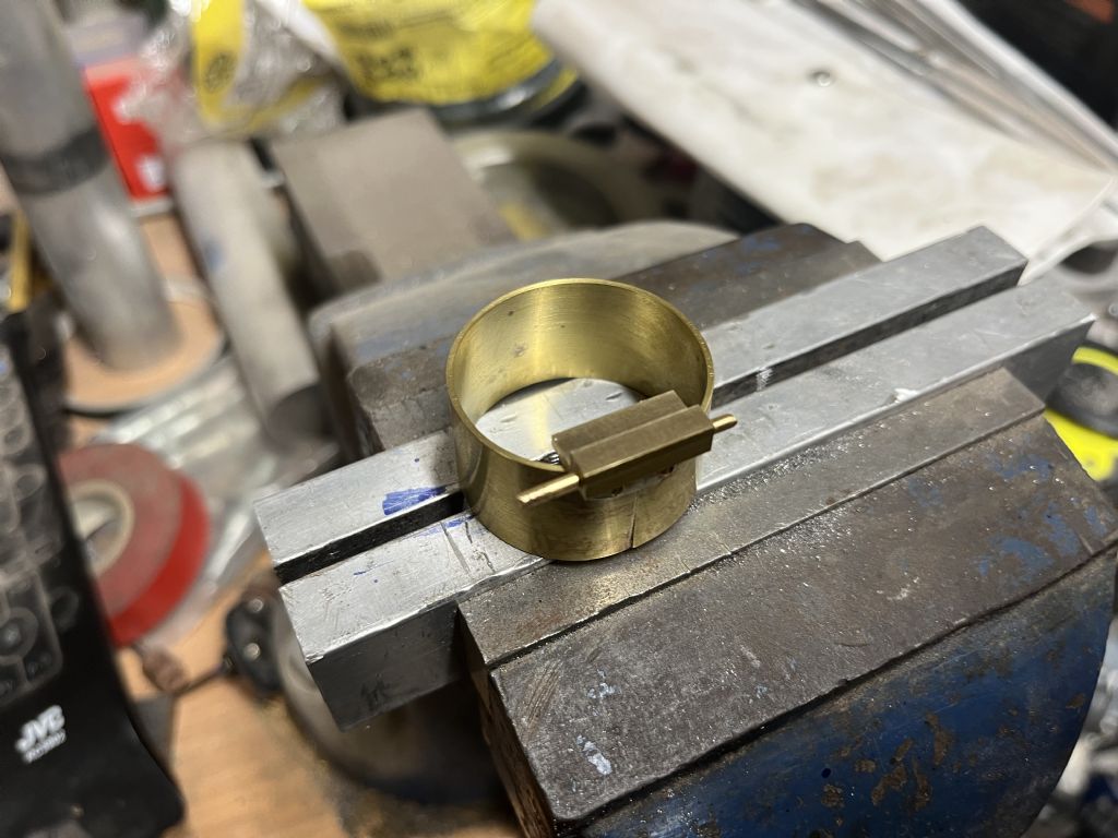
Todays update is really a few weeks work starting with the manhole:
I got the brass rolled and the little joiner piece silver soldered on, but missed the fact that the joiner piece wasn't quite square, it came back to bite me later. I also made a start on the hinge pieces
And this is where the non square joiner piece started to give me grief:
I wasn't happy with that, so started re-making this part, only this time, taking a lot more care to get things square and equal.
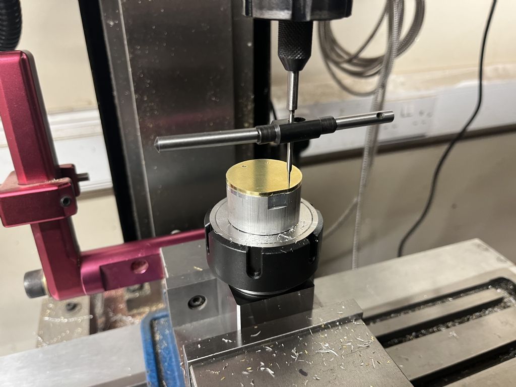
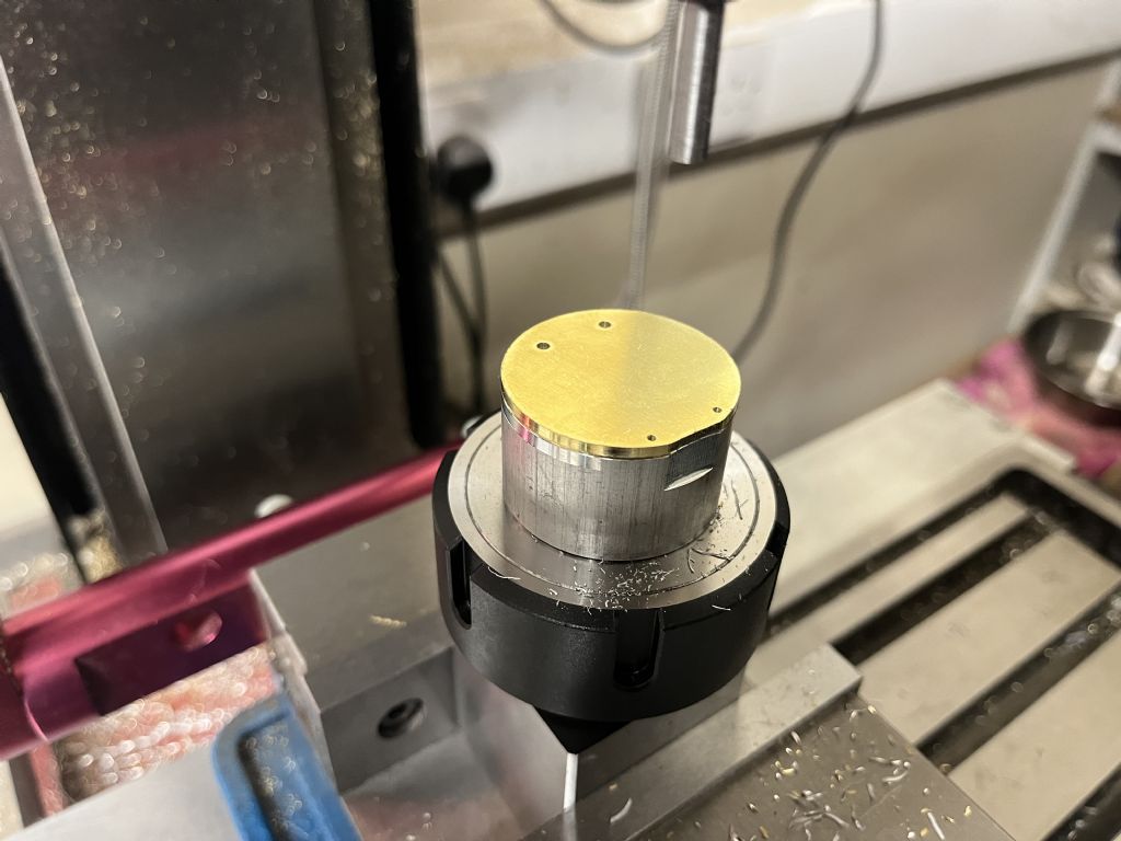
I also made up a superglue arbor and turned down the manhole lid, then transferred it to the mill, to square off the edge and drill and tap the hinge holes and drill for the handle:
I have the new manhole tube silver soldered up and the joiner piece is now square, (no photos) just need to sort out the piece at an angle and get it silver soldered up and turned down, i'm hoping this one comes out a bit better than the first effort.
Thanks for the heads up. I’m a big fan of Blondiehacks and it is good to see that she is starting on the bit that I’m least looking forward to – the boiler. It will be good to see how she gets on with it, I’m sure there will be some good tips for when I get around to this bit.
I’m looking forward to getting this tender finished and moving on to the mainframes of the engine. I have ordered the castings for the wheels and the cylinders from Friends Models in the US, I’m hoping they will be with me at some point in the near future.
I keep doing stuff, with not much to show.
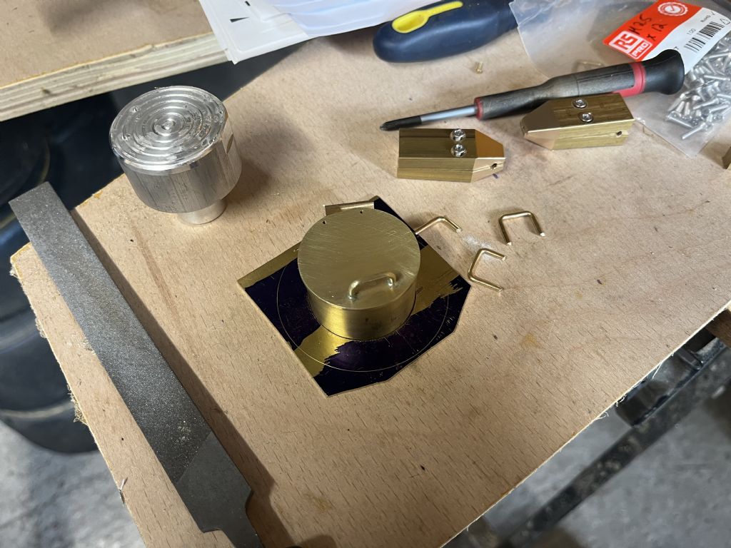
I got the handle for the manhole lid bent up and silver soldered into place:
You can see all of the rejects in that photo. I ended up making a variation on Kozo’s bending tool, that is also in the photo above.
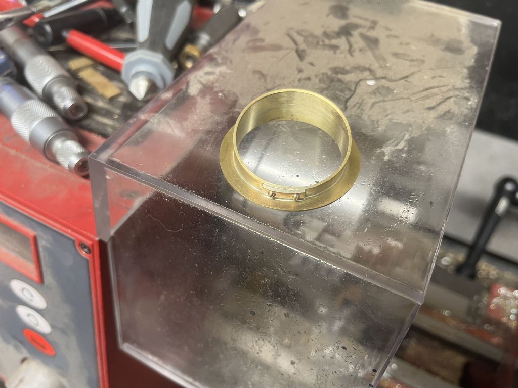
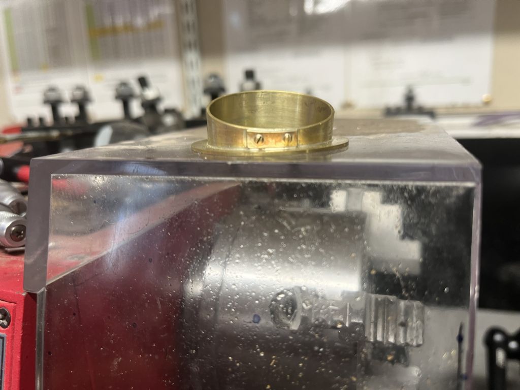
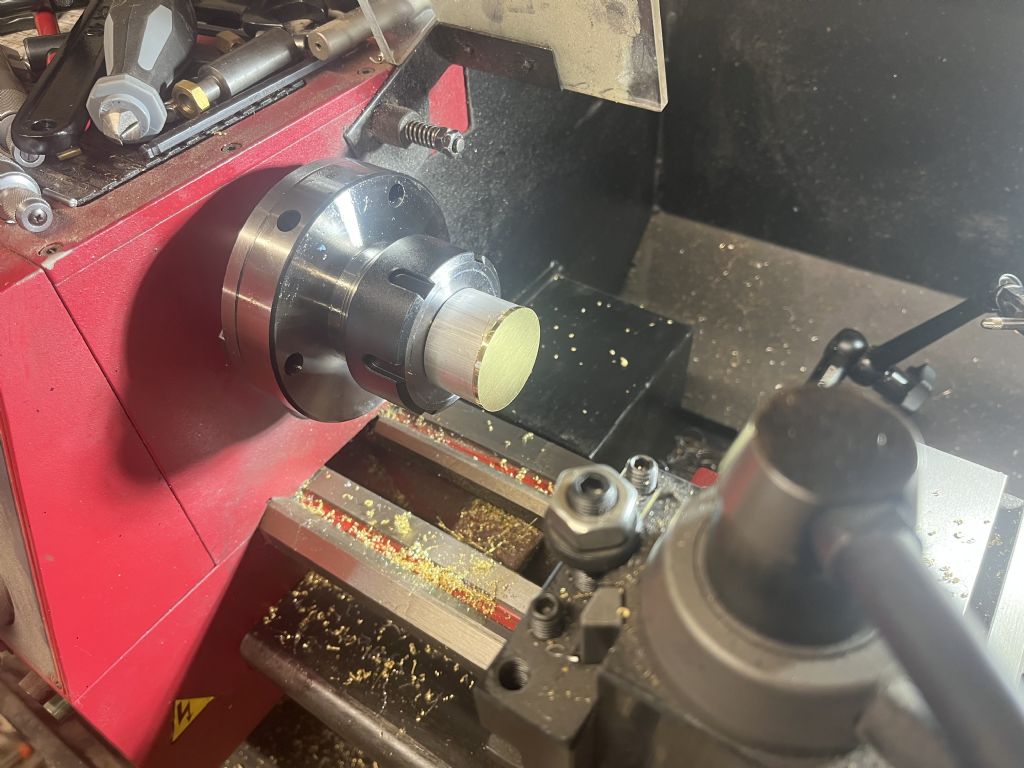
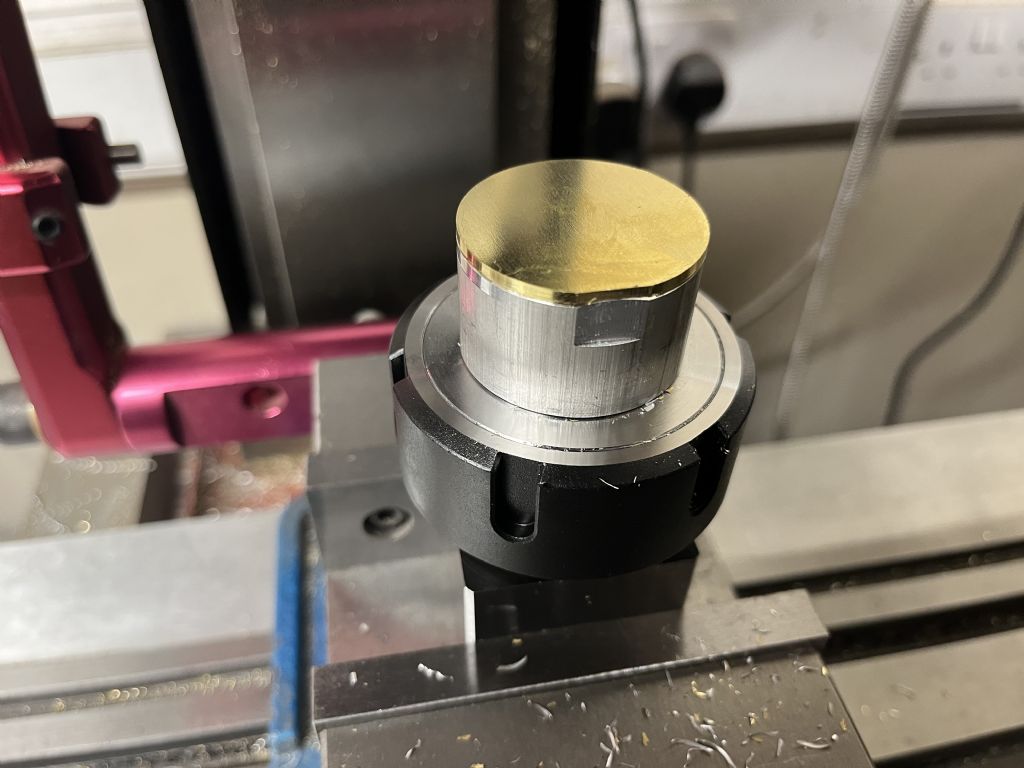
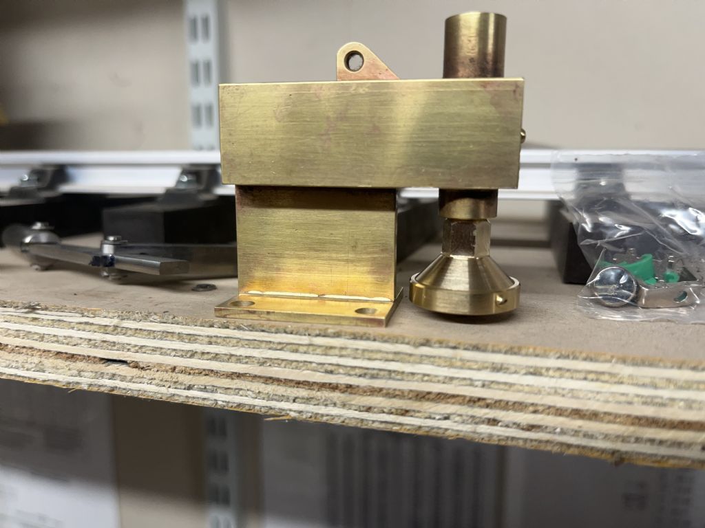
I have also got the suction funnel made and followed Kim’s lead and made a removable ring to hold the brass screen in place
I keep putting off the verge board with the little edge that needs silver soldering on, and all of the sheet metal and false rivets. I’m going to have to bite the bullet soon with those though.