Thanks John – that is a good start!
I don't have a picpet – I do have a lot of other circuitry around the pendulum , some not quite working yet, nor relevant to the basic principles I still hope to discover. There is a differential, rotary vane variable capacitor , a sort of rotary encoder, that attaches to the pivot – this method because only the vane attaches to the pivot point – so there is no added friction from encoder bearings, etc – I hope to achieve 0.1deg resolution from this device over 4deg angle. A variation of the concept in this pdf:
Seismometer
This to get a sinusoid per cycle and hope to integrate to rate to get energy loss/cycle – but that is for MUCH later.
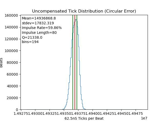
I also have a time-to-digital converter ( Texas TDC7200) that gives delta between two edges, down to 10 or so ns resolution. I intend to feed the start pulse from the 1Hz output of my GPSDO (note, NOT GPS 1PPS, but the 1Hz divided down from the 10MHz disciplined osc) , which is quite good quality, and the stop pulse from the opto on the pendulum. A log of that variation of delta data should give the decay rate?
That is my version of the picPET…
The accelerometer is complex- basic mems devices won't work – DC accelerometers measure gravity and that swamps the small accelerations in a pendulum. Also, the sensitivity of these devices seems to be around +-0.5G, with 0.02mg/bit – still not good enough, even in Tilt measurement mode using two axes. 'True' vibration type sensors, piezo with charge amps are the better option, with bandwidth reduced to 5Hz or so, but the devices are two big to fit in the pendulum and there is a non-piezo coax cable to contend with, and a large price! I have fitted the 0.5G device – it gives usable data, but not good enough for deep analysis..
The Pendulum pivot is knife edge type.
If this thing gets of the ground and is even half as good as the rest of the pendulums on the forum, I will post photo's etc – else I will just go quiet..
Thanks John
edit:
This is not clear to me-
The amplitude is estimated for each pendulum cycle by an opto and a picPET, deriving the amplitude from the pulse length.
What is the pulse length? Is it the length of the pulse out of the opto-interrupter? ie, low when the vane blocks the aperture, and high when it opens again, so the time between the hi-to-lo and lo-to-hi edges ( ie, the width of the light-blocking vane), or the time between two rising (for example) edges. If the latter, is that edge always in the one direction of swing, ie, the edge when the vane passes from left to right through the aperture, or both, ie, from left to right and then back from right to left
I have difficulty making myself clear here-
Edited By Joseph Noci 1 on 10/08/2023 13:58:25
 Michael Gilligan.


