PCB CNC

Advert

PCB CNC

Viewing 3 posts - 26 through 28 (of 28 total)
  • Author
    Posts
  • #331457
    Another JohnS
    Participant
      @anotherjohns

      Also, if you use LinuxCNC, (and probably PathPilot) it can directly read an image file (jpg is what I use) and it will allow you to engrave from that.

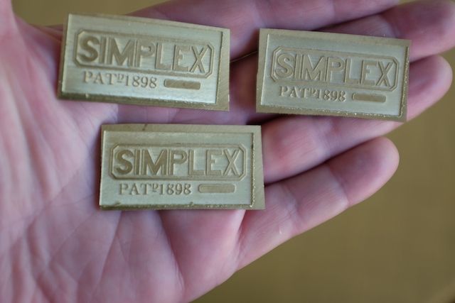
      I did write an article a while ago, (which is sitting in our worthy Editor's future-list – or did it get printed?? can't remember) for making some name plates from a wonky photograph – first part was straightening the photo, then sharpening the letters, the second part was the engraving part.

      It was done for a friend who is making a Canadian 0-6-0 switcher, and the tender truck bolsters had the maker's name on the ends in raised letters. He's very happy with the results, and the cost was only in the materials and engraving cutters.

      We'll see if the article makes it to print, or if it is too detailed/specific for Model Engineer.

      The resulting blanks (requiring fettling and trimming by my friend once attached to the bolsters) should be shown below.

      Fun Stuff!

      JohnS.


      simplex truck parts

      Edited By John Alexander Stewart on 10/12/2017 16:58:10

      Advert
      #331459
      Paul White 3
      Participant
        @paulwhite3

        John, thanks for the above info. At the present I just want a package to print labels as I do not have engraving facilities Joe kindly offered me a label making method,

        Thanks for the response

        paul.

        #332312
        Brian Corrie
        Participant
          @briancorrie54124

          Posted by Joseph Noci 1 on 09/12/2017 20:13:16:

          Hi Brian,

          The floating spindle is fairly simple – the spindle ( itself just an RC brushless motor the main shaft of which removed and fitted with an 8mm long body ER8 collet chuck) – sits on the horizontal cross member in the photo below. That member has two 10mm vertical shafts that slide in the two aluminium blocks ( left and right) which are fixed to the Z axis. The nose of the spindle has a fine thread screw-in cone, fitted with a PTFE 'shoe' that rides on the PCB, with the engraving tool set to protrude below the shoe by the depth of the copper on the PCB – about 40um or so.

          Some pics that may assist:

          Spindle bussines end-

          The floating 'foot'

          The 'grooves' in the PTFE foot are so air can be sucked in via the vacuum attachment – see later pic down the line.

          Floating Head in down position

          And here in 'raised, position – as it would be when the foot touches the pcb and lifts the head.

          The black elbow pipe in the pic above is a Vacuum attachment point – sucks up the debris through the nose cone and foot, keeping the PCB clean and clear of shavings – else the foot rides high and the engraving tip does not penetrate properly.

          These tracks have a 0.12mm isolation cut ( the light shining through the groove) and the pads in the center for the IC are 0.5mm wide.

          Hope that helps – ask if your want more detail. Important that the slide that the spindle rides up and down on on the Z axis ( not the z Driven axis..) is a close fit – no slop, since this will translate to poor track definition and resolution.

          regards

          Joe

          Thank you very much for the detailed explanation Joe, it was very clear and has inspired a cunning plan.

          Best regards, Brian

        Viewing 3 posts - 26 through 28 (of 28 total)
        • Please log in to reply to this topic. Registering is free and easy using the links on the menu at the top of this page.

        Advert

        Latest Replies

        Viewing 25 topics - 1 through 25 (of 25 total)
        Viewing 25 topics - 1 through 25 (of 25 total)

        View full reply list.

        Advert

        Newsletter Sign-up