PCB CNC

Advert

PCB CNC

Viewing 25 posts - 1 through 25 (of 28 total)
  • Author
    Posts
  • #310075
    Colin Osborne
    Participant
      @colinosborne20186

      Hi all,

      I'm guessing this is the right place for this topic. As a Radio Amateur I get the relevant publications and in one of the recent ones, Practical Wireless, there was an article for using a CNC router to cut PCB's. The author did not give the make of the one he bought and assembled, but it looked to be quite a useful piece of kit. But, although I build, repair and generally swear at computers, I am in the dark on this black art.

      Has anyone used one of these types? Obviously they are small but that suits me just fine as my tiny workshop already has a lathe, a bench pillar drill and a large grinder. So if I decided to buy one of these routers it would go in my 'play room' upstairs. Apart from the PCB side of things what are the other uses I could put it to? In other words, what would be its limitations? I'm not after making a full sized model of 'The Flying Scotsman', I can do that later with a hacksaw and a filelaugh.

      I have had a quick look on the web and can see, like all things, there are varying prices and you only get what you pay for, but if anyone has got one, or used one, and can give an opinion on them I would be most grateful.

      Cheers, Colin.

      Advert
      #15158
      Colin Osborne
      Participant
        @colinosborne20186

        In the dark!

        #310079
        Neil Wyatt
        Moderator
          @neilwyatt

          Strikes me that if you had a 3D printer, you could print a dremel holder to replace the print head.

          If you can level a 3D printer properly, then it's level enough to engrave PCBs.

          Neil

          #310085
          Joseph Noci 1
          Participant
            @josephnoci1

            Hi Colin,

            I built my own 'mini-router' specifically for isolation engraving of PCB's. The kind of PCB's you want to do will determine the characteristics of the machine.

            For very fine tracks ( I do down to 0.4mm tracks with 0.4mm spacing between tracks..):

            The machine should be as rigid as possible with 'no' backlash in the leadscrews.

            The spindle should be as high speed as possible ( 20000RPM is good, 30000RPM is great), The cuuter tip is very fine – maybe around 0.15 to 0.2mm at the cutting edge, and speed is needed.

            The cutter geometry is critical – D-type engraving tips made from fine-grain carbide are needed, esp if working with FR4 – a fiber-glass PCB substrate. Cutter penetration is a scant 20um to 35um, so only the very tips does the work, and if that tip grind , relief, etc, is incorrect, all you get are ragged burrs and poor engraving!

            And last, but very necessary, a floating spindle makes for a good engraving! Since the engraving tip is conical, the deeper you go, the wider the groove, and the more you cut away of the copper track sides. So maintaining depth is critical. Trying to get the router table perfectly flat is not easy – the frame of the router is flexible enough that if the machine is on a table top, just the flex in the table top makes for many 10's of um twist in the router table, which mucks with your depth. And then the PCB material is not perfectly uniform in thickness either, and it is almost impossible to keep the PCB flat on the router table either – some folk superglue it down, etc, but flat is never is. So, use a floating spindle , running on a teflon foot on the pcb, and depth is fully controlled.

            If you get a handle on these elements, then the process works, is totally repeatable, and makes great PCB's – I have made hundreds this way!

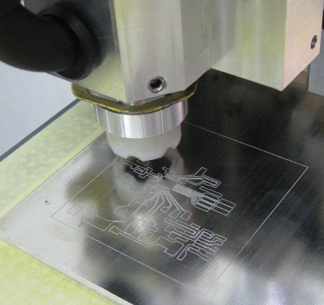
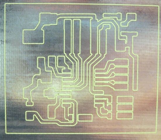
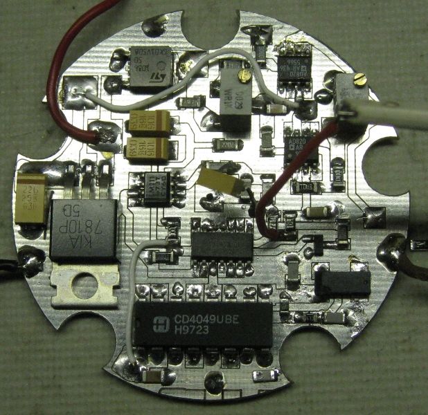
            Here are some pics of my engraver and an example PCB for a very fine pitch surface mount IC..

            The machine table is about 400mm long by 300mm wide – small but very rigid.
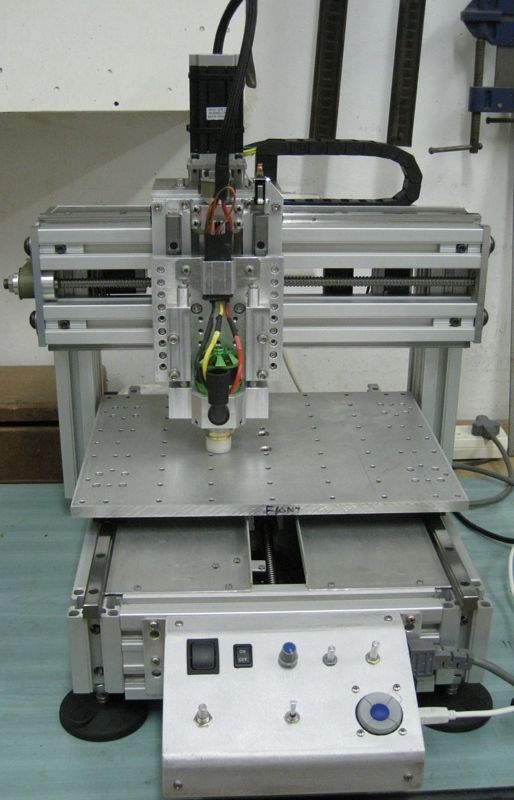
            Mini-Router/Engraver

            CNC Engraver Floating Head

            PCB Being Engraved

            I use the same engraver to pick and place the IC on the engraved PCB using a vacuum plunger..

            The tracks and pads on this IC are 0.5mm apart..

            Small IC placed on engraved PCB

            I sharpen my own engraving tips on a diamond wheel on the small T&C grinder I made.

            engraver tip sharpening1.jpg

            Regards

            Joe

            #310097
            John Stevenson 1
            Participant
              @johnstevenson1

              Have a look up at the one sold by Banggood and demonstrated by Myford Boy. On you tube
              Not as class as Joseph’s but quicker to obtain and a damn sight cheaper

              #310109
              Colin Osborne
              Participant
                @colinosborne20186

                No 3D printer yet, Neil, but it's on my list!

                Wow! Joseph, that is some router, well done. I don't think that I need to go that far though, I don't do that many PCB's but I did used to etch them using Ferric Chloride, that is messy and it stains! Although the results are good. I have been using a Dremel type drill with a dentists bit. It works but is not ideal!

                This is why I wondered what else it would be useful for, so I could justify getting one. I have to admit, to me it is one of those pieces of equipment that I would love to have so will find an excuse to use it!…… Aw, c'mon, I can't be the only one who thinks like that! ….. Am I? (the same goes for the 3D printer, Neil!)

                John, thanks for that, I'll take a look. Much appreciated!

                Cheers, Colin.

                #310121
                Douglas Johnston
                Participant
                  @douglasjohnston98463

                  That is a super machine you have there Joseph. Did you use ball screws for the X-Y-Z motions? I was also intrigued with the use of the model helicopter type motor for the spindle, was that easy to power?

                  Doug

                  #310129
                  Anonymous
                    Posted by Douglas Johnston on 03/08/2017 09:39:43:

                    That is a super machine you have there Joseph.

                    Indeed it is, very professional, I'm impressed.

                    But (there's always a but) I suspect the usefulness depends on circumstances. I'd make a guess that PCB manufacturers are not ten a penny in Namibia? So for Joseph it is essential. However, in the UK there are several companies that will take CAD data and manufacture small quantities of simple double-sided and multi-layer PCBs at reasonable prices. Certainly much cheaper than a PCB router. We had a PCB router at the last company I worked for, very expensive as I recall, but simply didn't get used. It couldn't cope with the standard track and gap widths used and was too slow.

                    Ah, I remember 'drawing' tracks on PCBs and using ferric chloride as a kid, but almost no surface mount in those days! Got banned in the end as I left too many stains around the house, and ruined too many clothes. Generally I no longer do electronics as a hobby, but if I was I'd get PCBs made outside. That's what I'll be doing when I get around to completing the design for my traction engines lamps, using LEDs but driven to simulate the instability of a naked flame.

                    Andrew

                    #310161
                    Colin Osborne
                    Participant
                      @colinosborne20186

                      Andrew, I'm glad that I am not the only one to be leaving those stains around the house! As you so rightly point out, these machines are expensive for what their output is, certainly in my case. I think I will stick to using the dremel like tool I have and put the money towards a 3D machine. Maybe that suggestion of Neil's could be investigated! Come on Neil, it was your suggestion, how would you go about it? A nice MEW article project for you!

                      There was one thing I did find out from looking at web pages, and that was how the cutters used to make the 'tracks' were shaped. I have been using some dentists drills I managed to scrounge years ago, freehand, it doesn't take much to make a mistake! If I can get hold of some cutters that will fit into the 'dremel' and make a stand with a scissor like action on a swivel arm that would keep the 'dremel' upright and firm it could be all I need. Or at least better than what I am doing at the moment. I'll have a think…….zzzzzzz!

                      Cheers, Colin.

                      #310166
                      Brian G
                      Participant
                        @briang
                        This looks like a useful alternative to engraving the PCB by hand.
                        Brian
                        #310186
                        Colin Osborne
                        Participant
                          @colinosborne20186

                          Ha! That is basically what I had in mind, apart from the bit that does the tracing. Just guiding the cutter by hand. Not sure about the 'painting' though!

                          If I do have a go at it, I think I would rather make the pantograph from Alumimiun than from wood.

                          Many thanks, Brian! At least I now know it wasn't such a scatterbrained idea after all. And that there is nothing new in this world!!

                          Cheers, Colin.

                          #331288
                          Brian Corrie
                          Participant
                            @briancorrie54124

                            Posted by Joseph Noci 1 on 02/08/2017 22:59:22:

                            Hi Colin,

                            I built my own 'mini-router' specifically for isolation engraving of PCB's. The kind of PCB's you want to do will determine the characteristics of the machine.

                            For very fine tracks ( I do down to 0.4mm tracks with 0.4mm spacing between tracks..):

                            The machine should be as rigid as possible with 'no' backlash in the leadscrews.

                            The spindle should be as high speed as possible ( 20000RPM is good, 30000RPM is great), The cuuter tip is very fine – maybe around 0.15 to 0.2mm at the cutting edge, and speed is needed.

                            The cutter geometry is critical – D-type engraving tips made from fine-grain carbide are needed, esp if working with FR4 – a fiber-glass PCB substrate. Cutter penetration is a scant 20um to 35um, so only the very tips does the work, and if that tip grind , relief, etc, is incorrect, all you get are ragged burrs and poor engraving!

                            And last, but very necessary, a floating spindle makes for a good engraving! Since the engraving tip is conical, the deeper you go, the wider the groove, and the more you cut away of the copper track sides. So maintaining depth is critical. Trying to get the router table perfectly flat is not easy – the frame of the router is flexible enough that if the machine is on a table top, just the flex in the table top makes for many 10's of um twist in the router table, which mucks with your depth. And then the PCB material is not perfectly uniform in thickness either, and it is almost impossible to keep the PCB flat on the router table either – some folk superglue it down, etc, but flat is never is. So, use a floating spindle , running on a teflon foot on the pcb, and depth is fully controlled.

                            If you get a handle on these elements, then the process works, is totally repeatable, and makes great PCB's – I have made hundreds this way!

                            Here are some pics of my engraver and an example PCB for a very fine pitch surface mount IC..

                            The machine table is about 400mm long by 300mm wide – small but very rigid.
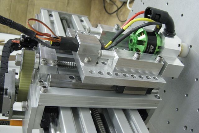
                            Mini-Router/Engraver

                            CNC Engraver Floating Head

                            PCB Being Engraved

                            I use the same engraver to pick and place the IC on the engraved PCB using a vacuum plunger..

                            The tracks and pads on this IC are 0.5mm apart..

                            Small IC placed on engraved PCB

                            I sharpen my own engraving tips on a diamond wheel on the small T&C grinder I made.

                            engraver tip sharpening1.jpg

                            Regards

                            Joe

                            Hi Joe, could you give some more details of your floating spindle design? I have a Chinese CNC which is sort of OK for pcbs but this looks like it would be a good retrofit

                            Cheers

                            Brian

                            #331298
                            Joseph Noci 1
                            Participant
                              @josephnoci1

                              Hi Brian,

                              The floating spindle is fairly simple – the spindle ( itself just an RC brushless motor the main shaft of which removed and fitted with an 8mm long body ER8 collet chuck) – sits on the horizontal cross member in the photo below. That member has two 10mm vertical shafts that slide in the two aluminium blocks ( left and right) which are fixed to the Z axis. The nose of the spindle has a fine thread screw-in cone, fitted with a PTFE 'shoe' that rides on the PCB, with the engraving tool set to protrude below the shoe by the depth of the copper on the PCB – about 40um or so.

                              Some pics that may assist:

                              Spindle bussines end-

                              spindle2.jpg

                              The floating 'foot'

                              The 'grooves' in the PTFE foot are so air can be sucked in via the vacuum attachment – see later pic down the line.

                              nose bits1.jpg

                              nose and tool1.jpg

                              fitting nose.jpg

                              Floating Head in down position

                              head down.jpg

                              And here in 'raised, position – as it would be when the foot touches the pcb and lifts the head.

                              head up.jpg

                              The black elbow pipe in the pic above is a Vacuum attachment point – sucks up the debris through the nose cone and foot, keeping the PCB clean and clear of shavings – else the foot rides high and the engraving tip does not penetrate properly.

                              These tracks have a 0.12mm isolation cut ( the light shining through the groove) and the pads in the center for the IC are 0.5mm wide.

                              pcb21.jpg

                              Hope that helps – ask if your want more detail. Important that the slide that the spindle rides up and down on on the Z axis ( not the z Driven axis..) is a close fit – no slop, since this will translate to poor track definition and resolution.

                              regards

                              Joe

                              #331310
                              doubletop
                              Participant
                                @doubletop

                                I realise that this is something you may want to do in persute of your hobby, but if its just a PCB you are requiring then you may want to try this approach.

                                Design your board using the free Eagle Light PCB design software, generate the necesary gerber files and place an order with PCBCart. The limits of Eagle in free mode are 100mm x 80mm. I've just got PCBCart to quote for a double sided, through plated, silk screened board of that size and they are quoting US$36 for 5 boards, of prototype standard, shipped with 5 days turn around. As they say, here's one I did earlier…


                                I've binned my own PCB making capability. It just isn't worth the effort these days.

                                Pete

                                Edited By Doubletop on 09/12/2017 21:26:26

                                #331346
                                Joseph Noci 1
                                Participant
                                  @josephnoci1

                                  Pete, I used to think like that as well..It does take a little longer for me to get boards made your way – Shipping from UK/China/wherever to Namibia takes long and costs a LOT more than $36..

                                  But that is not the point. The router, if built decently and sturdily, is not just a PCB engraver. It does a sterling job of front panels for projects – easily do the lettering and control definition, route out the holes to fit controls, etc. And then route the enclosure panels out – I use single sided FR4, 1.6mm PCB, and then simply solder up the enclosure by solder tacking all inner corners lightly.

                                  Colin mentioned the intent being as a tool to supplement his Radio Ham hobby – As a fellow Ham, I use this tool almost daily. I do a circuit design and PCB layout after Dinner, Engrave the PCB the next morning in a half hour – assembled by lunch, discover the major snafu before dinner, and do a new layout after dinner. By the next afternoon the board is assembled and tested and I start the enclosure and front panel layout. The next day the enclosure is together and the project done and dusted…and it cost maybe $2 in PCB material…While you are still waiting for your boards to arrive, and to discover your Snafu…

                                  Here is a Wildlife Collar Tracking Receiver I made – enclosure all PCB, front Panel routed and engraved likewise.

                                  front.jpg

                                  And here are the 'modular' PCB's for the various electronic gubbins that make the receiver.

                                  if_side.jpg

                                  rf_af side.jpg

                                  Try making commercial boards for that, and carrying the cost of repeats while you experiment..

                                  Here are some neat Antenna I make for our UAV's – all PCB material, and routed on the engraver.

                                  p1.jpg

                                  p2.jpg

                                  And a Fuel level sensor I made for my Off-Roader – A BIG DIESEL!!!! Long Live DIESEL!!

                                  sens pcb1.jpg

                                  The old, failed, encapsulated sensor shown bottom right…

                                  old and new.jpg

                                  So, Don't knock it till you have tried it – I would not trade it for ANY PCB service!

                                  Regards

                                  Joe

                                  #331347
                                  Joseph Noci 1
                                  Participant
                                    @josephnoci1

                                    Another 1 or 2 front panels made in the same way –

                                    This the control panel for my NC Shaper:

                                    panle engraving done.jpg

                                    And the completed panel:

                                    fitted control panel.jpg

                                    The Control panel for my Maximat V10P ELS system – all in FR4 PCB.

                                    main panel selection setup_0844.jpg

                                    …….Joe

                                    #331349
                                    MW
                                    Participant
                                      @mw27036

                                      Looking good Joe,

                                      Michael W

                                      #331357
                                      Michael Gilligan
                                      Participant
                                        @michaelgilligan61133
                                        Posted by Joseph Noci 1 on 10/12/2017 06:21:53:

                                        [ … ]

                                        So, Don't knock it till you have tried it – I would not trade it for ANY PCB service!

                                        Regards

                                        Joe

                                        .

                                        star That's the most effective "pitch" I've seen [for anything] in many years, Joe.

                                        MichaelG.

                                        #331385
                                        KWIL
                                        Participant
                                          @kwil

                                          +1 Enthralling description, could sit here and watch/read for a long time. Thank you Joe.

                                          #331394
                                          Joseph Noci 1
                                          Participant
                                            @josephnoci1

                                            Thanks Chaps – glad to know it interests more folk and not just me!

                                            I have a strong (!!) dislike for some/many of the techno-terms that pop up with today's rate of technology discovery and advancement – one of my pet hates is the term 'enabling' as in 'an enabling app' (oh, also the term 'app'…) , but the little engraver for my part deserves to be called an enabling technology! Without it many of my projects would simply not be..

                                            Regards

                                            Joe

                                            #331396
                                            Dave Martin
                                            Participant
                                              @davemartin29320

                                              Bravo Joe – great kit and well explained. Can I just ask – do you ever do double-sided boards on this engraver, and if so, how do you register them and what registration accuracy do you get?

                                              Dave

                                              #331399
                                              John Haine
                                              Participant
                                                @johnhaine32865

                                                If I may chip in, having started to make PCBs on my Novamill recently…

                                                • As Joe says, bed flatness or some way for the cutter to adjust itself is important. For me the best approach is to skim a spoil-board flat before mounting the PCB on it, as I don't have enough space to fit a floating tool holder. I found that I had to re-cut my first board with a deeper cut as one corner wan't quite level.
                                                • TC engraving cutters are available quite cheaply on eBay such as here at about a fiver for 10. Also drills.
                                                • Though I would like to have a higher speed spindle I find these cut OK at ~5000 rpm.
                                                • For software, I use DesignSpark PCB to do the schematic capture/layout and LineGrinder (LG) to generate the g-code. Some features of the latter don't work so well and I've had to find work-arounds, but it's free! If anyone is interested I could refresh my memory (I need to do another board soon anyway) and put details up here.
                                                • LG provides for double-sided registration. It can flip the layout for the bottom copper and add registration pins. These are typically 1/8" diameter ground steel (or broken cutter shanks!), you drill holes through the PCB and into the spoil board at the same setting using the same size slot drill – I find that the resulting hole is pretty tight fitting on the pin and I would think the registration is as good as you can get with the basic machine.
                                                #331402
                                                Paul White 3
                                                Participant
                                                  @paulwhite3

                                                  Joe, another amazing project from your stable, the construction and design are remarkable .

                                                  The labeling on your facia leads me to ask what are you using to produce it?

                                                  paul

                                                  #331426
                                                  Joseph Noci 1
                                                  Participant
                                                    @josephnoci1

                                                    Hi Dave.

                                                    Yes, I have done a few double sided boards, but tis rare that I need such – I use a lot of surface mount components, esp for the IC's, basic caps and resistors, etc. The leaded devices tend to be few in my layouts – deliberately so, and for the few that I do need to use I just bend the leads so that they can be 'surface mounted'. Works a treat. I then leave the copper plane on the underside as a ground plane/shield, and drill a half dozen holes through the top ground plane and join the bottom and top ground planes with a piece of the cut off leaded components leads…

                                                    My PCB CAD package is almost as old as me – Seetrax Ranger, but the OLD version from about 20 years ago – works fine for me! It can do multiplayer and so handles doubled sided fine – just flip the bottom when making the Gerber files, and place registration holes on all layers. I then drill ( in the engraver) the registration holes in the blank PCB's, and mating holes in the engraver sacrificial top, fit pins, place the blank PCB over and engrave away. Flip the PCB to do the other side.

                                                    John;

                                                    I have tried linegrinder – not to happy with it…I use another old package, called DeskPCB, by IMService – not sure if they exist anymore, but the tool is great and I have no issues. I also tried PhlatCam – others are very happy with it – freeware/open-source, but is does not work with the Gerbers my PCB package generates.

                                                    My spindle, as mentioned, is an RC brushless motor, cost about US$10, and the ER8 collet chuck that I replaced the motor shaft with cost US$7.00 from banggood…and it runs true as a whistle with a 3mm 10deg engraving bit.

                                                    Motor runs close to 34,000 RPM these days..Bearings are plain deep groove 8mm ID and have done around 420hours so far – no degradation that I can make out…

                                                    Regards

                                                    Joe

                                                    Hello Paul! Been quiet your side…

                                                    Will email you re the CNC gear hobber in the coming days – Paul I use a CAD package called Rhino-CAD – just a basic CAD package. You can use any basic drawing package I guess. The trick is converting the drawing to the CNC/Gcode via some sort or CAM software – but these days there are many open source tools to do this – tools that wil take ACAD DWG format, even some PDF files, and create Gcode.

                                                    #331442
                                                    John Haine
                                                    Participant
                                                      @johnhaine32865

                                                      Paul, there's another free engraving package called F-Engrave that works well for things like front panels and loco plates.

                                                      Joe, I know what you mean about LG, but it's a learning curve that I've climbed! I'll look at the ones you mention though. I would like a higher speed spindle but basically there isn't enough headroom under the Novamill headstock. I've wondered about having an extended shaft through the existing mandrel with the motor at the top, but I'm not sure how to hold it all together without space for a drawbar and a 20 cm thin shaft running at 20k+ rpm might whip a bit!

                                                    Viewing 25 posts - 1 through 25 (of 28 total)
                                                    • Please log in to reply to this topic. Registering is free and easy using the links on the menu at the top of this page.

                                                    Advert

                                                    Latest Replies

                                                    Viewing 25 topics - 1 through 25 (of 25 total)
                                                    Viewing 25 topics - 1 through 25 (of 25 total)

                                                    View full reply list.

                                                    Advert

                                                    Newsletter Sign-up