Parting Off MEW225

Advert

Parting Off MEW225

Home Forums Model Engineers’ Workshop. Parting Off MEW225

Viewing 25 posts - 201 through 225 (of 291 total)
  • Author
    Posts
  • #180256
    Versaboss
    Participant
      @versaboss

      If you need a short intermission after all these academic disputes, then take a look at this interesting video:

      **LINK**

      Regards, HansR.

      Advert
      #180259
      Fatgadgi
      Participant
        @fatgadgi

        Hi Cabeng

        The force diagrams look very sensible to me for normal turning regardless of the tool shape within reason.

        But I think Chris' point about a parting tool with zero top rake versus large top rake coupled with backlash is very relevant. A small top rake, such as shown on your Carbide tip photos is likely to behave as Chris says and not want to dig in under reasonable use, regardless of backlash (my guess), which also matches your force diagram nicely.

        A HSS parting tool is normally ground sharply with a high top rake, used at slow speed and fed so that the cut is actually quite high per rev. The bigger the top rake, the more the resultant for F will tend towards the vertical (down) direction but theoretically, it cannot go past vertical unless something else is happening.

        It's most likely that the chip thickness is that "other something".

        So my guess (and that's all it is) is that the dynamics are along the lines of …..

        Wind the tool in which cuts normally. Either a gnat's more force or feed rate than is necessary to keep the status quo takes a higher cut, increases the chip thickness, changes the resultant force direction and uses up spring or backlash in the system. And, digs in!

        I suspect that parting with sharp tools with top rake at slow speed is inherently unstable with our class of lathes, so thanks to the boffins that gave us Carbide for those of us without the skills to work on a knife edge.

        Thank you Cabeng for providing some great analysis and driving a challenging discussion for all of us.

        Cheers – Will

        #180263
        Neil Wyatt
        Moderator
          @neilwyatt

          Where does Fa come from?

          Neil

          #180264
          Chris Trice
          Participant
            @christrice43267

            Actually Cabeng, the tips designed for ali give a superb finish on brass and bronze IF you don't push your luck with the feed rate.

            Will Bells illustrates my point more eruditely than perhaps I did. I think many of the forces related to successful parting off lie within a much smaller envelope and tolerance for deviation due to all the sources of potential problems having to be juggled with simultaneously. A methodical approach to eliminating each potential pitfall is the way to go. Perhaps parting off is considered problematic because so many model engineers are working with machines that are less than new and with modest but still significant play in the feed screws and their light construction means the mass of the components are not able to resist unwanted and uncontrolled movement like a heavy machine? I thought my previous lathe was in good condition until I tried a genuinely good one and then I realised that while it had been capable of turning out exceptionally good work, I was always having to factor in the lathes shortcomings into my technique.

            #180280
            Fatgadgi
            Participant
              @fatgadgi

              Hi Neil

              (Sorry Cabeng for jumping in here)

              The sweet force shown as Fa is the force acting in the horizontal direction by the work onto the tool tip. The reason for the force comes from the tool being wound into the work.

              I know you know that, but think along the lines that if it didn't exist, the tool would sink into the work piece without anything to stop it and all the force would be purely vertical, which clearly isn't true. The diagram is shown as the forces on the tool tip, so it's the force required by the work piece to oppose the tool.

              The diagram could have been drawn with the forces imparted by the tool on the work and they would be equal and opposite.

              Cheers – Will

              #180288
              Neil Wyatt
              Moderator
                @neilwyatt

                Exactly what I thought. It's the reaction to the infeed force, and is limited by the front rake. The resultant of the two is zero (or the tool would be moving in or out, I think we can treat the forces on the tool as effectively static).

                I was trying to draw attention to the fact that Fa is not some mystical force that happens to push the tool outwards, as it will DISAPPEAR if the operator stops feeding the tool in – unless top rake is sufficient to drag the tool towards the work.

                The 'tangential' force surely isn''t vertical, because top rake will cause an asymmetry as the chip presses against the top of the tool. Resolving this force into horizontal and vertical components will give a strong vertical force and weak horizontal one, probably INTO the work.

                I guess that what happens with normal cutting is that the infeed force causes the tool to enter the work, the become sided by the slight horizontal component of the 'tangential' force, the tip going deeper until these forces are balanced but the reaction as the front of the tool starts to rub.

                If the tool is forced in too far by the operator, the chip thickness increases and the chip stiffness increases by the cube(?) of the thickness and the tangential force increases. At some point the horizontal forces are sufficient that positive feedback occurs, the chip rapidly thickens and we get a dig in.

                That's my just-so story for now…

                Neil

                #180290
                Fatgadgi
                Participant
                  @fatgadgi

                  So, having chewed on that, I now have to wonder why on earth did classic HSS parting tools always had such a big top rake ??????

                  Cheers – Will

                  #180292
                  Michael Gilligan
                  Participant
                    @michaelgilligan61133
                    Posted by Will Bells on 18/02/2015 23:20:08:

                    I now have to wonder why on earth did classic HSS parting tools always had such a big top rake ??????

                    .

                    Will,

                    That's strange … The ones I think of as classic [i.e. the Eclipse, and similar, blades] have zero top rake.

                    MichaelG.

                    #180294
                    Mark C
                    Participant
                      @markc

                      But they are designed to go in a holder with the rake built in – IE. the blade is not horizontal but inclined up toward the front.

                      Mark

                      #180296
                      Chris Trice
                      Participant
                        @christrice43267

                        As we know, rake is material dependent so it's about the shearing properties of the metal. In respect of the rake not pulling the tool in, under normal cutting loads, I would think the measurable force is negligible but as a dig in starts to happen, the material is more resistant to being sheared off and the load pulling the tool tip down and in suddenly increases substantially and the tool stops cutting and digs in, causing the stall. If you examine the piece being machined after it's had a dig in, you can see that the tool has dug deep at a very local point. I don't believe it's just a case of chip clearance and a log jam although that would increase the load on the top of the tool and contribute to a dig in.

                        Edited By Chris Trice on 19/02/2015 00:58:29

                        #180297
                        Chris Trice
                        Participant
                          @christrice43267

                          Going back once again to the tool holder in the article, unlike the norm where an increase of load on the tool seems to draw it down and in, the more force applied to the tool held in this new holder will tend to have the tool move down but away.

                          #180298
                          blowlamp
                          Participant
                            @blowlamp

                            Take any parting tool that you find has a tendency to dig in and use it to 'face off' the end of a bar by utilising the full width of the tool – but no more than that. Does it still dig in? If not, why not?

                            Martin.

                            #180299
                            Cabeng
                            Participant
                              @cabeng

                              Yes, rake angle does affect matters under discussion, but it’s not simple. So I’m deliberately staying away from rake angle at the moment, as I lent my copy of Sandvik’s ‘Modern Metal Cutting…’ out some while ago and haven’t yet got it back. Should be here by Saturday, when I’ll be able to consult the oracle about rake effects.

                              Chris: GHT recommends (p. 60 of Model Engineer’s Workshop Manual) “Use a top-rake less than that normally used on a turning tool for the same material”. The Iscar tip has, as far as I can measure it with a loupe with a measuring graticule,, 6 degrees of top rake, so it is relatively shallow.

                              Backlash – not sure I go along with that. I’ve just done a test on the Connoisseur: skimmed a 22mm bar round, set a 2.5mm depth of cut at 0.1mm/rev., and then backed off the feedscrew so the cross slide was ‘floating’ half way into the backlash. Then noted the reading on the DRO and set it cutting. A decent cut, although not as much as the lathe can handle, but the DRO never budged, even though it reads to 0.00025”. Can’t do this test with a parting tool, of course, but it should serve to illustrate my reticence re backlash, at least on its own.

                              Oh, the cross slide weighs 3.1 kg, equipped rear tool post (Dickson block + toolholder & tool) is 2.15 kg, equipped top slide is 3.4 kg, total 8.65 kg to be shifted by the tool.

                              You’ve brought out an important point re lathe condition – I only started off to consider the arguments re ‘up and out’ versus ‘down and in’, so other factors are, by definition, excluded from my postings! But lathe condition is of course very important, such as spindle & bearing condition and adjustment, chuck condition, are the jaws bell-mouthed, is the work held only by the outer parts of the jaws (e.g. 25mm bar in a 4” chuck that won’t pass it through), how much overhang, how stiff is the bar being parted, is the tool width appropriate to the diameter of the bar, etc., etc.. Any or even worse, all of these could completely override a perfect tooling set up. So yes, the envelope can be tighter than for normal turning. But probably the biggest factor is the chip clearance problem, I reckon, which is really the big difference between turning and parting – the forces are directly comparable!

                              Neil: all the forces disappear if you stop feeding, not just Fa! It’s not as straightforward as saying Fa is just the reaction force, or that Ft should be not be perpendicular. For example, there’s also a frictional force that pushes outwards, caused by friction between the chip and the tool rake face, but I’ll not go further until the Gospel According to St. Sandvik is back in my hands.

                              Whacking the tool in too fast? Yes, that would be a recipe for disaster, but would a model engineer with parting problems wind the handle fast enough? I found 0.008”/rev was ok, even though the lathe stalled because of the power requirement. But it didn’t dig in, it just ground to a halt.

                              Ah, now, feeding too fast, together with Chris’s comment re machine condition – the Connoisseur has a big spindle, big bearings, and carries a good chuck, in as-new condition. For the parting tests the bar was through into the spindle bore, so held over the full length of the jaws – if that had not been the case, the work might have tried to climb atop the tool, and that would have given the impression of a dig-in.

                              Will: jump in as much as you like, but given what we’re talking about here, wouldn’t chipping in be a more apt expression?!

                              Blowlamp: good point. I’ve tried a parting blade (not the integral-shank tool shown in one of the photographs) to reduce the diameter of a bar by pointing it at, and feeding towards, the chuck – worked well, no problem.

                              #180300
                              Chris Trice
                              Participant
                                @christrice43267

                                I hear what you're saying Blowlamp but I think there's a subtle distinction. Chip clearance or log jamming may instigate a dig in because they add a load to the tool which drag it down and in to reach the point where the tool stops cutting and digs in but I'm not convince that the chips themselves constitute a solid barrier. I'm sure everyone here who has retracted the tool slightly and then continued the cut after a dig in have no problem clearing the chips still in the slot but then hear the tick tick tick as the tool reaches the deeper damage done by the dig in. I pose this as a question but is it the case that poor chip clearance can rapidly load the tool and drag it inwards in a braking fashion past the point where it stops cutting metal rather than the chips themselves locking the tool?

                                #180312
                                Michael Gilligan
                                Participant
                                  @michaelgilligan61133
                                  Posted by Mark C on 19/02/2015 00:37:40:

                                  But they are designed to go in a holder with the rake built in – IE. the blade is not horizontal but inclined up toward the front.

                                  .

                                  Mark,

                                  Such holders are available, but this is [or so I believe] the 'classic' shape.

                                  I've used mine mostly on Brass, for which it is superb … and I admit to occasionally grinding a little 'chip-breaker' behind the tip when using it on steel  [Yes, this changes the local geometry significantly!]

                                  MichaelG.

                                  .

                                  Edit: Here is a earlier one … 'though I note that the blade has been re-ground.

                                  P.S. Have just located [but not yet read] the 1957 Patent

                                  Edited By Michael Gilligan on 19/02/2015 08:05:05

                                  Edited By Michael Gilligan on 19/02/2015 08:21:15

                                  #180317
                                  Michael Gilligan
                                  Participant
                                    @michaelgilligan61133
                                    Posted by Michael Gilligan on 19/02/2015 07:52:03:

                                    P.S. Have just located [but not yet read] the 1957 Patent

                                    .

                                    O.K. … I've read the Patent now

                                    Although specifically describing the holder; it does illustrate a tool blade ground with a very slight top rake … so that would, presumably, be their preferred profile.

                                    MichaelG.

                                    .

                                    Edit: Here is a variant of the toolholder, with a different clamping mechanism.

                                    Edited By Michael Gilligan on 19/02/2015 08:49:44

                                    #180320
                                    Martin Kyte
                                    Participant
                                      @martinkyte99762

                                      I am totally convinced by Cabeng. A few comments to add.

                                      1. It's easy to get our thinking distracted by what happens when it goes wrong. In a jam up the tool and the work are effectively locked together. The tool is not cutting and the work tries to drag it under. This can give the impression that that force and direction existed when it was cutting normally. Not the case.

                                      2. It should be possible to part off by only applying an inward force to the tool by removing the cross slide lead screw and shoving the slide forwards either by hand for a simple demonstration or hydraulically if you want to get fancy. If the inward force that some are talking about is correct then the tool will self act and cut on it's own (or jam up of course). In grooving fusees for clocks a simple technique is to engage the screw cutting self act and put the cut on by hand having removed the cross slide leadscrew and that's in Brass.

                                      3. The tool is not the only thing that can move in an uncontrolled way. The work can move too. My worst jam-ups seemed to be more to do with worn chuck jaws and disappeared when I bought a new chuck. In fact I try to only part off big stuff in the self centreing 4 jaw now.

                                      Well done for the investigation by the way.

                                      Regards Martin

                                      #180330
                                      Anonymous
                                        Posted by Martin Kyte on 19/02/2015 08:56:01:

                                        2. It should be possible to part off by only applying an inward force to the tool by removing the cross slide lead screw and shoving the slide forwards either by hand for a simple demonstration

                                        That is exactly how my repetition lathe works. There is no leadscrew, the cross slide is operated purely by hand via a lever, with no other restraints. I have parted off thousands of times, with HSS, and mostly in aluminium and plastic. The tool has never 'self-acted' and I have never been aware of the tool trying to pull in.

                                        Andrew

                                        #180331
                                        Ian S C
                                        Participant
                                          @iansc

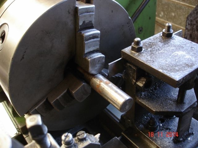
                                          Here's my rear parting tool set up, based on an idea seen in an old copy of Model Engineer. Ian S Cdsc01001 (640x480).jpg

                                          #180333
                                          Martin Kyte
                                          Participant
                                            @martinkyte99762

                                            Exactly Andrew.

                                            That's what I was getting at. Sometimes people need a practical demonstration to convince them rather than just going by the physics. No harm in that and it does not make them any the lesser for it. Generally the practical application gets sorted out long before the theory and we are after all essentially practical people in this game.

                                            Martin

                                            #180339
                                            Gordon W
                                            Participant
                                              @gordonw

                                              I am very reluctant to jump in on this topic, but- . My biggest problem when parting -off does not seem to have been mentioned, so I assume it is not common. Parting is going well, hand feeding. Suddenly the cutting stops, as if a hard part has been reached, the tendency is to put on more pressure and that's when the breakage happens. Now I stop and back off, then restart, usually all goes well. Just working on normal mild steel, sometimes brass and aluminium, never tried stainless so not work hardening. Any ideas?

                                              #180343
                                              Vic
                                              Participant
                                                @vic

                                                What about this type of blade, the chipbreaker?

                                                http://chronos.ltd.uk/acatalog/New–Clamp-Type-Parting-Tool-s-with-Chipbreaker-Blade–5–cobalt-.html

                                                [IMG]http://www.chronos.ltd.uk/acatalog/392685BLADE2.jpg[/IMG]

                                                #180351
                                                KWIL
                                                Participant
                                                  @kwil

                                                  Gordon,

                                                  I think your problem may well be that you are not feeding fast enough for the diameter being cut, you get to the point where you start"polishing". Also as mentioned above the cutting speed changes with diameter, ie it slows, so if you can speed it up, this is where a VFD comes into it own.

                                                  #180352
                                                  Roger Williams 2
                                                  Participant
                                                    @rogerwilliams2

                                                    Gordon W, thats what seems to happen to me as well. Good point !.

                                                    #180362
                                                    blowlamp
                                                    Participant
                                                      @blowlamp

                                                      Maybe it would help to compare a standard HSS parallel (Eclipse style) parting blade to a handsaw without any 'set' on its teeth. Anyone that's tried to use such a handsaw, minus the 'set' that provides clearance for the blade, soon discovers the futility of their actions. So now look straight down at a carbide parting off insert and then along a saw blade and you should immediately see the same 'Y' shape tooth form that creates the kerf gap for chip clearance.


                                                      An Eclipse style of blade completely fills the slot it is making, so it must follow that any chips which aren't physically ejected outwards, will remain within the slot and be constantly enticed by gravity and rotation of the workpiece to work their way down into any nooks & crannies that present themselves between tool and work so provoking a dig in.


                                                      Swarf has a remarkable ability to plug holes and gaps that seem too big to block. Hair and tea leaves blocks plugholes in our house


                                                      Martin.

                                                      Edited By blowlamp on 19/02/2015 12:01:29

                                                    Viewing 25 posts - 201 through 225 (of 291 total)
                                                    • Please log in to reply to this topic. Registering is free and easy using the links on the menu at the top of this page.

                                                    Advert

                                                    Latest Replies

                                                    Viewing 25 topics - 1 through 25 (of 25 total)
                                                    Viewing 25 topics - 1 through 25 (of 25 total)

                                                    View full reply list.

                                                    Advert

                                                    Newsletter Sign-up