Parting Off MEW225

Advert

Parting Off MEW225

Home Forums Model Engineers’ Workshop. Parting Off MEW225

Viewing 25 posts - 151 through 175 (of 291 total)
  • Author
    Posts
  • #179820
    Cabeng
    Participant
      @cabeng

      Here we go again, you ain't got rid of me yet! Chip jamming this time.

      The following comments are for inserted tip parting tools. The only thing I know about parting with HSS is that I haven’t done it for perhaps 25 years – and when I did, I was absolute rubbish at the job!

      A chip jams by welding itself either a) to the sides of the cut, or b) to the tool tip.

      It’s a simple matter to avoid welding to the side of the cut: as often recommended on this forum, use an inserted tip cutter with a precisely formed chip former and chip breaker built into the tip. Chip former to ‘fold’ the edges of the chip away so that they don’t come into contact with the sides of the cut, and chip breaking to curl the chip up tightly so that it doesn’t run across the top of the tool, but breaks off as small curls. Probably #1 Reason why so many model engineers have what can only be described as instant success when they buy one, even though they’ve done nothing else to upgrade their working arrangements and practices.

      So that seems to have sorted that one out, doesn’t it? Unfortunately, not entirely, for two reasons:

      1) The first is that you can adversely influence the effectiveness of chip forming and breaking, by using an unsuitable combination of feed rate and, to a lesser extent, cutting speed. The manufacturer will have designed the tip for a specific material’s chipping characteristics (think of steel and brass), over a particular range of feed rates – your mission, should you choose to accept it, is to find the speed and feed values that suit the tip you have, cutting your material, on your machine.

      Start at a feed rate that gets you just above the gib chatter region (it’s pretty much independent of cutting speed), then work up until you get something like short, curly chips. If you don’t have power cross feed, just wind the handle faster & faster – probably faster than you ever believed you would wind! Then up the speed to improve finish on the parted surfaces – but don’t expect as good a finish as you can get during normal turning. Neither will you get the chip production perfect across the whole diameter, because the cutting speed is reducing as the cut progresses. On the tip I used, 0.004”/rev and 1500 – 2000 rpm gave best results, as low as 250 rpm was ok, but the finish was noticeably poorer. Higher speeds also give better chip clearance – the chips get flung out much faster, but you’ll soon learn to duck quickly!

      Remember that different materials (including different steels) will require different speeds and feeds – one size does not fit all, so you will find different performance on different steels, unless you adjust the cutting parameters. It might sound complicated, but you’ll soon get used it.

      2) Everyone is familiar with the fact that aluminium can stick to the tip of a turning tool. This is because aluminium will weld itself to HSS very easily and at quite low temperatures. Steel and HSS are also quite good at it, steel and tungsten carbide are somewhat less enamoured of each other, steel and titanium carbide (cermet), or coated tungsten carbide, have most resistance to chip welding. #2 Reason why inserted tips are so successful in amateur workshops.

      But none are totally immune, all will join up to some extent if the temperature is right for them. Operate above or below the temperature range and it won’t happen, hit the sweet spot and it can. This means that you have to play your part by operating at a suitable cutting speed, because cutting speed is a major influence on the temperature.

      As mentioned above, the cutting speed inevitably reduces as the cut progresses, and it is possible that somewhere part-way through the cut the temperature falls into the ‘sweet spot’ zone, and something welds to the tip. So having the ability to increase the rpm as the cut progresses can be very useful, another plus point for a VFD.

      Two things happen if something welds to the tip forming what’s called a Built-Up Edge, or BUE:

      Number 1 – the cutting force and tool deflection increases. The effect is measurable by comparing the tool deflection for a new tip and a used one under the same cutting conditions. I was able to do this, and can confirm the effect.

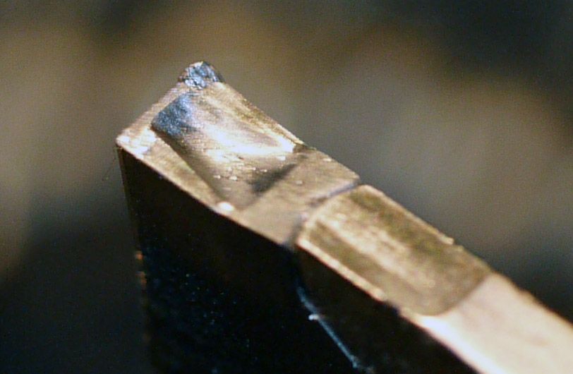
      Number 2 – the form of the cutting edge is changed by the BUE. This has the undesirable effect of changing the chip forming and breaking characteristics of the tip. This photograph shows a bit of BUE on the tip that I used for the parting tests:

      tip bue.jpg

      This after something like 80 parting operations, including stalling the lathe when pushing it at 1500 rpm and 0.008”/rev feed rate. I don’t know when it formed, but I did know exactly when it formed!

      Advert
      #179821
      Cabeng
      Participant
        @cabeng

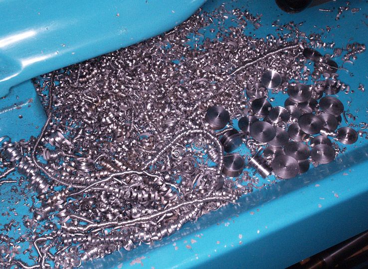
        By which I mean that I don’t know how many parts it had done at the time, but I knew immediately it had happened because the shape and form of the chip changed. Instead of short curls visible under the bed the chip form changed to the spiral chips that can be seen on top of the pile in this photograph that I posted earlier:

        swarf.jpg

        Perhaps surprisingly, it continued to cut nicely, with no tendency to stick to the sides of the cut. As you can see, I did try several times to create a jam, but it wouldn’t, presumably because running at 1500 rpm meant that it was above the ‘sweet spot’ temperature range for steel against steel. Or it could have been below it, I don’t really know, but it flatly refused to jam on the sides of the cut. I guess a more severe BUE, right across the cutting face, would have caused more trouble.

        So take note of the chip form during parting, and if it changes in any way, withdraw the tool and have a very close look at it, to see if it has formed a BUE. If it has, change the tip, or you could be courting disaster, you might not be as favoured by the Gods as I was.

        In my experience, trying to rescue a tip with BUE by cleaning it up with a diamond file doesn’t work. You might get rid of the BUE, but there will be some material residue remaining on the tip that will initiate formation of the next BUE as soon as the tip touches the work.

        Also note that a change in the chip formation can also indicate a tip that’s worn past its sell by date, or worse, broken, so check for those as well. Take Andrew Johnston’s advice, accept that it came with a limited life, that life has gone, so throw it away and fork out some beer tokens for a new one!

        What about use of coolant? I can’t recommend use of coolant with carbide tips, and I don’t use it. Yes, it works, keeps the temperature down, reduces friction between the chip, tool and work piece, and inhibits welding. But with carbides it must be flood coolant or nothing for two reasons: 1) dripping or intermittent coolant can cause thermal shocks in the carbide, leading to cracking and premature failure, and 2) the temperatures involved at the tip result in a lot of fume production from a meagre coolant supply, even if continuous. I don’t know whether or not this is potentially hazardous, so I avoid it entirely, just in case, and cut dry. Which also avoids the mess.

        So there we are – how to part off without parting becoming not-so-sweet sorrow:

        • Get the tool support system in good adjustment, particularly the top slide gib, or use a rear tool post.
        • Consider using a solid tool post at the front – all your turning work will improve, not just parting off.
        • Align the tool perfectly square to the work.
        • Feed at a rate that at least gets you beyond the gib chatter zone, maybe even faster.
        • Invest in inserted tip parting tools to minimize risks of welding & jamming of the chips in the groove, and always have a perfectly designed and formed cutting edge.
        • Keep an eye out for deterioration of the cutting edge, monitor the chip formation and inspect the tip should the chip characteristics change.
        • Find a suitable combination of speed and feed that suits the tip, the material, and the machine. Different material could need a different combination of cutting parameters.
        • But there will always remain a risk that even with a perfectly sorted parting operation, a wayward chip might mechanically jam and cause a dig-in. But there’s nothing to be done about that, it rests in the lap of the Gods.
        • Oh, I forgot to mention, the rear tool post does, of course, assist with chip clearance, particularly when using lower speeds.

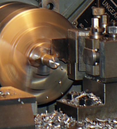
        Two photographs to end with. Rear tool post cutting 5/8” fcms at 2105 rpm, manual feed, note chip formation and clearance:

        rear tool cutting.jpg

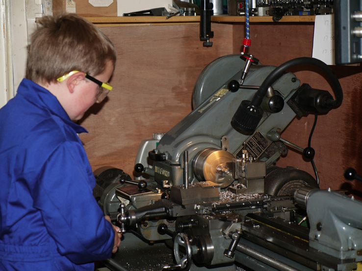
        And here’s the full photograph, showing that if you get everything right, parting really does become child’s play!

        ben parting.jpg

        He was 9 at the time, and had to stand on a perch to get high enough.

        EPILOGUE

        I did say when I started that this would take some time and quite a few postings – I didn’t realise how much time, and how many large postings. I really did try to keep it down, but failed miserably. That was because I felt that some of the things I wanted to put over might not have been accepted without the background information, so it was preferable to put it in now rather than get into long discussions about it later.

        My apologies for that, I do hope that you found it worthwhile, and that it might be of some assistance to you.

        Thank you for you interest and attention, and most of all, thank you for your perseverance!

        #179864
        KWIL
        Participant
          @kwil

          I think all readers owe a debt of gratitude to CABENG for his dedication in getting all of these points across. I for one can concur with everything he says, however I must make myself his version of the front toolpost to complete my experience!

          Bravo

          #179866
          Neil Wyatt
          Moderator
            @neilwyatt

            The thing that strikes me is the complete lack of challenge for Cabeng's work.

            Has he nailed it? Only time will tell….

            Before this started I postulated two opposing ideas for what works: rigiidity and sprung tooling.

            Cabeng has demonstrated that rigidity is one sure route to success, if other things are treated with care.

            I am aware that some deliberately sprung parting tools do work. Can anyone relate experience of using one of these?

            Neil

            #179878
            Michael Gilligan
            Participant
              @michaelgilligan61133
              Posted by Neil Wyatt on 15/02/2015 14:44:16:

              The thing that strikes me is the complete lack of challenge for Cabeng's work.

              .

              Neil,

              I think it's safe to say that is because his descriptions are exemplary, in that they are well-documented, and authoritative. … This thread [or at least the collected writings of Cabeng] should be made 'sticky' as a point of reference.

              As for experience of [intentionally] sprung parting tools, I have none … but I suspect that their success comes from the resonant frequency being shifted down to a band where it is not excited by momentary dig-ins; thus avoiding chatter.

              MichaelG

              #179884
              Michael Gilligan
              Participant
                @michaelgilligan61133

                Posted by Michael Gilligan on 15/02/2015 16:44:44:

                As for experience of [intentionally] sprung parting tools, I have none … but I suspect that their success comes from the resonant frequency being shifted down to a band where it is not excited by momentary dig-ins; thus avoiding chatter.

                .

                [too late to edit my last post]

                … If anyone wants to pursue that line of thinking, this looks a very good place to start.

                MichaelG.

                #179904
                Fatgadgi
                Participant
                  @fatgadgi

                  Neil – yes I made a sprung tool for front parting.

                  When my only lathe was a Myford, parting was a slow affair and every now and then the tool would snag, usually causing the belt to slip (I tended to leave it fairly loose on purpose), but rarely causing more than annoyance.

                  When I got myself a bigger lathe with a 1.5HP motor, snagging also happened occasionally with deep grooves (say 10mm plus cut depth) but the resulting smashed tool was much less fun. The cross slide was not slotted to take a rear tool post so I became paranoid about parting and would avoid it like the plague.

                  Logically slideways must have clearance in be able to move, and logically I would expect movement downwards, towards the the flats (on which the top or cross slides presumably normally rests) to have much more stability than pulling upwards where there is clearance and also a wedge effect. In short, just looking at the geometry of the top slide alone, I decided that the tool would certainly move down and pivot inwards, towards the work, when loaded.

                  So I made a spring loaded tool holder that held a normal HSS parting blade and pivoted away from the work under load which greatly improved things. Basically, it doesn't prevent the occasional snagging, where swarf wedges itself at the side of the parting tool, but it improved the consequences no end. So instead of smashing things, it moved out of the way and cleared itself or at least allowed time to back off the cut.

                  But in all honestly, now I use a carbide parting tool, I rarely have an problem with snagging anyway, so the sprung holder is not used very often. The Carbide cutting edge is wider than the rest of the holder, which I couldn't achieve with the HSS over much length, and the tip is shaped to reduce the swarf width, which I couldn't manage at all.

                  So now I part at a high speed and use a constant dribble of cutting oil in the slot, dispensed from a syringe. I also normally keep the top slide locked, which I suspect helps as well.

                  Cheers – Will

                  #179911
                  Chris Trice
                  Participant
                    @christrice43267

                    A concise and nicely written piece.

                    There is one other factor to consider and that is top rake. A blade set level with the bed and no top rake (as you might use for brass) might not draw the tool into the work but I wonder how much influence a lot of rake has because despite the flow of the chip away from the work, a tool with a lot of top rake must be being drawn into the work by the angle of the forces acting upon it?

                    #179912
                    Chris Trice
                    Participant
                      @christrice43267

                      In fact, thinking about it, who here hasn't had a dig in using the wrong tool (too much top rake) on brass or bronze under normal turning conditions? If using a knife tool right to left, it would suggest that slack in the feedscrew/leadscrew allows uncontrolled movement or there is cumulative slack in the whole system between the bed and the work where the tool overcomes all the forces of friction and mass and draws the saddle in.

                      Edited By Chris Trice on 15/02/2015 23:06:48

                      #179916
                      Cabeng
                      Participant
                        @cabeng

                        Thank you for your kind comments MichaelG – the folding money will be in tomorrow's post!

                        Re the sprung tool – I have a problem with the descriptions of how this works (I do not deny that it does work!), and am surprised to see it in the link that MichaelG posted. My difficulty can be put simply:

                        The cutting force applied to a rigid tool is stated as pulling the tool into the work, whilst that for a sprung tool is stated as pushing it out. For this to be the case, the direction of the cutting force must change – but how does the workpiece know that a sprung tool is in use, and what action does it take to change the direction of the cutting force accordingly? Spooky action at not very much distance! (With apologies to Mr. Einstein.)

                        A speculation on my part, without any evidence at all and applicable to chatter, not dig-in – chatter is vibration, vibration of the tool and its support structure which will occur at a certain frequency, when what happens at the tip resonates with what happens in the support structure. Putting some spring in the system between the tip and the support inserts a different resonant frequency that avoids triggering the support resonance. It could be acting as a mechanical filter, effectively. I stress – pure speculation… Discuss!

                        Neil: I admit to an inherent distaste for sprung tools, as they would introduce variables that would be difficult to control, and inherently introduce non-linearities and dimensional inaccuracy. Dimensional accuracy obviously not important for parting, but as I described re the potential problems during normal turning caused by gib flexibility (a.k.a. a sprung gib!), improving rigidity (if possible) gives improved results all round. And since improving tool support rigidity improves parting as well – why bother with spring tools?

                        Will: would I be right in thinking that your now cutting faster also includes feeding faster? And that chatter (if any) only occurrs on first contact with the work?

                        Chris: I've never experienced what you describe, other than once when I had left the gearbox in screwcutting mode and tried to turn at near 0.040"/rev feed. It didn't like that.

                        #179917
                        Chris Trice
                        Participant
                          @christrice43267

                          I've had it occasionally using the very highly polished silver inserts designed for non ferrous (but ironically wrong for brass and bronze). It was sheer laziness on my part as I couldn't be bothered to change tools. The edges have effectively a very high top rake that can grab in the same way that good quality Dormer drills can grab brass when drilling because the helix angle is very (too) high.

                          #179926
                          Michael Gilligan
                          Participant
                            @michaelgilligan61133
                            Posted by Cabeng on 16/02/2015 01:21:19:

                            Re the sprung tool – I have a problem with the descriptions of how this works (I do not deny that it does work!), and am surprised to see it in the link that MichaelG posted. My difficulty can be put simply:

                            < etc >

                            … Discuss!

                            .

                            I don't "have the maths" to do justice to this; but here is the gist of my thinking:

                            In creating a 'sprung' tool, we are introducing a local compliance into a [much more] rigid system. This has some significant effects.

                            1. If we could quantify that compliance, it might simplify the [first order] analysis.
                            2. The resonant frequency is lowered, and, most importantlay
                            3. The 'Q' of the resonance is greatly reduced.

                            Chatter occurs at high audio frequency when a 'rigid' tool goes into resonance … The high 'Q' means that once it does start, it is difficult to stop.

                            By contrast, the graph for resonance of a 'sprung' tool will be much broader, with a much lower peak.

                            I suspect that the tip of a sprung tool is almost immediately dragged [minutely] downwards by the cutting action and remains in that half of its oscillatory pattern …. Whereas the rigid tool, because of its high 'Q' will go into resonance.

                            Most of us will have [perhaps unwittingly] used a sprung tool, in the form of a slender Boring Bar … we know that the sizing cuts have to be repeated, to 'work the spring out of the tool' … and therein, I think, lies the explanation for the success of Swan Neck and similar tools.

                            MichaelG.

                            Edited By Michael Gilligan on 16/02/2015 08:15:36

                            #179932
                            Russell Eberhardt
                            Participant
                              @russelleberhardt48058
                              Posted by Michael Gilligan on 16/02/2015 08:15:10:

                              1. The 'Q' of the resonance is greatly reduced.

                              Not sure about that bit Michael. The Q is the ratio of energy stored in the resonant system to the energy lost per cycle. Why should lowering the frequency reduce the Q? Are you suggesting that perhaps the springy part has additional friction built in?

                              Just curious.

                              Russell.

                              #179938
                              Michael Gilligan
                              Participant
                                @michaelgilligan61133
                                Posted by Russell Eberhardt on 16/02/2015 09:05:52:

                                Posted by Michael Gilligan on 16/02/2015 08:15:10:

                                1. The 'Q' of the resonance is greatly reduced.

                                Not sure about that bit Michael. The Q is the ratio of energy stored in the resonant system to the energy lost per cycle. Why should lowering the frequency reduce the Q? Are you suggesting that perhaps the springy part has additional friction built in?

                                Just curious.

                                Russell.

                                .

                                Russell

                                As indicated … I do not "have the maths" but:

                                From practical experience in vibration testing, it appears generally true that [assuming that the masses, mateials and dimensions remain constant] a structure with a lower resonant frequency will have a lower 'Q'. … A given 'g level' at low frequency involves much greater displacement, and a high 'Q' at a low frequency would presume a higher mass.

                                You will see that I am struggling here … hopefully someone can either support or disprove my hypothesis by providing some proper analysis.

                                MichaelG.

                                #179947
                                Mark C
                                Participant
                                  @markc

                                  Michael,

                                  Don't be hard on your lack of "the maths" for this one. The assumptions that have been made, and they are at best only a guess in the main, take no account of the complex interactions of the loads and materials involved. I thought it might be interesting to try simulating the assembly (I have the software) as it is on my lathe but it is proving very difficult. Part of the problem is the process comprises a system involving non-linear plastic behaviour mixed up with frictional and elastic reactions in a dynamic process. The whole thing forms a very complex arrangement if you want to start looking at it properly and if not then you are really only guessing and speculating. Trying to measure the loads using a lever and some weights is likely going to lead you up the garden path as you have to start making assumptions which is problematic as you don't know for certain what is going on in the first place. If you really want to know what is happening by measuring, you might try adding strain gauges and directly measuring the loads which may allow you to reasonably judge the loads being seen by the bulk of the "system" but then ensuring there was no coupling of transducers might prove interesting in its self!

                                  Mark

                                  #179956
                                  Chris Trice
                                  Participant
                                    @christrice43267

                                    I'm tempted to try the holder in the article. If it works, that in itself will indicate what might be going on and how much each aspect plays a part.

                                    #179959
                                    Fatgadgi
                                    Participant
                                      @fatgadgi

                                      Hi Cabeng

                                      The sprung tool that I made was not like the swan-neck variety. Because I wanted to control the geometry and I had no idea how the spring system would behave or whether it would work at all, I made the tool holder part of a pivoted swinging arm and added an adjustable compression spring. The tip definitely swings down and out by a meaningful amount when it needs to as the pivot is close to the front and higher than the tool.

                                      In terms of chatter, with the current lathe it's not a problem. I'm sure that I have had chatter at some point when starting, but I cannot recall a specific event so it's rare.

                                      I do not use auto feed with the Carbide tool. I like to control the cut by feel and keep the chip constant (I think deep down I am still psychologically damaged by early attempts), but I do feed at a reasonable rate, yes. When I first made the swing tool I did play around with it extensively and I used the auto feed sometimes then, primarily to see if the constant feed would help things.

                                      Cheers Will

                                      #179960
                                      Ian S C
                                      Participant
                                        @iansc

                                        It might be best to remember that when the swan neck/spring tool was first used the average lathe tool was made from tool steel, and the lathe would have been run much slower that if using HSS, HSS in those days was looked on as carbide is today compared to HSS.

                                        Ian S C

                                        #179965
                                        blowlamp
                                        Participant
                                          @blowlamp

                                          It seems to me that the Swan-neck tool is meant as a kind of safety valve in the event of a lock-up occurring. To my mind it therefore follows that this tool doesn't tackle the real issue, which is one of alleviating the conditions that allow lock-ups to happen.

                                          I can't think of any commercially available tool that uses the Swan-neck principle to circumvent parting off problems.


                                          Martin.

                                          Edited By blowlamp on 16/02/2015 11:12:26

                                          #179970
                                          Muzzer
                                          Participant
                                            @muzzer

                                            Sit back in your armchairs and see what Google comes up with for "machine tool chatter thesis". It's not a black art although it's a little more complex than what the tool holder is made of. There is both the local cutting process itself and the whole system (the rest of the machine) to consider. You can't expect to intuit the whole thing – if you do you are going to be disappointed.

                                            Bottom line is, set the machine up carefully (well adjusted, minimal overhang, tight gibs, saddle tight or locked), use nice solid tools (rigid tool post, inserts!), feed adequately and consistently (power feed!), find a region that is chatter free on your machine (experiment with speeds and feeds) and note the settings that work. It's mostly good sensible practice and evidence-based learning.

                                            If you still don't like parting off, use a saw!

                                            Merry

                                            #179972
                                            WALLACE
                                            Participant
                                              @wallace

                                              Also… a sharp tool !

                                              I used to sharpen my blades very crudely on a bench grinder – hand held as well…

                                              Parting off become a lot less stressful when I started to grind them up properly !

                                              W.

                                              #179976
                                              blowlamp
                                              Participant
                                                @blowlamp
                                                Posted by Muzzer on 16/02/2015 11:58:04:

                                                Sit back in your armchairs and see what Google comes up with for "machine tool chatter thesis". It's not a black art although it's a little more complex than what the tool holder is made of. There is both the local cutting process itself and the whole system (the rest of the machine) to consider. You can't expect to intuit the whole thing – if you do you are going to be disappointed.

                                                Bottom line is, set the machine up carefully (well adjusted, minimal overhang, tight gibs, saddle tight or locked), use nice solid tools (rigid tool post, inserts!), feed adequately and consistently (power feed!), find a region that is chatter free on your machine (experiment with speeds and feeds) and note the settings that work. It's mostly good sensible practice and evidence-based learning.

                                                If you still don't like parting off, use a saw! carbide insert tool, preferably with positive rake geometry designed for smaller lathes & gentle cutting forces.

                                                Merry

                                                !!!^^^^^^^^^^^^^^^^^^THIS^^^^^^^^^^^^^^^^^!!!

                                                (My changes & emphasis to Muzzers's text in BOLD and UNDERLINE) smiley

                                                Martin.

                                                Edited By blowlamp on 16/02/2015 12:36:19

                                                Edited By blowlamp on 16/02/2015 13:03:53

                                                #179977
                                                Michael Gilligan
                                                Participant
                                                  @michaelgilligan61133

                                                  Martin,

                                                  May I suggest that you add your "BOLD and UNDERLINE" to the closing words of you ammendment.

                                                  MichaelG.

                                                  #179978
                                                  Neil Wyatt
                                                  Moderator
                                                    @neilwyatt

                                                    Parting is such sweet sorrow that I’ll keep trying until tonight becomes tomorrow

                                                    Will.

                                                    #179979
                                                    blowlamp
                                                    Participant
                                                      @blowlamp
                                                      Posted by Michael Gilligan on 16/02/2015 12:50:29:

                                                      Martin,

                                                      May I suggest that you add your "BOLD and UNDERLINE" to the closing words of you ammendment.

                                                      MichaelG.

                                                      I've tweaked it a bit to make my additions a little clearer.

                                                      Martin.

                                                    Viewing 25 posts - 151 through 175 (of 291 total)
                                                    • Please log in to reply to this topic. Registering is free and easy using the links on the menu at the top of this page.

                                                    Advert

                                                    Latest Replies

                                                    Viewing 25 topics - 1 through 25 (of 25 total)
                                                    Viewing 25 topics - 1 through 25 (of 25 total)

                                                    View full reply list.

                                                    Advert

                                                    Newsletter Sign-up