Parting Off MEW225
Parting Off MEW225
Home › Forums › Model Engineer & Workshop › Parting Off MEW225
- This topic has 290 replies, 41 voices, and was last updated 28 February 2015 at 12:22 by
Mark C.
-
AuthorPosts
-
10 February 2015 at 18:01 #179243
 Michael GilliganParticipant@michaelgilligan61133Posted by JasonB on 10/02/2015 16:20:11:
Is the win just to cover the cost of the tooling or will you be buying a ridgid machine to make the most of it
.
A decent win would comfortably cover both
… We can but dream !!
More realistically; it would be nice to try some of their small tools on the Pultra.
MichaelG.
10 February 2015 at 23:19 #179283Anonymous
Posted by Vic on 10/02/2015 17:40:52:Unthinkable practice for those folks with Harrison's etc

Andrew
11 February 2015 at 16:23 #179377Cabeng
Participant@cabengApologies for being a bit tardy with Part 3, but wotsername got badly hit by an infection a couple of days ago, so it's been a round of doctor & hospital visits. Which continue, and may delay further postings a bit.
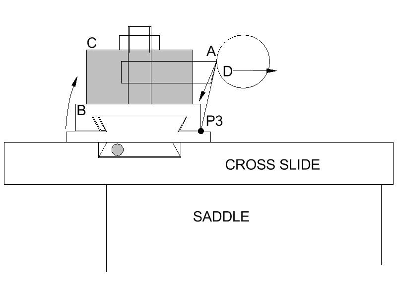
Yet another sketch to start off with:
Once again not to scale, but the top slide etc. are sitting in about the right position relative to the saddle.
The force at the tool tip now pushes the tip down, and since the tip is out-board of the top slide base, it exerts a turning moment trying to tip the top slide over. In this case, the pivot point is obvious, it’s at P3, the in-board edge of the top slide. We now need to look at what resists this turning moment, attempting to keep the tool tip stable relative to the work.
The obvious answer to that question is the gib strip, i.e. not very much! Just a floating strip of steel, held lightly (it has to be lightly, or the slide wouldn’t slide) against the inner vee of the base, located laterally and vertically by four round-nosed grub screws pushing into shallow dimples in the gib strip. Since the assembly bears the same relationship to rigidity as blancmange does to concrete, one might expect it to deflect when a load is applied to the tool tip. And it really does deflect:
LOAD (lbs)
A
B
C
D
E
72
-18
+5
+5
2
+15
92
-22
+6
+5
3
+20
164
-30
+15
+10
5
+26
Units for deflections are again 0.0001”, for A, B, C & E negative numbers are down movement, positive numbers are up. D is inward movement of the tool tip. I tried to keep the loadings the same as for the rear post, but they’re probably a bit different, perhaps slightly higher.
Some of the results might not seem to be consistent with each other, that’s for two reasons: 1) the readings for A, B, C & E are all vertical, but they’re not coplanar, and 2) it’s a complicated situation with things bending, tilting & twisting all over the place!
As far as the inward movement of the tool (D) is concerned, it's very low, but I'll deal with that later, if I may.
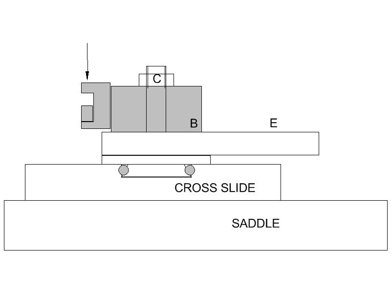
Before that, where is measurement E taken? Sketch:

E is the back end of the top slide. The cutting load, being outboard to the left of the circular base, causes it to lift. Quite possibly this is not just down to the gib strip, but also by lifting of the right hand side of the dovetail spigot securing the top slide to the cross slide, pivoting about the point where the front edge of the top slide base meets the cross slide.
This upward movement of the back end, and the corresponding downward shift of the tool tip, and both are BADLY affected should the top slide be extended off the base, towards the headstock. My tests were undertaken with the top slide arranged as shown above, i.e. NOT overhanging the base.
So what have we got? The tool load causes the slide part of the top slide to pivot inwards about P3, movement allowed by the gib strip allowing the operator side of the slide to lift. The cantilever load on the tool on the headstock side of the base pushes down and lifts the tailstock end, gib strip flexure again, probably augmented by movement in the circular dovetail spigot. The Dickson block moves differently to the top slide on which it sits, presumably as a result of stressing of the holding down bolt. Oh yes, let’s not forget the tool holder and the tenon bolt that holds it to the main tool block.
<I have right clicked on the table and selected table properties and set the width to 512 – Neil>
Edited By Neil Wyatt on 11/02/2015 17:53:13
11 February 2015 at 16:25 #179379Cabeng
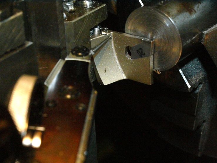
Participant@cabengGiven that my loading system was vertically down on the tool, and not inclined as in reality, the static measurements of inward tool movement D must be regarded as marginal as far as coming to any firm conclusions is concerned. To resolve the matter I did some dynamic tests, measuring the in/out movement whilst actually parting off. The photograph shows the position at which I set the indicator to ‘measure’ this movement.
Now before I go further, I am well aware that some might find some of the information, some of the measurements, and some ‘details’ of the cutting tests that follow, to fall somewhere between surprising and unbelievable.
The measurements etc. might not be ‘accurate’, due to their rather crude nature, but they are certainly … what shall we say… indicative?… of the right order?… in the right ball park?…. representative of the situation? Choose whichever one you like! But they are REPEATABLE, plus or minus a bit, and that’s important. Because I’ll be more than happy to demonstrate them, and the turning tests, to anyone who wishes to view them. So if anyone lives convenient to the Chester area and wants to come round, have a look, and verify them on behalf of other Forum participants, just let me know.
Right, dynamic (cutting) tests using the front tool post on a top slide that flexes as shown in the above table, using power cross feed. The saddle was NOT locked to the bed, the indicator was mounted on the cross slide so that it could track with the tool…
The tool moves OUT from the work at lower loads (0.002”/ rev) by <= 5 tenths. And why should we not be surprised by this? Look again at my second sketch at the start of this series – look at the direction of the force applied to the tool tip – it’s down & OUT.
Does a higher feed rate change the ‘out’ movement? Yes, it does, but with increased feed, the OUT movement increases, 0.003”/rev shoves it out by about one thou.
Can it be made to go ‘down & in’ at higher loads? No. OUT at 0.004”/rev, OUT at 0.006”/rev, OUT at 0.008”/rev, but not for long at that feed because the lathe spit out it’s dummy, stalled, and ran home to mummy, whilst wiping the tears from its eyes! Well, taking that cut at 1500 rpm does calculate out at 2.6 h.p.!
So yes, that’s front tool post, Iscar parting tip, 19mm bar, 2mm wide cut, 0.006”/rev, 120 metres/min, 1500 rpm, 2.14 h.p. (calculated, not measured), using the top slide and front tool post, power feed. No chatter, no ‘down and in’, all ‘down & out’.
And perhaps more surprisingly, I normally part of 1” bar at c. 2000 rpm, 0.002”/rev, but had to slow down a bit as 2000 rpm didn’t give me enough time to observe the indicator reading before the end dropped off the bar!
Parting off problem? What parting off problem would that be?
OK, could it be the chatter, jamming and dig in problems? Unfortunately, in trying to resolve these problems, model engineers have been looking in the wrong place for decades, and consequently haven’t found the real answers. They’ve been led up the garden path by the ‘Four Theories’, which my tests have examined in more detail, and shown to be false premises – I hope you agree with that claim, so let’s just recap on where we’ve got to!
11 February 2015 at 16:25 #179380Cabeng
Participant@cabengSummary to date:
For a machine in good condition, with well adjusted slides (and if it doesn’t fit that description, all bets are parted off):
1) The conjecture that saddle lift helps a rear tool post can be dismissed – at the tool loadings we’re looking at it doesn’t (o.k., shouldn’t!) happen.
2) The ‘up & out’ behaviour isn’t confirmed in my tests, so I’ll consign it to the WPB (Waste Paper Basket).
3) The top slide does deflect more than the rear tool post, but the ‘down’ movement does not result in any ‘in’ movement, it is in fact ‘out’ movement, because of a) the complex nature of the top slide assembly and its correspondingly complex movement in many directions, and b) the direction of the force on the tool tip pushes it out. So this one’s headed for the F+F file (File & Forget)
Which leaves just one other ‘reason’ for rear parting off, the one about the rear tool post pushing the spindle down into the strong part of the headstock, whereas the front post pushes it up towards the weaker bit. Well, if anybody designed a lathe where an upward load on the headstock bearings was a limiting factor, they’d be a very poor designer of lathes! That’s obvious enough, but additionally, consider the following:
The 92lbs. load I applied to the tool posts corresponds to parting with 2mm (0.080" ) wide tool at a feed of 0.06mm (0.002" ) per revolution. But that is exactly the same tip loading that would be experienced when TURNING at those values, and an S7 wouldn’t even work up a sweat doing that! The 164lbs. load corresponds to 2mm (0.080" ) depth of cut, with the feed rate increased to 0.13mm (0.005" ) /rev., still within its capabilities. Those loads would be applied upwards at the headstock, just as parting off from the top slide does… and since it’s perfectly capable of taking the turning loads and surviving for years, why should a bit of parting off in the front tool post cause it to get its knickers in a twist? So:
4) Spindle load down instead of up? Definitely one destined for the LTU (Laugh & Tear Up) file.
So where do we go from there? Tune in next time to find out! And find out why the rear tool post IS better for parting off. And what to do about the topslide. And.. other things as well.
Edited By JasonB on 11/02/2015 16:37:57
11 February 2015 at 16:28 #179381Cabeng
Participant@cabengWould it not be a GOOD IDEA to completely remove those bloody smilies from this editor, preferably using EXTREME VIOLENCE!?
11 February 2015 at 20:54 #179415Cabeng
Participant@cabengThanks for the edit Jason.
11 February 2015 at 22:38 #179431Chris Trice
Participant@christrice43267A very good set of posts Cabeng. Each weak spot might make a miniscule difference but the cumulative effects add up.
If there was zero flex in the whole system, we'd be picking up broken bits of parting off blades everytime there was a jam (belt slippage not withstanding).
Edited By Chris Trice on 11/02/2015 22:38:51
11 February 2015 at 22:55 #179433 Michael GilliganParticipant@michaelgilligan61133
Cabeng,
Excellent work … Many thanks for taking the trouble to share it.
MichaelG.
12 February 2015 at 09:07 #179453Martin Kyte
Participant@martinkyte99762Hi Cabeng
Looks like we are getting somewhere now you have established what happens when the system works as it should.
It would be a good next step to consider what one would need to do to make it not work. If you need a refresher of tool cutting forces and you probably don't run the clip at
http://www.learnengineering.org/2013/01/cutting-force-analysis-merchant-circle.html
It should be clear that the vector force you show in your first sketch at A which you call force at the tool tip can change with tool tip geometry, material metallurgy and inward cutting force applied to the tool tip the combination of which will change the angle of the vector. If this is sufficient to bring the vector inboard of your pivot point P3 then we are back to a positive feedback state and potential trouble.
A couple of notions do occur to me.
1. Keep the normal force (pressure on the tool) high enough which should tend to move the vector in the outboard direction.
2. Don't grind to great a top rake as this will move the vector in the inboard direction.
Anecdotally this would seem to tie in with the experience of having less problems with 'confident cuts'
I would be interested in your comments.
regards Martin
12 February 2015 at 10:07 #179461Chris Trice
Participant@christrice43267If we look at the design of the tool holder in the article which started this thread, it doesn't require the necessity to ride that knife edge of balancing negative and positive forces by feed rate.
12 February 2015 at 10:28 #179465Cabeng
Participant@cabengI've been reluctant to respond to other postings on this subject up to now, for two reasons:
1) It's taking enough time up to re-do the tests, prepare sketches, and take photographs – I personally didn't need to do this as I did it all … oooh… twenty years or so ago, but lost the notes and didn't take photographs at the time! And I thought that as some of it might turn out controversial, I needed to present the whole story, together with real evidence, so I ended up re-doing everything. But the time being taken is actually the secondary reason, the primary is:
2) It's all going to come out in the wash, so I don't want to pre-empt what's to come, and risk presenting information in an out-of-sequence and disjointed fashion.
However, I think it's now safe to respond to Kiwi Bloke, Chris Trice & Martin Kyte – but it will have to be this evening, as I must now take wotsername for yet more blood tests, and then I have someone coming round for the afternoon.
And if anyone else has a question… get it in before this evening!
12 February 2015 at 10:50 #179472 Michael GilliganParticipant@michaelgilligan61133
Posted by Michael Gilligan on 21/01/2015 18:50:55:
… I think the main cause of problems is that the top-slide introduces another layer of flexibility.
….
P.S. … The Gibraltar ToolPost looks a very sensible design … Can anyone offer a review?
.
Cabeng,
May I take-up your invitation, and ask you to have look at the Gibraltar ToolPost, referenced earlier.
My instinct tells me this would overcome many of the difficulties that people experience with the ML7, but it would be good to see this confirmed [or disproved] by your analysis.
I hope all goes well for you.
MichaelG.
12 February 2015 at 11:15 #179477 Russell EberhardtParticipant@russelleberhardt48058
Thanks, Cabeng, for taking the time to share this and and best wishes to "Wotsername" for a speedy recovery.
I used to think that the design of my Atlas top-slide, with the gib strip on the spindle side, was wrong but looking at your diagram and considering the forces perhaps it is better than the Myford arrangement?
Russell.
Edit to correct spelling.
Edited By Russell Eberhardt on 12/02/2015 11:15:49
12 February 2015 at 11:18 #179478Anonymous
Posted by Martin Kyte on 12/02/2015 09:07:33:Anecdotally this would seem to tie in with the experience of having less problems with 'confident cuts'
Exactly, a whole load of problems go away for both turning and milling with proper feedrates, and to a lesser extent, surface speeds. Oh, and cutters are a consumable item, use them and then sharpen or throw them away. Don't faff around with teeny weeny feeds and speeds to 'prolong' the cutter life, because it doesn't.
I have never, ever, experienced any kind of positive feedback when turning; it might exist in theory, but I suspect it is not an issue in practise.
Andrew
12 February 2015 at 13:27 #179494Muzzer
Participant@muzzerBTW, you can get a Korloy parting blade with 20 inserts for £69 at the moment, which seems like a good deal. Beats glass-like HSS parting blades hands down for resistance to breakage. 2mm width would probably work well for Myford-class machines.
You'd need a holder for it but a block of steel and a couple of bolts is a simple solution to that. You could even operate it upside down if that works for you….
12 February 2015 at 14:56 #179501KWIL
Participant@kwilBTW Korloy 3mm wide blades are OK on a Myford S7, I use both 2 & 3mm, As always you need to keep the infeed rate up to ensure proper operation (unless you think you can part by polishing the surface!).
Now to "upset" some, I rarely used the topslide at 90 degrees to the cross slide as per illustrations, it spends its time set to whatever thread half angle I was last using, that is not a problem either.
Thanks to CABENG for closing down most of the opposing views.
12 February 2015 at 23:56 #179564Cabeng
Participant@cabengChris:
If there was zero flex in the whole system, we'd be picking up broken bits of parting off blades everytime there was a jam (belt slippage not withstanding)
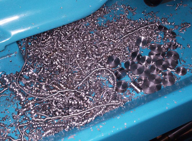
Not if we avoid jams in the first place! Here's the residue of about 50% of the tests, there's something like 40 cuts there (some of the bits have multiple grooves), all using the same tip and not a single jam up for the whole 100%:
P.S. – can we have a whip round for some replacement 19mm bar, please?!
Martin & Andrew – I agree with Andrew, positive feed back from the cutting forces, if it occurs, would be well outside our performance envelope. However, the jam-up scenario could be described as positive feedback, but it has specific causes, which will come later. But it's not from the cutting forces.
MicahealG: some comments re. solid front posts in the next chapter, which is nearly ready for posting. They work very well indeed, better than a rear tool post, and do indeed overcome the problems discussed to date, as well as others that result from gib flexing during normal turning.
Russell: that's an interesting design, and would overcome any lifting of the gib side. But… the solid side of a slide can be considered to be the 'master' side, the one that provides the location in two planes. With an outboard gib the cutting forces push outward on the tool, and on the slide, forcing the 'master' faces into contact, but easing pressure on the gib. With an inboard gib, the forces would push the gib into harder contact but would ease the now outboard 'master' side, and allow it to lift until the 45 degree surfaces came back into contact. Would this be better or worse than the conventional outboard gib? The unhelpful answer is that I don't know the answer! But it should be easy enough to check, by turning my top slide round and applying some load. I'll have a look at that, it could be interesting!
Muzzer: that's an absolute bargain, bite their hand off! Most of my parting is done with that type of tool, albeit the Iscar version.
KWIL: A 3mm tip will produce 50% more cutting force than a 2mm tip. I suggest keeping the width to the minimum required, usually determined by the diameter to be parted off – the wider the blade, the more overhang it can accomodate. 2mm is the widest I find need of, most parting uses a 1.6mm tip, and I have some 0.75 and 0.5mm wide tips for small work. Those little ones are an absolute delight to use but unfortunately they have limited diameter capability (about 6mm), and are very delicate – I break more than I wear out, usually by knocking them with some tool or other. But great for making run-out grooves on small threaded components, or parting off a drilled component of around 3mm wall thickness.
Andrew: cutter life – seconded, 100%
13 February 2015 at 16:24 #179648Cabeng
Participant@cabengHere we go again, but no sketch this time, just verbage & one photograph!
It should now be apparent that we are dealing with a complex mechanical system, with many variables, any detail of which can adversely affect the results of parting… and I’m only dealing with tool support systems here. each variable got right, in a logical and methodical manner, whilst and avoiding false assumptions.
So first eliminate everything you can – slide adjustment, obviously, but also little details like swarf trapped under a tool post, or dings and burrs on the top slide. They prevent metal-to-metal contact over the full available area, and add more flexibility and unpredictability into the system. Make sure the tool post bolt is vertical in both planes so that the tool post sits flat, and the tool post is either a good fit on the bolt, or sleeved to fit, so that it can’t shift around on the bolt.
Then understand what’s going on when the top slide and tool post come under stress, so to that end let’s think about what might be happening with that gib strip under a range of loading conditions – let’s designate them as light, intermediate and heavy.
Light: small depth of cut and feed, low tip load, gib strip very lightly loaded, virtually undisturbed, it’s life is comfortable and all proceeds normally. Probably only applies when scraping a thou or two at low feed, with a sharp cornered tool – it wouldn’t take much of a tip radius to increase the load sufficiently to get the gib into:
Intermediate: moderate tip load, gib under some stress, operating in what we could call its ‘squashy’ mode. Any variation in tip load will disturb it one way or another from its mean position, the tip will wobble about a bit and not be stable relative to the work. An alternative designation for intermediate mode could be ‘chatter mode’, for reasons that I think you will find obvious.
Heavy: some serious cutting work now, the gib is fully disturbed, by which I mean that all flexibility has been taken up by the forces at the tool tip, and it’s locked up solid. The tip position is stable relative to the work, variations in the cutting load do not result in its position changing. Please note that here I’m only considering the behaviour of the gib strip, not the other components of the tool support system.
I suggest that getting the gib into the chatter mode accounts for the chatter part of the parting problems, because due to the width of a parting tool it would be very unlikely that light mode would ever be experienced – one touch from the wide tool and the jib goes straight into chatter mode. Then it all gets exacerbated by the driver, who hears chatter start and backs off. Then re-approaches gently, and it starts to chatter immediately, as the tip gets rattled about by the previously engraved chatter markings, and it just seems to go from bad to worse.
So the answer to chatter when parting is to load the tool up more so that the load takes the gib strip into ‘heavy’ mode, where it’s stable. If it chatters, don’t back off, but speed up. This provides the rationale for the success of two techniques that have been described in this topic:
1) Use power feed – manual feed will inevitably result in variations in the depth of cut, and therefore the tip load, giving unstable conditions and risking the gib going into chatter mode, perhaps when the driver is changing hands. Power feed will be constant, much more stable, and will typically feed at a minimum of 0.002”/rev (which I find to be a satisfactory rate), which is equivalent to:
2) Feed faster – greater depth of cut, higher tip load, forces the gib strip into ‘heavy’ cutting mode where all play has been taken up, so stable cutting conditions with no further deflection. If no power feed, just wind the handle faster, and keep it as smooth as possible.
Now it must be said that the gib behaviour I’ve described is NOT proven beyond doubt, for that one would have to do a lot more detailed work on the gib itself, and such work is beyond any facilites available to me. I would like to think that it’s not just mere conjecture, perhaps ‘rational explanation’ of what could be happening might be the appropriate terminology. There is further support for the theory, as it also explains three other situations that you will probably have come across during normal turning. These are:
13 February 2015 at 16:25 #179650Cabeng
Participant@cabengQ1) You take a ‘decent’ cut down a bar, then wind the saddle back without retracting the tool, and get a left hand screw thread formed on the work.
A1) On the ‘decent’ cut the tool tip was deflected down and out, and cut a larger diameter than you expected, on the return path the flexure had gone, and the tool tip was able to form the pretty (or should that be ‘pretty annoying’?) pattern.
Q2) Making say six parts to the same diameter, taking say 0.080” off the stock. You work down to diameter carefully, frequent micrometer checks to see where you are up to, final cut to size say 0.003” deep, spot on, set the micrometer dial to zero, or the DRO to diameter, and make the next one using those settings, but going down to size in two equal cuts of 0.020”/0/020” – and the size comes out wrong!
A2) The DRO or dial thought it knew where the tool tip was, but the top slide had flexed more with the heavier cut, and fooled you by shifting the tool tip away from where it ‘should’ have been. The solution is to always take the final cut on the subsequent parts at the same depth of cut used to bring the first part to diameter, so cut at 0.020”/0.017”/0.003” instead of 0.020”/0/020”.
Q3) Having cut the stock to near finished size without any problems, you take the final cut at two or three thou. and the d**n thing chatters and wrecks the job!
A3) The roughing cuts had the gib in ‘heavy’ mode, the light cut let it drop down into the ‘chatter’ region.
So what can be done about it? Well, if you’re using the top slide… nothing that I can think of! You’ve just got to live with the behaviour, understand it, and work around it. Or use something more rigid to support the tool system, such as the rear tool post – and by now it should be obvious why this works better: it’s a more rigid structure. It’s as simple as that. A bit if chatter is still possible, because of lifting of the cross slide, but in my experience it’s significantly less of a problem than with a top slide. And, of course, it’s lifting against a block gib, securely bolted to the cross slide
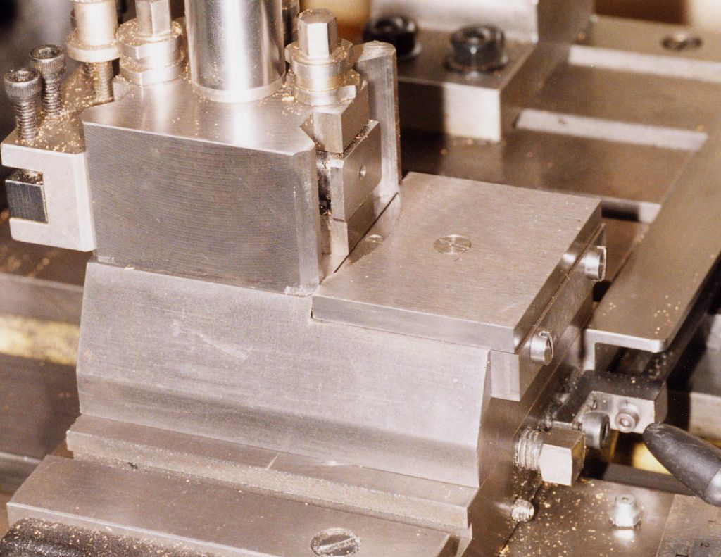
But I do think that the front position is the best option, if the flexing behaviour can be overcome, because the forces are directly down into the bed, and lifting of the cross slide is also eliminated. For that you need something like Tubal Cain’s Gibraltar tool post, or Neil’s solid support block. I’ve no experience of those specific units, but this is my version on the theme:
It works very well, and I can be 100% confident that the Gibraltar would work at least as well. You will be surprised at the cutting capability of an S7 with such a tool support system. And in addition, you will eliminate the Q1, Q2 and Q3 problems described above.
A further improvement to mine and the Gibraltar would be to extend the base in and out to cover the adjacent tee slots, and provide two bolts in each ‘wing’ of the base, thereby eliminating any weakness connected with the dovetail spigot. Just like John Radford did, heaven only knows how many years ago. Have a look on the Hemingway site, Tool Holding & Positioning/Myford Specific Items/Improved Top Slide to see what it looks like – it’s beyond me why Myford never took this up!
Oh, if you do look at that, you’ll see that Radford fitted his top slide gib with a locating dowel and slide lock, exactly as GHT did – but who had the original idea?! I have that on my S7 top slide, and it certainly makes a difference to adjustment and smoothness of the top slide, but does it solve the gib flexing problem? Well, I’ve tested it, and unfortunately the answer is a definite no, not a bit of difference, I’m afraid. Locking the gib at one point only, roughly in the middle of the gib, still leaves the end under the tool post free to move.
A solid front support does work better than the rear tool post. But despite that I still use the rear post, because it has a significant advantage: the front position is where all the ‘normal’ tools go, and their support system (4-way turret, Dickson tool post, Aloris, etc.) frequently gets twisted around, so every time a parting tool is required, it has to be clocked true. And if that’s not done, and it’s even a little bit off-square, you end up with additional unknown/unpredictable behaviour. With the rear post the parting tool can be set accurately to centre height and accurately SQUARE to the work, and then just left there, ready when needed.
An obvious difficulty of all solid front supports is that there’s no feed screw with micrometer collar, but if you have a DRO fitted, who needs a micrometer dial? Put the top slide away, and keep it for turning short tapers. And if you haven’t got a DRO… well, you can work out for yourself what needs to be done!
I hope that’s explained chatter adequately, and provided some indications of how to deal with it. In the next chapter I’ll look at my conclusions re. jam-ups and dig-ins (yes, they can still happen), how they happen, why they happen, and how to avoid them. Most of the time, but not always!
13 February 2015 at 16:41 #179651 Michael GilliganParticipant@michaelgilligan61133
Superb summary, thank you.
MichaelG.
14 February 2015 at 01:13 #179701Cabeng
Participant@cabengRussell:
I've done the tests applying loads to the gib side of both the S7 and Connoisseur top slides. I had to use a slightly different set up, so I can't be sure that the results are strictly comparable. That said, the tool deflections reduced by about 50% when loading the gib side, so perhaps Atlas knew a thing or two that other makers didn't!
14 February 2015 at 05:44 #179704WALLACE
Participant@wallace….best option I’ve found is to just use a hacksaw…..

W
14 February 2015 at 09:08 #179711 Michael GilliganParticipant@michaelgilligan61133Posted by WALLACE on 14/02/2015 05:44:45:
….best option I've found is to just use a hacksaw…..
W
.
Dare you post photos of your lathe bed

MichaelG.
14 February 2015 at 10:34 #179723Cabeng
Participant@cabengWe must first answer the Chicken & Egg question – which comes first? Dig-in then jam, or jam then dig-in?
Well, since I haven’t found any reason re tool post behaviour as to why a dig-in should occur when a parting tool is cutting normally, I reject that sequence of events, and choose the jam comes first, followed by the dig-in, option. So can I suggest a mechanism for this sequence? Yes, I can.
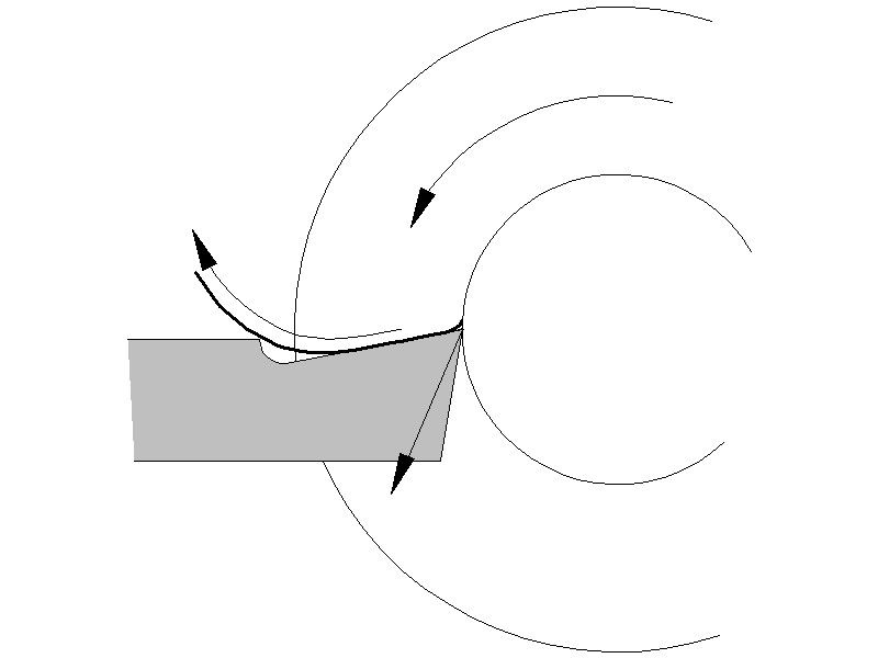
The following sketch shows a section through a parting off operation – let’s assume 1” bar, 500 rpm, tool half-way through the cut, so tip at 0.25” from the centre line:
The chip is flowing over the rake edge, then being curled up a bit by the step to full tool height. The tip experiences the cutting force, which is pushing the tip down and out, but as we have seen, this is ok, the tool support structure can hack it. But should that chip jam by either seizing to the tool, or seizing to the sides of the cut, we enter a very different situation.
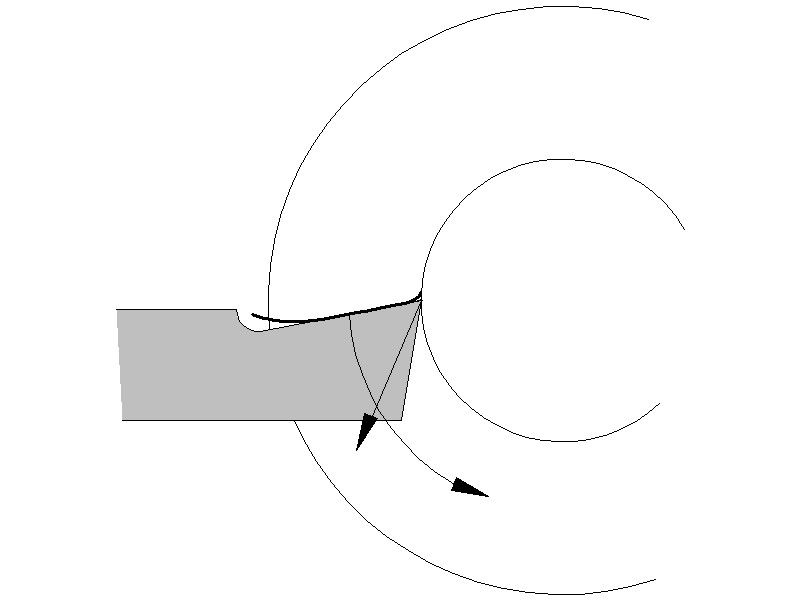
So what does the motor do? First, let’s assume there’s no belt slip to think about, i.e. we’re working on the world’s only direct-coupled geared-head S7! The gearing is set to produce 500 rpm at the work, and it’s using about 0.25 h.p. Then the chip jams – the motor tries to maintain its speed, so provides more power, with the slip angle increasing, until it gives up the ghost and drops out. For a single phase motor, that will happen at about 33% overload, so it drops out at about 1 h.p. The situation as this is just about to happen now changes to that shown here:
Note that the cutting force is still there (it hasn’t quite stalled at this moment), an additional force is now applied to the tool by the attempted rotation of the bar, driven by the motor, and this additional force is most definitely down and IN.
It also has a positive feedback characteristic, in that it tries to pull the tool further into the work. Which increases the depth of cut, increases the cutting force (it still hasn’t quite stopped rotating!), pushing the tool further down, which changes the direction of the rotation force to slightly more inwards, and off we go to a complete jam up and dig-in.
How much down & in force from the rotation, I hear you ask…. 1 h.p. at 500 rpm results in 10.5 lb.-ft. of torque, which is being resisted by the jammed chip and tool., centred at 0.375” radius (half way between the tip position and the outside of the bar), giving a force on the tool top surface of 336 lbs, on top of the 70lbs or so of cutting force for a 2mm tip at 0.002” feed/rev.
A 1 h.p. three-phase motor driven by a VFD has the potential to develop something like 2 h.p. before it drops out, so that motor could apply an additional 672 lbs to the tool.
Plus, it will all happens so fast that it’s effectively shock loading the tool, which would have an even more dramatic effect than applying that load as a static load, and gradually increasing it to its maximum value.
Feedscrew backlash then comes into play, and the tool, tool post, top slide, and cross slide jump forwards. Followed by the Big Bang, and either the motor stalls completely, or something breaks – fortunately that’s usually the tool or the chip, and not the lathe. Or if it’s belt drive, then thank Heaven for belt slippage!
So I offer the foregoing as the explanation of what happens to cause a tool to dig-in. The chip jams, the motor pushes harder, the load builds up to a very high level, everything jumps about, something gives.
Which means that the $1000 dollar question is what causes the chip to jam in the first place? Because if we can stop that happening, we can avoid triggering dig-ins
-
AuthorPosts
- Please log in to reply to this topic. Registering is free and easy using the links on the menu at the top of this page.
Latest Replies
Home › Forums › Model Engineer & Workshop › Topics
-
- Topic
- Voices
- Posts
- Last Post
-
-
Help me identify my lathe
Started by:
nefarious in: Workshop Tools and Tooling
- 4
- 11
-
1 May 2025 at 07:28
nefarious
-
Dead flies on the front of the car
Started by:
Plasma in: The Tea Room
- 5
- 5
-
1 May 2025 at 07:01
 JasonB
-
How To Make A Pressure Gauge Syphon?
Started by:
 MEinThailand
in: CAD – Technical drawing & design
- 4
- 10
-
1 May 2025 at 06:55
 JasonB
-
Some wild kangaroos over a few days on our Front Door Ring Cam
Started by:
 Blue Heeler
in: The Tea Room
- 2
- 3
-
1 May 2025 at 03:08
 Blue Heeler
-
12 INCH HARRISON
Started by:
john landonbrowne in: Manual machine tools
- 4
- 4
-
30 April 2025 at 22:46
 Bazyle
-
Myford ML10 chuck not revolving.
Started by:
 pothole50
in: Manual machine tools
- 12
- 21
-
30 April 2025 at 22:17
halfnut
-
New member – Nef (from Scotland)
Started by:
nefarious in: Introduce Yourself – New members start here!
- 4
- 4
-
30 April 2025 at 22:13
noel shelley
-
Info on UK Power outage 2019
Started by:
Stuart Smith 5 in: The Tea Room
- 8
- 11
-
30 April 2025 at 22:08
noel shelley
-
Sound effects
Started by:
duncan webster 1 in: Electronics in the Workshop
- 3
- 4
-
30 April 2025 at 20:59
duncan webster 1
-
Dodgy car parts a new low
Started by:
jon hill 3 in: The Tea Room
- 15
- 22
-
30 April 2025 at 20:20
Howard Lewis
-
Scam email
Started by:
Ian McVickers in: General Questions
- 13
- 16
-
30 April 2025 at 19:45
Howard Lewis
-
Hello from Leicester.
Started by:
 pothole50
in: Introduce Yourself – New members start here!
- 5
- 5
-
30 April 2025 at 19:31
Howard Lewis
-
Superheater pipe repair
Started by:
Colin Reed in: General Questions
- 7
- 7
-
30 April 2025 at 18:27
 Fulmen
-
Warco Machines for Sale
Started by:
my.dad.the.toolmaker in: Manual machine tools
- 5
- 6
-
30 April 2025 at 16:40
 Nicholas Farr
-
Photos
Started by:
petro1head in: Website Questions, Comments, and Suggestions
- 4
- 4
-
30 April 2025 at 15:21
 Nicholas Farr
-
Material Choice
Started by:
 Vic
in: Materials
- 3
- 5
-
30 April 2025 at 13:40
halfnut
-
Selling an Expensive Item
Started by:
Clive Brown 1 in: The Tea Room
- 12
- 15
-
30 April 2025 at 02:01
Chris Crew
-
Warco VMC power feed.
Started by:
Hollowpoint in: General Questions
- 2
- 3
-
29 April 2025 at 20:57
Hollowpoint
-
Anyone know about wells and Victorian plumbing?
Started by:
Ian Parkin in: The Tea Room
- 15
- 23
-
29 April 2025 at 20:48
Martin Kyte
-
moving 150kg+ machines inside warehouse
Started by:
aytact in: General Questions
- 13
- 15
-
29 April 2025 at 18:43
 Nicholas Farr
-
Lathe floor height?
Started by:
beeza650 in: Beginners questions
- 10
- 16
-
29 April 2025 at 17:46
SillyOldDuffer
-
Half Scale 1/4HP A J Weed Engine
Started by:
 JasonB
in: Stationary engines
- 4
- 17
-
29 April 2025 at 17:05
 JasonB
-
Building Bernard Tekippe’s Precision Regulator
1
2
3
Started by:
Chris Raynerd 2 in: Clocks and Scientific Instruments
- 12
- 62
-
29 April 2025 at 16:33
gerry madden
-
Some help with a Cowells speed controller needed.
Started by:
Hollowpoint in: Electronics in the Workshop
- 6
- 14
-
29 April 2025 at 16:24
 Robert Atkinson 2
-
Family tree prog
1
2
Started by:
JimmieS in: The Tea Room
- 15
- 31
-
29 April 2025 at 15:24
JimmieS
-
Help me identify my lathe
-
Latest Issue
Newsletter Sign-up
Latest Replies
- Help me identify my lathe
- Dead flies on the front of the car
- How To Make A Pressure Gauge Syphon?
- Some wild kangaroos over a few days on our Front Door Ring Cam
- 12 INCH HARRISON
- Myford ML10 chuck not revolving.
- New member – Nef (from Scotland)
- Info on UK Power outage 2019
- Sound effects
- Dodgy car parts a new low


