Parting Off MEW225

Advert

Parting Off MEW225

Home Forums Model Engineers’ Workshop. Parting Off MEW225

Viewing 25 posts - 101 through 125 (of 291 total)
  • Author
    Posts
  • #179135
    Ed Duffner
    Participant
      @edduffner79357

      Wonder what it would take to design and make a parting off system that employs similar characteristics to ABS braking. i.e. intermittent cut. I suppose this would be the same as having a circular saw blade cutting in the opposite direction to the rotation of the part.

      Advert
      #179144
      Chris Trice
      Participant
        @christrice43267

        I hadn't seen those diagrams before but the top one illustrates what I was trying to describe. Nice to think I'm singing from the same songsheet.

        #179146
        Kiwi Bloke
        Participant
          @kiwibloke62605

          Cabeng: It's pretty obvious that the arrows on GHT's fig 5.1 are the directions that the tool tip will tend to be deflected, assuming that it pivots about the pivot points shown: it's not a force diagram. The arrows are tangents to the radius of rotation (as drawn).

          Thank you for your force diagram, about which I'd hope there will be no fundamental disagreement. Perhaps you would give us another diagram showing the direction of expected tool deflection for that system. GHT's pivot points are gross simplifications, as he admits, but will bear some similarity to reality.

          If anyone remains doubtful about how a tool deflects under load, look at its deflection with a sensitive dial gauge – it's frightening! In 'conventional' turning, with sharp tools and 'normal' overhang, a front-mounted tool is forced down and therefore swings into cut; a rear-mounted, inverted tool is forced up and out of cut. If there's disagreement about this, there shouldn't be. The front-mounted system is inherently unstable (positive feedback), the rear-mounted system is stable (negative feedback). 'Normal' turning is (usually!) successful because the system is able to resist the cutting forces well enough so that deflection is small and the positive feedback doesn't run away. The ancient spring tools' geometry was such that the tool tip deflection was closer to a tangent to the work surface than the 'normal' set-up: it moved from a positive-feedback system to a stable, negative-feedback system when loaded.

          Neil: The world is not flat. I accept that this, and all that has ever been said and written is merely opinion and that one can argue philosophically that there is no truth or even reality. However, when observation leads to hypothesis, and when hypothesis is tested by attempted refutation, and when repeated observation accords with the hypothesis and when the hypothesis allows predictions which do not get refuted, we have what is known as the scientific method. It is a rational system and is the basis of science and technological progress. I do not act as GHT's advocate because I subscribe to the 'it is written, therefore it is the Truth' religious dogma, but because he was knowledgeable and experienced and actually understood what he wrote about. That understanding seems not to be as widespread within these fora as one might hope. I had hoped to help, by pointing people to a useful and reliable source of enlightenment, but I can see that I was wasting my time. I'll shut up now.

          #179151
          blowlamp
          Participant
            @blowlamp

            Assuming the start of the cut is without chatter or other deficiency, then I'm still waiting to hear what provokes the initial dig-in. smiley

            Martin.

            #179153
            Michael Gilligan
            Participant
              @michaelgilligan61133
              Posted by blowlamp on 09/02/2015 20:31:05:

              … I'm still waiting to hear what provokes the initial dig-in. smiley

              .

              Friction

              MichaelG.

              #179163
              Neil Wyatt
              Moderator
                @neilwyatt

                I've never see a toolpost pivot on a cross-slide. That's about the most rigid joint in the whole setup, and the toolpost and cross-slide must act as a single body. far more flex in the tool, and more potential for movement at the cross-slide dovetails and saddle to lathe bed, which by definition have some play as they move.

                So, where does that put the pivots?

                Neil

                #179166
                Michael Gilligan
                Participant
                  @michaelgilligan61133
                  Posted by Neil Wyatt on 09/02/2015 21:24:08:

                  … So, where does that put the pivots?

                  .

                  In all the places you mention, Neil

                  So; a system of interconnected levers; and probably, subtly different every time they act.

                  No wonder people get differing results.

                  MichaelG.

                  Edited By Michael Gilligan on 09/02/2015 22:04:10

                  #179170
                  blowlamp
                  Participant
                    @blowlamp

                    Parting off blades jam because of the combination of trapped swarf in deep grooves and very little clearance.

                    Try a parting blade on the end of the bar so that the full width of the tool is cut, but nothing more than a foil-thin sliver is parted off.

                    Martin.

                    #179173
                    Cabeng
                    Participant
                      @cabeng

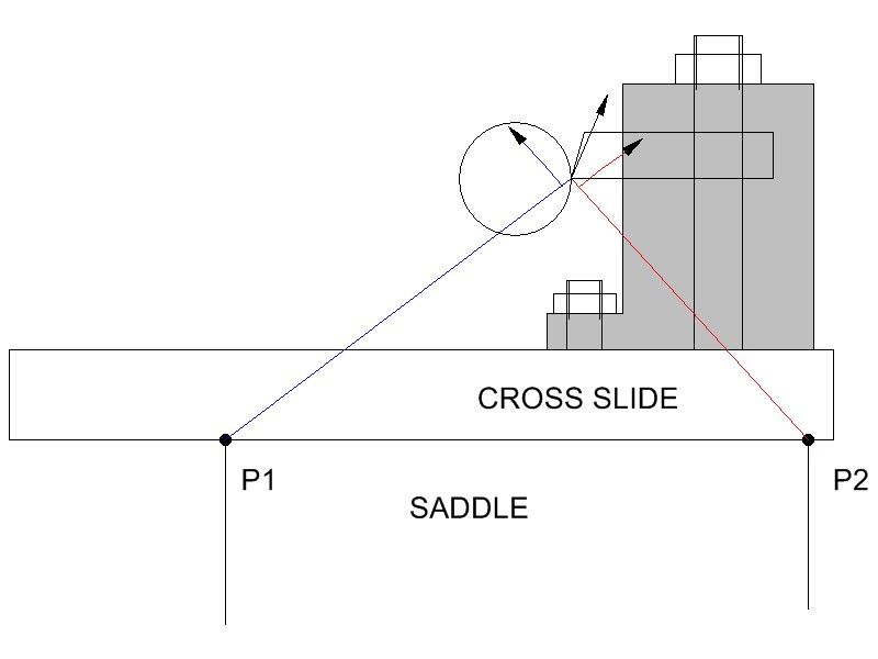
                      Part the Second, and another sketch:

                      rear post.jpg

                      Although the above sketch is not to scale, the relative positions of the cross slide, rear tool post and rear saddle edge are about right when parting with a rear tool post. With a solidly bolted tool post, the post itself isn’t going to pivot about anywhere, the cutting force at the tip must lift the entire tool post and cross slide assembly as one unit. Either lift it vertically, or pivot it about some point… but where?

                      I suggest that the tool tip can only be pivoted about either P2 or P1. It wouldn’t be too difficult to calculate this to determine which one it was in reality, once the weights of the rear tool post, cross slide, top slide and tool post were known, together with the cutting force applied at the tool tip. As far as the cutting force is concerned:

                      About 70 lbs for a 2mm parting blade with an infeed of 0.04mm (0.002” approx) per revolution when parting mild steel.

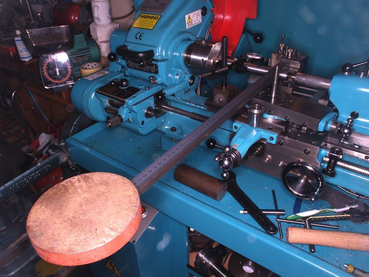
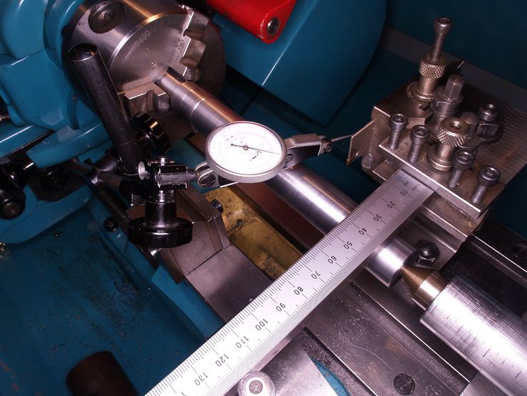
                      Knowing the sort of loads we’re talking about, it’s not too difficult to apply a load and determine how the tip moves. I first did this many winters ago on the S7, and have now repeated it on the Connoisseur, ostensibly for the purpose of taking a photograph of the set up, but really because I couldn’t find my results from years ago and had to re-run the tests. The good news is that they confirmed what I’d found previously. Here’s the set-up:

                      p2093824.jpg

                      p2093823.jpg

                      Something of a jury rig, admittedly, but nevertheless it works well enough for present purposes. Re. the indicator – it’s a Verdict, markings at 0.0005”, which means that tenths can be detected &estimated, but I would not claim to be able to actually measure tenths accurately with it! The results are interesting, units for the deflection readings are 0.0001”.

                      LOAD (lbs)

                      VERTICAL

                      LATERAL

                      C. SLIDE

                      SADDLE

                      72

                      +8

                      +4

                      5

                      0

                      92

                      +16

                      +5

                      7

                      0

                      164

                      +23

                      +8

                      16

                      0

                      Saddle lift – zero, I couldn’t detect any lift at all, so that disposes of the ‘saddle lift’ theory as to why/how a back tool post works well. At least on my lathe, dunno about yours!

                      Vertical lift – the figures are relative to the bed. The vertical lift has two components, i.e. for the 72/92/164lbs. loads total lift was 8/16/23 tenths, of which the cross slide contributed 5/7/16 tenths, the remaining 3/9/7 tenths coming from the Dickson tool block atop the tool post itself, presumably because of loading on the single central hold down bolt.

                      The lateral figures were INWARDS towards the work, not out and away from it. So the pivot point must be at P1, and the tool movement is definitely ‘up & IN’, as per the blue lines on the sketch above, not ‘up & OUT’ (red lines).

                      The results are, of course, for static loading of the tool post. I’ve done some dynamic tests as well, the vertical results were in reasonable agreement with the above, the lateral results showed no movement one way or the other, but I’ll discuss those further when we’ve looked at the front tool post.

                      #179178
                      Russell Eberhardt
                      Participant
                        @russelleberhardt48058

                        Good work Cabeng. It's refreshing to see some good investigative work rather than the constant repetition of opinion we've seen.

                        Now, if that's repeated on the front toolpost I wonder what we'll see.

                        Russell.

                        #179179
                        Michael Gilligan
                        Participant
                          @michaelgilligan61133
                          Posted by Russell Eberhardt on 10/02/2015 09:09:57:

                          Good work Cabeng. It's refreshing to see some good investigative work …

                          .

                          Agreed star

                          MichaelG.

                          .

                          P.S. … I wonder if Neil could get ARNO to do an advisory feature for MEW

                          … Looking at the first few videos here, I think they have it sussed !!

                          #179180
                          blowlamp
                          Participant
                            @blowlamp

                            The inserts designed by the likes of Sandvik & Iscar etc show what's necessary to part off successfully from the front toolpost.

                            Here's the video (yet again)! of me holding a camera in one hand whilst parting off 25mm diameter mild steel with the other on my Mini-Lathe. Surely a Myford can do the same?

                            No coolant, no inverted rear-mounted tool and no slides locked, just properly adjusted gibs – although there is some backlash on the cross slide feed screw.

                            Mini-Lathe parting off Video can be downloaded if playback is choppy or pixelates.

                            Martin.

                            #179182
                            Michael Gilligan
                            Participant
                              @michaelgilligan61133
                              Posted by blowlamp on 10/02/2015 09:40:45:

                              … Here's the video (yet again)! …

                              .

                              Martin,

                              I note that there is a quite substantial 'pip' remaining on the material

                              … Is the tool [deliberately] that far below centre height, or is it fractured, due to the quality of the steel ?

                              MichaelG.

                              Edited By Michael Gilligan on 10/02/2015 09:55:32

                              Edited By Michael Gilligan on 10/02/2015 09:56:45

                              #179186
                              Muzzer
                              Participant
                                @muzzer

                                Cabeng – good to see some actual measurements, although I've yet to see a parting tool that parts off without requiring a fair amount of horizontal force pushing the tool into the work. Your setup simply produces a vertical reaction which is only one of the two main components.

                                If you are going to the bother of setting up and measuring, you might as well make it vaguely representative of the actual situation. Or do you now plan to repeat the test with horizontal-only forces applied?

                                Are you honestly claiming that your saddle doesn't move even 0.0001" vertically under load? Come on, this is now taking on quasi-religious levels of farce!

                                Murray

                                #179192
                                KWIL
                                Participant
                                  @kwil

                                  Martin,

                                  As I said somewhere above, my Myford S7 can, using the Sandvik/Iscar style part from the front at my chosen speeds. If others cannot, then the setup they are using is faulty or else their machine is wanting in one or more respects.

                                  #179193
                                  Martin Kyte
                                  Participant
                                    @martinkyte99762

                                    Eureka . . . that must be it. Paint your lathe bright blue.

                                    :0)

                                    #179194
                                    blowlamp
                                    Participant
                                      @blowlamp
                                      Posted by Michael Gilligan on 10/02/2015 09:54:53:

                                      Posted by blowlamp on 10/02/2015 09:40:45:

                                      … Here's the video (yet again)! …

                                      .

                                      Martin,

                                      I note that there is a quite substantial 'pip' remaining on the material

                                      … Is the tool [deliberately] that far below centre height, or is it fractured, due to the quality of the steel ?

                                      MichaelG.

                                      I estimate the pip is not much more than 1mm across, which I think is a typical result under those circumstances.

                                      From memory, the tool was at centre height and definitely wasn't fractured – the steel was just an offcut of normal quality.

                                      Martin.

                                      #179200
                                      Michael Gilligan
                                      Participant
                                        @michaelgilligan61133
                                        Posted by blowlamp on 10/02/2015 11:09:16:

                                        I estimate the pip is not much more than 1mm across, which I think is a typical result under those circumstances.

                                        From memory, the tool was at centre height and definitely wasn't fractured – the steel was just an offcut of normal quality.

                                        .

                                        Martin,

                                        Thanks, and apologies for the clumsy wording of my question … when I asked if 'it' was fractured, I meant the pip, not the tool.

                                        MichaelG.

                                        .

                                        P.S.  Your result may indeed be 'typical' … that's why I was so impressed by the ARNO videos here

                                        Edited By Michael Gilligan on 10/02/2015 12:10:06

                                        #179202
                                        Anonymous

                                          I think a 'pip' is pretty much inevitable with a straight end to the parting tool, particularly with larger diameter work. I am usually left with a pip on the order of 1-2mm diameter, that looks like it has failed in overload. I normally stop and break off by hand for larger work pieces, as I don't feel inclined to grab rotating work, but nor do I want the work to break off and get dented.

                                          The video links posted by MG were most interesting. When parting steel my swarf comes off pretty much like theirs, lots of small tightly curled balls. Mind you they don't come flying out like theirs. I operate at about the same feedrate, but about a third to a half of the SFM, may be I should try parting at a higher speed?

                                          Andrew

                                          Edited By Andrew Johnston on 10/02/2015 12:38:42

                                          #179203
                                          frank brown
                                          Participant
                                            @frankbrown22225

                                            Cabeng, in the first photograph, you weight loading the tool is pivoting on the saddle, so its not surprising that the saddle is not lifting?

                                            Frank

                                            #179204
                                            JasonB
                                            Moderator
                                              @jasonb

                                              Frank don't they all show the bar resting on the bit of round stock so that is the pivot.

                                              Andrew I wonder if they have some form or air/mist system running thats making teh swarf fly about, if you look at the 4140 steel one at the start of the 125mm piece you can see coolant running down the back of the machine and at the end all the inserts have coolant holes.

                                              Edited By JasonB on 10/02/2015 12:53:39

                                              #179209
                                              Cabeng
                                              Participant
                                                @cabeng

                                                Hello Muzzer & Frank. Clarification…

                                                Muzzer: the results I've shown are for the loads that I applied as given in the table – I didn't detect any saddle lift at those loadings. It does lift if enough load is applied, e.g. by leaning on the lever, when it suddenly 'jumps' up by about 2 tenths. It's an example of one of the non-linearities to which you refered in an earlier posting.

                                                My heaviest chuck on the end of the lever (equivalent to about 240lbs on the toolpost, which is as far as I can go and still be able to determine the loading) doesn't move the saddle when applied as a STATIC load.

                                                240lbs. corresponds to the tip load when feeding a 2mm tool at 0.13mm (0.005&quot per rev.

                                                Shock loading causes the saddle to behave differently, it can be made to lift suddenly by 2 tenths at what I think are lower loadings on the toolpost, but I have no way or applying shock loading in a repeatable manner. Shock loading can however be important during parting, jamming of the chips and all that, I'll be discussing that later… but not in a 'calibrated' manner, I'm afraid.

                                                Re the direction of the applied force – you make a valid point . I know the general direction of the cutting force, but not the specific angle. So I decided to work with the vertical component only, as that was repeatable. Further tests with horizontal force only wouldn't be realistic, as that would merely end up causing lots of backward movement due to backlash in the feedscrew.

                                                Frank: nothing is pivoting on the saddle, the lever pivots on the bar between centres.

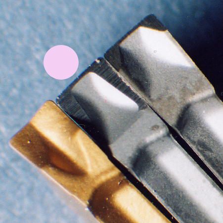
                                                I suppose I should have said something about the machine and parting tips – the lathe has been in service for about 3 years, and is in as-new condition. My S7 is 40 years old, but more about that later. The parting tips are Iscar GFN2/IC20, no other identification on the box re the specific form of the chip control features. It's the one with the dot against it:

                                                parting tips.jpg

                                                #179221
                                                Michael Gilligan
                                                Participant
                                                  @michaelgilligan61133
                                                  Posted by JasonB on 10/02/2015 12:48:51:

                                                  … and at the end all the inserts have coolant holes.

                                                  .

                                                  It's worth having a look at the diagram on p46 of this catalogue extract.

                                                  As I said earlier; I think they have it sussed.

                                                  MichaelG.

                                                  [Just waiting for a decent win on the Premium Bonds.]

                                                  #179223
                                                  JasonB
                                                  Moderator
                                                    @jasonb

                                                    Is the win just to cover the cost of the tooling or will you be buying a ridgid machine to make the most of it, can't see anyone getting those results with the same feed and speed if they stuck one of those cutters into their minilathe or clapped out old flat belt clunker, The cutter only part of the overall solution.

                                                    #179242
                                                    Vic
                                                    Participant
                                                      @vic

                                                      One thing not mentioned so far is the width, or number of "cuts". I was told that no one said you had to just plunge the blade or insert straight into the work piece until the piece is parted. There's nothing stopping you from plunging the tool in a few mm, moving the saddle and then making another cut next to the first widening the cut. Working this way will alleviate many problems. Unthinkable practice for those folks with Harrison's etc but needs must for those of us with small hobby machines.

                                                    Viewing 25 posts - 101 through 125 (of 291 total)
                                                    • Please log in to reply to this topic. Registering is free and easy using the links on the menu at the top of this page.

                                                    Advert

                                                    Latest Replies

                                                    Viewing 25 topics - 1 through 25 (of 25 total)
                                                    Viewing 25 topics - 1 through 25 (of 25 total)

                                                    View full reply list.

                                                    Advert

                                                    Newsletter Sign-up