Posted by derek blake on 13/01/2019 19:50:33:
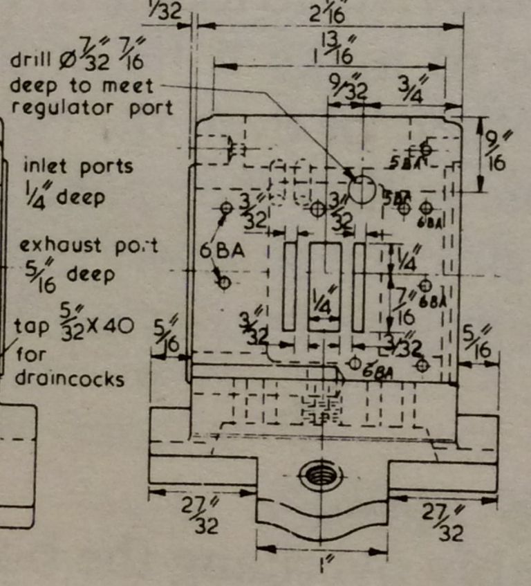
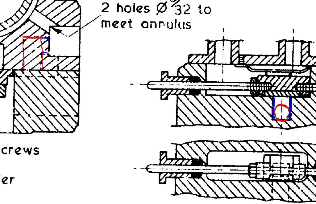
If anyone gets anytime could some direct me to a picture or video that would explain how the steam travels around the Allchin cylinder block and how the holes etc do there job.
I’m keen to learn all I can about what I’m building and how it should work.
Regards Derek
Derek,
I couldn't find easily a video of a traction engine cylinder steam flow or a decent drawing (and don't have Jason's excellent CAD skills to be able to draw one!). Niether do I have direct experience of the Allchin cylinder so have tried to put in words a general description of how steam flows from the boiler to the chimney, hope it makes sense!!
Traction engines, particularly English ones do not normally have a dome to collect 'dry' steam from the boiler like a railway loco. The dome on a loco provides a space where steam collects and is drawn off for use that will hopefully not contain entrained water. So on a traction engine the cylinder casting usually performs this function. The casting is generally hollow around the liner so steam gravitates from the boiler barrel into the the space in the cylinder casting around the cylinder bore, this achieves 2 things, it gives a space seperate from the boiler barrel for the steam to be drawn off for use and because the steam surrounds the cylinder bore (in your case liner) it keeps the bore warm reducing condensation of the steam inside the bore when the engine is running. As you are fitting a liner to create the steam space in the cylinder casting and this space will be directly connected to the boiler and at boiler pressure the seal between the liner and the casting needs to be leak free. Any leak can either get into the bore via the end covers bypassing the slide valve which will lead to reduced or non existent performance or will be blowing to atmosphere! Steam is then taken from the steam space via the regulator to the valve chest via drilled or cast passages. The regulator is arranged so that the high pressure (boiler) side acts on top of the sliding regulator valve, so keeping the regulator on its seating face. It is a good idea to make the regulator port under the valve a pear shape so as the regulator is opened the area of the port exposed to high pressure steam progressively increases, this makes the engine easier to control. The passages for the regulator must not break through into any other passages! Once the steam is in the valve chest it is directed to each end of the cylinder by the valve. The steam ports (outer two ports) and the drillings to the ends of the cylinder again must not break through to any other area or drilling. The exhaust port (wider, centre port) is connected to the steam outlet flange for the blast pipe on the exterior of the cylinder casting again by drillings or cast passages and again these must not break into any other passage or area. So you have four areas that must remain isolated from each other within the cylinder block, the high pressure steam space around the liner, the regulator passages and valve to the steam chest, the steam ports to each end of the cylinder and the exhaust arrangement. You will also likely have cylinder drains which are drilled directly from the external boss where the clave will be fitted to the bottom of the bore and usually a steam take off for the steam blower that will be drilled from a point on the front face of the cylinder 'block' directly into the high pressure steam face surrounding the liner (with your engine it will probably turn 90 degrees down and connect with the space in the saddle.
1000 words when a decent picture would do!
As to piston material, bronze as Jason said should be fine. Remember 'technically' the piston does not run on the liner as it is supported by the rings although in practice that is a moot point. Full size generally have cast iron cylinders and pistons, another example of a material running on itself if you like.
Paul.
derek blake.


