Parallelism of carriage to spindle. Taper.

Advert

Parallelism of carriage to spindle. Taper.

Home Forums Help and Assistance! (Offered or Wanted) Parallelism of carriage to spindle. Taper.

Viewing 13 posts - 26 through 38 (of 38 total)
  • Author
    Posts
  • #626544
    Hopper
    Participant
      @hopper

      The last Optimum lathe I looked at had a 1mm bend in the bed like a banana. Let's hope yours is better than that.(There is a thread on here somewhere about it, started by Brian John, titled something like My New Lathe.)

      Beware of test bars. The hobby grade ones are notoriously poorly made in many cases and run out of true. And in the hands of a beginner, even a good test bar can be set wonky in the headstock taper and give a false reading.

      Your best way is to follow the latest video Huub posted, where you take a test cut along a piece of bar 25mm diameter, sticking out of the chuck about 100mm. Smaller diameter pieces may flex under load and give a false reading.

      The facing test tells you nothing for sure about the headstock spindle alingment. It includes two other variables: the carriage to bed interface and the alignment of the cross slide ways to the carriage. Both these will influence facing cut even if your headstock spindle is aligned. So forget about that test for you current purposes.

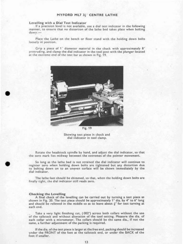
      If your lathe can be bolted to the bench, which I think it can, you can correct small amounts of taper by putting shims under one foot at the tailstock end and tightening down the bolts again. It twists the bed ever so slightly and brings it into alignment. May sound rough, but it is official practice. The Myford ML7 manual, see below, gives the best description of how to do it. The shimming is mentioned at the bottom of the page. Start with maybe 5 thou shim or so.

      (Reproduced here in part for the purpose of education and review, as per fair usage provision of the Copyright Act.)

      myford manual 1.jpg


      NOTE: Do not use the tailstock centre when doing any of these tests. Its alignment is a separate issue, to be done after this first step has been successfully completed.

      Edited By Hopper on 28/12/2022 22:43:49

      Advert
      #626601
      Howard Lewis
      Participant
        @howardlewis46836

        Recently I saw a new small lathe, again not intended to be bolted to a bench, that, when checked, had a visible misalignment of the Tailstock centre to the Headstock one..

        Being a small lathe, and lacking a suitable MT alignment bar, a piece of silver steel was made into one..

        In a 4 jaw chuck on another lathe, the silver steel was held just out of the chuck jaws and clocked until running true to better than 0.0005" (0.012 mm ) before being centre drilled.

        The bar was reversed, end for end, and the process repeated.

        Setting between centres in the new lathe, the Tailstock was found to be 0.022" ( 0.055 mm ) out of line.

        The Tailstock was adjusted (Being a basic small lathe, it had no screws to adjust the body across the bed,, so the Tailstock had to be removed, and the clamp screw eased to allow the upper body to be adjusted, using a G cramp between the upper and lower parts of the Tailstock until acceptable alignment had been achieved when clamped on the bed again.. )

        Once the clamp had been tightened, and the alignment rechecked with the Tailstock firmly clamped to the dovetail bed..

        Happily, the misalignment was now less than 0.0005" (0.012 mm) and considered to be acceptable, otherwise the process would have been repeated..

        Howard

        #626700
        Cedric
        Participant
          @cedricblaver37709

          Hi Huub thank you for the video.

          I dont have a 25mm aluminum bar but used a 22mm steel bar at 100mm distance.

          My cut before measuring was 0.1 mm.

          Chuck dist =21.830mm radius =10.915

          End dist =21.845mm radius =10.923

          Zeroing the dial gauge at the END and rotating the gauge flickers between 0 and 0.01

          Then traming down to the chuck end I get a runout of minus 0.10mm.

          Please see attached photo of a length of 6mm hex bar.

          Please advise as I dont know how to correct this.

          Many thanks.Lathe taper

          #626728
          Hopper
          Participant
            @hopper

            So you are saying your test piece measured 21.83 at one end and 21.845 at the other? That is only .015mm variation. That is half a thou in imperial measure. You probably will not get better than that on a cheap small hobby lathe. Half a thou is pretty good. If you want to make it perfectly parallel, some emery paper on the job at the end of turning will get rid of that half a thou taper.

            Otherwise, the fix, if you want to strive for perfection, is as I told you before, shimming the feet where the lathe is bolted down, as per the Myford instructions I posted. This twisting of the bed by shimming under the mounting bolts is the only way to adjust the headstock spindle alignment for a beginner in a home workshop. There is no other way on your lathe.

            The runout when you rotate the job has nothing to do with alignment. What you are reading there are surface imperfections. Again, .01mm runout as you rotate the job is very good. You will not get it better than that on a small hobby lathe.

            Not sure what you are saying at the end with .10 "runout"? Runout is only when you rotate the job.

            Don't use the tailstock centre for any of these tests as shown in your picture. Alignment of the tailstock is a completely separate issue from either headstock spindle alignment or runout. It is completely independent of spindle alignment. If you are turning a taper with the tailstock centre in place, it means the tailstock centre needs adjusting sideways by half the amount of that taper. Usaually there is some facility in the base of the tailstock to do this. Some kind of adjusting bolts and clamping bolts that allow the base of the tailstock to remain on the bed and the top half of the tailstock to move a tiny bit sideways.

            Looking at pictures of your model lathe on the net, it appears to have a tailstock aligment adjusting screw of some sort on the base of the tailstock towards the right hand end of the base. You can see the square dovetail on which the top half of the tailstock can move sideways. There will be some kind of locking or clamping bolts that need loosening before you adjust the alignment screw.

            Edited By Hopper on 30/12/2022 11:20:16

            #626764
            Huub
            Participant
              @huub
              Posted by Cedric Blaver on 30/12/2022 09:10:06:

              Chuck dist =21.830mm radius =10.915

              End dist =21.845mm radius =10.923

              Zeroing the dial gauge at the END and rotating the gauge flickers between 0 and 0.01

              Then traming down to the chuck end I get a runout of minus 0.10mm.

              Please see attached photo of a length of 6mm hex bar.

              Lathe taper

              I assume you did not use the tail stock to turn the 22 mm test bar because that would make the results dependent of the alignment of the tail stock

              Correct me if I am wrong your measurements Rotation of the headstock as seen from above:

              • You did not use the tail stock during turning
              • 0.03 mm/100 mm horizontal misalignment of the head stock + carriage using the facing method, rotation CCW
              • 0.10 mm/100 mm horizontal misalignment of the head stock using the turning method, rotation CCW
              • You measured a 0.01 mm runout on the turned diameter measured at 100 mm distance of the chuck.

              If have checked an online Optimum TU2406 manual but did not find bolts to adjust the headstock. This means that you have to grind/file/sand/scrape the bottom of the headstock to make adjustments. I used a 20 mm worn diamond dremel disk to adjust the headstock of my small lathe. Adjusting takes about half a day. To do that, you have to dismantle the lathe so you can reach the bottom of the headstock. That takes a bout a day.

              In short the procedure I followed using the diamond disk and grounded manually:

              • Turned the alignment bar and measured the alignment Horizontal and Vertical. You can't remove the bar and chuck during the whole procedure
              • Dismantled the lathe
              • Removed the headstock, cleaned all surfaces, bolted it on again and measured the alignment
              • Removed the headstock and grounded the flat surface of the headstock until all 4 corners of the headstock rest on the lathe bed.
              • Bolted on the headstock and measured the alignment Horizontal and Vertical.
              • Removed the headstock and grounded the 90° and flat surface of the headstock until it was aligned Horizontal and Vertical. Made measurements without bolting the headstock to the lathe bed.
              • Finally bolted the headstock to the lathe bed and did the final measurements.

              If you grind the flat surface and both the angled surfaces on the front side, the headstock will bend over and you can adjust a vertical misalignment.
              If you grind the front angled surface at the backside and the back angled surface at the frontside, the headstock will turn CW and your misalignment will reduce.

              You grind away the top spots. To find a top spot, you mark the bed with a black pentel pen, place the headstock on the bed and move it from left to right and back, 2 mm, a couple of times. The black ink on the headstock indicates the top spot. You will find "scratches" on the lathe bed at the same place.

              I used the "same procedure" to correct the misalignment of the tail stock from my bigger lathe.

              You can measure the vertical alignment of the headstock by placing the dial on top of the headstock.

              Before you do this, you better consult the seller of the machine.

              In the netherlands, Optimum has a far better reputation than HBM (my lathe brand).

              #626766
              Stuart Smith 5
              Participant
                @stuartsmith5

                Cedric

                You asked if there is anyone near Andover who could help. What about contacting the local model engineering club?

                I looked online and found Andover and District Model Engineering Society. They have a website and Facebook page.

                **LINK**

                Stuart

                #626769
                SillyOldDuffer
                Moderator
                  @sillyoldduffer

                  Further to Hopper's comments, it's wise for new owners to approach these issues with caution.

                  • Using the wrong terminology is confusing, because 'run-out' refers to a particulr tye of error, which is probably why the vendor replaced the chuck jaws.
                  • Taking measurements and diagnosing what they mean is much harder to do correctly than it might seem. Measurements have to be taken accurately to better than about 0.02mm, and there are many, many ways of getting it wrong. The instruments may not be up to it, and the operator has to use them properly, which requires skill and practice.

                  Jumping in at the deep end with tricky measurements, it's all too easy to convince oneself that something is wrong with the lathe, when the cause is something else, like a misunderstanding or poor technique. For that reason I suggest learning to use the lathe. Practice on a free-cutting Aluminium. If the lathe does what's needed of it, the suspicious measurements are irrelevant. However, if the lathe persistently misbehaves whatever the operator does, then it's time to pin down the cause. This can be done with sequences of test cuts, as described above, but the job has to be approached methodically. If the cause is a twisted bed, simply fixed by shimming the feet, it's a bad mistake to take the headstock off and attack the bed with a Dremel!

                  Fingers crossed, it isn't a fundamental problem with the lathe. It is possible; duds do occasionally reach customers and have to be sent back. But it's more usual to find small faults that can be fixed at home with a bit of fettling.

                  Dave

                  #626773
                  Huub
                  Participant
                    @huub
                    Posted by SillyOldDuffer on 30/12/2022 14:02:40:

                    If the cause is a twisted bed, simply fixed by shimming the feet, it's a bad mistake to take the headstock off and attack the bed with a Dremel!

                    By no means I mean you should use a Dremel. If mean use a Dremel diamond disk and do it by hand. Keep the Dremel in the Box.

                    #626835
                    Howard Lewis
                    Participant
                      @howardlewis46836

                      If there is a problem with Headstock alignment, using the Tailstock might hide or worsen nthe apparent problem, as will a chuck.

                      You have to make some assumptions. Otherwise you are going tom have to completely strip the lathe to check EVERY dimension. WHERE do you stop?

                      One is that the Morse Taper in the spindle is concentric with the spindle in every plane.

                      If that assumption is true, the Alignment Bar (ASSUMING that it is accurate and that the Morse taper and parallel section are concentric, and true to size all the way along ) can be used to check Headstock alignment relative to the bed, in both planes.

                      My 3 MT Alignment bar was checked in the Standards Room and was within 0.0005" (0.0127 mm ) over a 18" (450 mm ) length. Calibration Room personnel considered that that would be sufficiently precise for hobby work!

                      Having made these assumptions, if you can clock the unsupported Alignment bar to within 0.0005" (0.0127mm )

                      I would be content. You have a hobby lathe, not a Toolroom machine.

                      (There is a great price differential between the two to accommodate the differing levels of of precision. )

                      If your 3 jaw chuck can hold round material to better than 0.005" (0..127 mm) eccentricity I would be satified.

                      If you have to have two or more diameters absolutely concentric, turn them without disturbing the work in the chuck.

                      Don't get waylaid by delusions of accuracy, otherwise you start checking the accuracy of the threads on your micrometer! To do that you need a temperature and humidity controlled environment, after the specimen has soaked for at least 24 hours, where they can check accuracy of slip gauges to millionths of an inch!.

                      Howard

                      #626838
                      Hopper
                      Participant
                        @hopper

                        Before any further suggestions, I think the OP needs to clarify just how much taper over 100mm he is getting when turning a test bar with no tailstock centre used.

                        I am understanding his last post to say it is 0.015mm. Huub is understanding it to be 0.1mm. Two very different things with two very different answers.

                        Cedric Blaver, please clarify.


                        Edited By Hopper on 31/12/2022 02:20:38

                        #626864
                        Howard Lewis
                        Participant
                          @howardlewis46836

                          Cedric,

                          It may be that your lathe bed is twisted.

                          I'll send you a PM

                          Look for the flashing black envelope at the top of the screen.

                          Howard

                          #626891
                          Cedric
                          Participant
                            @cedricblaver37709

                            Hello everyone. A happy new year for tomorrow.

                            Thank you very much for all your help and input.

                            I re-did the test again today, starting fresh no tailstock used.

                            I took the 22mm steel bar and made 2x cuts of 0.10mm.

                            Then 2x cuts of 0.01mm.

                            Then using the same setting as the last made a final pass, just to remove any little bumps.

                            Chuck dia 21.315mm

                            End dia 21.300mm

                            Chuck dist 0.005

                            End dist 0.005

                            No difference between the two ends.

                            I fail to understand what i was doing wrong in the past.

                            I then took the 6mm hex bar and machined a 20mm length without the tailstock doing small cuts of 0.01mm. No visable taper was noticed.

                            Ive had a cheap mini lathe for 6 years and never had the taper issues that Ive had with the new lathe.

                            As someone posted maybe I need to learn the new lathe.

                            Once again thank you all very much for your help and input.

                            Cedric.

                            #626893
                            Hopper
                            Participant
                              @hopper

                              Happy new year to you too.

                              Well, the two diameters of 21.315 and 21.300 is close enough for hobby work so no problem there.

                              I do not understand what you are meaning by "Chuck Dist" and "End Dist". Can you clarify please.

                            Viewing 13 posts - 26 through 38 (of 38 total)
                            • Please log in to reply to this topic. Registering is free and easy using the links on the menu at the top of this page.

                            Advert

                            Latest Replies

                            Viewing 25 topics - 1 through 25 (of 25 total)
                            Viewing 25 topics - 1 through 25 (of 25 total)

                            View full reply list.

                            Advert

                            Newsletter Sign-up