Oscilloscope kits – any recommendations?

Advert

Oscilloscope kits – any recommendations?

Home Forums Electronics in the Workshop Oscilloscope kits – any recommendations?

Viewing 25 posts - 1 through 25 (of 35 total)
  • Author
    Posts
  • #470478
    Robin Graham
    Participant
      @robingraham42208

      OK, a bit of a 'what lathe should I buy' question I know. It depends on what you want to do…

      The reason this has cropped up that I would like to be able to look at the data output from various capacitive DRO scales I have. From what I've been able to discover these are likely to have a 10kHz clock – so I guess I don't need anything too fancy.

      I'm pretty much at sea here, so any practical advice would be welcome.

      Robin

      Advert
      #32091
      Robin Graham
      Participant
        @robingraham42208
        #470496
        Mike Poole
        Participant
          @mikepoole82104

          Pico technology make useful interface units for laptops or PCs if that would suit your purpose, no doubt there are Chinese versions at keen prices but I have not used one. My Tektronix is still going well but the price of probes is frightening.

          Mike

          #470499
          harold
          Participant
            @harold

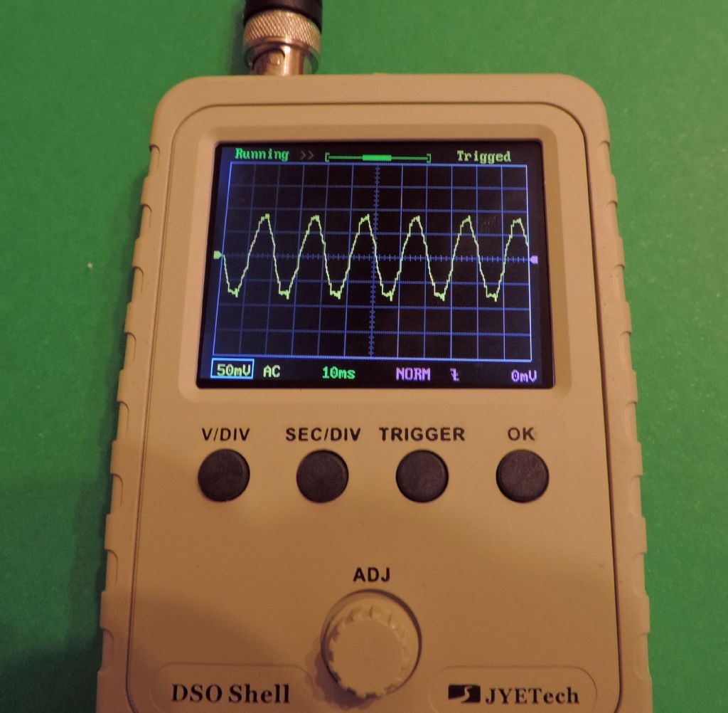
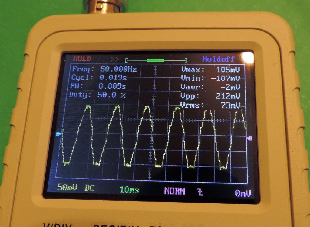
            DSO shell from JYE tech. It's saved me so much hasssle setting up CNC and doing amp repairs, because it's small, compact and 'good enough'.

            #470501
            Maurice Taylor
            Participant
              @mauricetaylor82093

              I would also suggest a Picoscope,they start at £99 ,you can download the software from their website free , and play with it in demo mode .I use one myself.

              #470502
              duncan webster 1
              Participant
                @duncanwebster1

                if your computer has a parallel port I've got an old PicoScope thing you can have, but it will be a pretty ancient computer!

                #470504
                not done it yet
                Participant
                  @notdoneityet

                  I would be surprised if there was not an app, of some description, for a smartphone. Might be good enough for your application?

                  #470505
                  Stuart Smith 5
                  Participant
                    @stuartsmith5

                    It depends how much you want to spend and what you want to get from it. As has been said, Pico make a range.

                    I have a PoScope basic usb oscilloscope which is a few years old now. The later version to mine is sold as the PoScope Mega1 bundle with usb scope and leads **LINK** . It is 109 euro from the makers. Robot shop.com advertise it at £91.42 but awaiting stock.

                    I also have a Rigol DS1054z but at £350 it is probably more than you want to spend.

                    A cheap option if you just want to analyse digital 0 to 5 volt signals is a diy usb scope using an Arduino. This is a link to a site showing how to use an Arduino uno. **LINK** . I have made one using an Arduino nano which is a bit cheaper than a uno. The last one I bought was only about £5 from hobbycomponents.com inc p&p

                    Stuart

                    #470507
                    Stuart Smith 5
                    Participant
                      @stuartsmith5

                      Re my previous post

                      The instructions for programming the Arduino and the software to run on your pc are here **LINK**

                      This is a screenshot of the sort of display you get

                      48cb2717-ee5a-4944-98e4-0393ff9e8562.jpeg

                      #470509
                      Stuart Smith 5
                      Participant
                        @stuartsmith5

                        Velleman also make a Range of kits or complete scopes. They do a kit with a black and white lcd screen for £49.

                        I have a self contained Velleman scope which is handy as it is battery powered but it has quite a small screen with poor contrast, so I only use it for portable uses.

                        Stuart

                        #470559
                        mike barrett
                        Participant
                          @mikebarrett73459

                          Picoscope are very good with excellent software and support.

                          Be careful if you buy an old one off Ebay as some of the drivers (particularly for the data loggers) are no longer supported on Win 10. Just check on there web site before buying! Guess how I know… ;(

                          Mike

                          #470575
                          Russell Eberhardt
                          Participant
                            @russelleberhardt48058

                            Have a look at BitScope. It is both a dual channel analogue scope and a simple logic analyser for use with a computer via USB.

                            **LINK**

                            Russell

                            #470585
                            Oven Man
                            Participant
                              @ovenman
                              Posted by harold on 09/05/2020 23:15:49:

                              DSO shell from JYE tech. It's saved me so much hasssle setting up CNC and doing amp repairs, because it's small, compact and 'good enough'.

                              I got one of these, or a clone, ready built for just over a tenner. It has only got 200kHz bandwidth but for working with audio or stepper motor drives its is perfectly adequate. If you only want it for a one off job then it's a cheap almost disposable route. For the real stuff my old Telequipment valve scope still does sirling service.

                              Peter

                              #470591
                              Joseph Noci 1
                              Participant
                                @josephnoci1

                                Robin,

                                Your post implies a 'kit' – ie, are you looking to build up a parts kits or do you mean 'kit' as in a working bit of kit..??

                                The picoscope type units are good, some even very capable and overkill for most home applications. Once you have an oscilloscope you begin to easily reach for it to measure things -car servicing, home electrics, lathe/mill motor controls, etc, etc, and you learn as you go. A basic scope-in-the-hand soon become like a multimeter.

                                However, for irregular, basic use, that's where I feel the Picoscope type units fall down. You end up NOT using it for quick checks, because you have to not only get it and its probes out of the cupboard, but have to get the computer up, and if its a desktop you have to bring the problem to the computer, etc…

                                Something you can treat like a mulitimeter is just so much more convenient for casual use!

                                If you only want to look at low speed signals – sub200KHz, the one Harold mentions is great – works well, but single channel. I would suggest is to try go for a dual channel scope – your DRO outputs will be two channels and its useful to see the phase relationships.

                                If you take a look at some of the oriental offerings, eg on Banggood, search Oscilloscopes, the one Harold mentions goes for $17.00 as a kit, $21.00 assembled in a box..A 2 channel version is around $65.00 complete with probes, assembled, etc ( jyetech15801 – also 200KHz)

                                A very nice one is the JDS6052s – 2 channel at 25MHz each or 1 @ 50MHz – plus a 1Hz – 5MHz signal generator for $100.00 – I have a half dozen of these out in field service vehicles – used by Wildlife rangers to help me debug RF logging towers in remote locations! The units survive the bundu well.

                                Joe

                                #470597
                                SillyOldDuffer
                                Moderator
                                  @sillyoldduffer

                                  How brave are you? There are several free PC software oscilloscopes available. The main problem is input volts are connected directly to your computer with no protection against mistakes. The user has to make certain he won't fry his expensive sound-card, either by measuring the input with a multi-meter first, and/or by providing a resistive divider to control maximum levels. Easy enough to condition a 0 to 5V TTL logic signal, much trickier when negative or higher voltages are involved. Simple software oscilloscopes don't measure amplitude accurately, may not matter – the time and shape of the waveform are often more interesting.

                                  Devices like the Picoscope provide all the necessary protection plus accuracy and lots of extra functionality. Easy to use, but prices start at about £100 for basic 10MHz dual-channel capability. 10MHz is more than adequate for checking a DRO. (Although most ordinary work can be done with 5MHz or less, 20MHz is nice.)

                                  Under £100, there are several useful kits available. They either display on a computer like a Picoscope, or come with a small screen. The latter type are more limited, but still useful for basic electronic work. Check the bandwidth: 200kHz is common, but some only do 20kHz, which isn't much use. Buying a kit saves money because considerably less tax is levied on kits. Aimed at chaps who own a soldering iron, but very often the 'kit' is 99% finished. Or it might be a box of parts, because lots of people want that. It will probably need some soldering.

                                  Also under £100, multimeters with a tiny built-in oscilloscope; as far as I know these are all very limited. (Not very capable electrically, and they have tiny hard to see screens. )

                                  More than £250 gets into out-of-the-box Digital Storage Oscilloscope territory, mine does 100MHz. Over the last 10 years or so they've revolutionised inexpensive oscilloscopes – very functional, high-performance, and affordable. When I was a lad oscilloscope performance this good cost as much as a new family car, or more! Very easy to use, but a lot of money just to explore a DRO scale. Well worth the money if electronics are more than a passing interest.

                                  Dave

                                  #470601
                                  Bazyle
                                  Participant
                                    @bazyle

                                    SOD mentions accuracy of amplitude but what about timebase.. Has anyone for example tried some sort of detector on their lathe spindle and then looked at the speed variations – if variations are seen are they the lathe or the scope?

                                    If not leading the thread off topic too far is there a low frequency spectrum analyser? I'm thinking in terms of analysing lathe vibrations so low frequency like audio range.

                                    Forty years ago I built the Watford Electronics 'scope kit based on the 3 inch wartime radar tube 3BP1.

                                    #470603
                                    Robert Atkinson 2
                                    Participant
                                      @robertatkinson2

                                      Plus 1 for Picoscope. Been a happy customer personally and for work for over twenty years. For beginers 'scopes are a bit like welders, it's easier to get good results with a better model. There are two problems with the low end models, low bandwith (maximum frequency you can measure) and limited input voltage, often only 5V maximum. The latter can be made worse by non-standard input impedance which means standard 10:1 probes can't be used. A 200kHz 5V unit is just about good enough for looking at a caliper based DRO. A mid level range between the low end stuff and Pico Technology is sold by Hantek but I've never used one. If you have space a "proper" conventional oscilloscope could be a good option. Hameg, Philips and Farnell are brands to look at as well as the obvious Tektronix and HP.
                                      Ebay may not be the best place to buy a 'scope. A bit of a "sleeper" is the HP 54600A/B range. These are digital 'scopes with a CRT display. The are more compact than a conventional CRT 'scope because the TV type CRT is much shorter. You can get a 54600B 2 channel 100MHz (2MHz single shot) model from Stuart of Reading for £75 (plus VAT). The 54600 cost over £2000 new in 1993. Stuarts are a well respected dealer. The higher specification 546xx models especially the "MegaZoom" models are even better. The 546xx gets a lot of bad press on the web mostly from Tektronix snobs. My 54645D is my favorite non PC based 'scope even above much more modern and expenive ones at work.The user interface is excellent. For PC use I have 3 Picosopes.

                                      Robert G8RPI.

                                      #470604
                                      Anonymous
                                        Posted by Bazyle on 10/05/2020 12:10:47:

                                        If not leading the thread off topic too far is there a low frequency spectrum analyser? I'm thinking in terms of analysing lathe vibrations so low frequency like audio range.

                                        Don't know if one is available for the amateur, but they exist for the professional. They're called signal or waveform analysers. They're part spectrum analyser, part oscilloscope and part network analyser. Generally they will perform Fourier transforms, measure the response of a filter or amplifier and allow waveforms to be shown over time. The latter is often called a waterfall display. Successive scans in time are displayed offset in two dimensions so you get a 'waterfall' showing how the signal changes over time.

                                        In the past I've used them for measuring filters with arbitrary pole/zero locations, for assessing the performance of active noise systems (*) and the performance of a 30Hz radio.

                                        Andrew

                                        (*) Being stuck 150ft up on an electro-precipitation stack at a cement works, at midnight, trying to work out why an active noise controller isn't working doesn't rate highly in my list of fun things to do.

                                        #470606
                                        Michael Gilligan
                                        Participant
                                          @michaelgilligan61133
                                          Posted by Bazyle on 10/05/2020 12:10:47:

                                          .

                                          If not leading the thread off topic too far is there a low frequency spectrum analyser? I'm thinking in terms of analysing lathe vibrations so low frequency like audio range.

                                          .

                                          There are several candidates on the iOS AppStore … but this was my first choice, and it does everything one could reasonably expect : **LINK**

                                          http://www.dld-llc.com/Diffraction_Limited_Design_LLC/Vibration.html

                                          MichaelG.

                                          #470615
                                          Neil Wyatt
                                          Moderator
                                            @neilwyatt

                                            As you just want an inexpensive tool to get a job done rather than something capable of handling limitless possibilities Google KKmoon 2.4" digital oscilloscope

                                            (Edit this is the same thing as the JYE Tech scope)

                                            For £20-30 you will have a pocket scope more than capable (200kHz max frequency) of doing what you need.

                                            I'd add that having used scopes of all sorts these are actually very good within their limitations -its fantastic being able to take a scope to the job rather than the other way around. I've used it with a microphone to compare the frequency responses of loudspeakers. I've 3D printed a cradle for it that takes an old phone battery, charger and voltage booster.

                                            scope 1.jpg

                                            scope 2.jpg

                                            I would suggest ordering a set of X10 probes at the same time. Cheap ones will be fine.

                                            Neil

                                            Edited By Neil Wyatt on 10/05/2020 13:48:51

                                            #470627
                                            Les Jones 1
                                            Participant
                                              @lesjones1

                                              Hi Robin,
                                              This information on scale protocols may help you.

                                              ————————————————————————-
                                              Scale protocol information.

                                              2 * 24 bit scales

                                              Data is sent as two groups of 24 bits.
                                              Each group is a 24 bit binary number. The first bit received is the least significant bit.

                                              Bits
                                              are transferred LSB first! Also, data is 2's complement. (ie inverted Data signal at 0 volts = 1 at +1.5 volts = 0)

                                              Static state of clock signal between frames Low
                                              Time between start of frames 330 mS Normal mode 25 mS fast mode
                                              Length of data frame 860 uS
                                              Length of clock cycle about 14 uS
                                              Time clock pulse is negative about 7 uS
                                              Time clock pulse is positive about 7 uS
                                              Initial high at start of frame about 52 uS
                                              High in the middle of frame about 110 uS
                                              High at end of frame about 80 uS

                                              Clock in the data on the negative going edge.

                                              The first group is the absolute position. It has some arbitary value at power on.
                                              The second group is the relative position. This will be zero after the zero button is pressed.
                                              Its value will be the difference between the absolute value when the zero button was pressed and
                                              and the current absolute value.

                                              48 bits in a frame of data

                                              CPI 20480

                                              ————————————————————————-

                                              HF (Bin 6 scales)
                                              LSB Sent first.

                                              Static state of clock line between frames High
                                              Time between start of frames 180 mS (I measured about 210 mS)
                                              (I have seen 133 mS quoted elsewhare.)
                                              Time of gap between nibbles about 700 uS
                                              Length of data frame 13 mS
                                              Interrecord gap 167 mS
                                              Time between start of nibbles within frame 2.2 mS
                                              Clock cycle time about 450 uS
                                              Time clock pulse is negative about 320 us (Logic 1)
                                              Time clock pulse is positive about 130 us (Logic 0)

                                              Clock in the data on the positive going edge.

                                              The data output is the number displayed on the LCD display.
                                              Set scales to metric mode and this will corespond to 2540 CPI ( 0.01 mm) per count)

                                              24 bits of data (6 bytes) Least significant comes out first. Bits 0 to 19 is the reading in binary (The same value as that displayed in decimal on the scale display. Bit 20 is the sign bit set for negative Bits 0 to 19 are always a positive number.
                                              Bit 23 is set when in inch mode.

                                              24 bits in a frame of data

                                              CPI 2540 (Metric) (2000 in imperial mode.)

                                              This is only half of it as it would not let me include it all in 1 post. The rest is in my next post.

                                              Les.

                                              #470629
                                              Les Jones 1
                                              Participant
                                                @lesjones1

                                                7 BCD Scales
                                                LSB Sent first.

                                                Static state of clock line between frames Low
                                                Time between start of frames 330 mS
                                                Length of data frame 820 uS
                                                Interrecord gap 329 mS
                                                Time between stat of nibbles within frame 110 uS
                                                Length of clock cycle about 12 uS
                                                Time clock pulse is negative about 6 uS
                                                Time clock pulse is positive about 6 uS
                                                High level at start of frame about 55 uS
                                                High level between nibbles about 60 uS
                                                High level at end of frame about 60 uS

                                                Clock in the data on the negative going edge.

                                                Top nibble
                                                Bit 0: sign. L = +, H = –
                                                Bit 1: in inch-mode H means +0,0005 inch, unused in mm-mode.
                                                Bit 2: unit: mm/inch. H= mm; L= inch
                                                Bit 3: unknown.

                                                28 bits in a frame of data

                                                CPI 2540 (Metric)
                                                ————————————————————————-
                                                iGaging (21 bit)

                                                LSB sent first
                                                The 21 bits are all used as a 21 bit binary number. (No bits used as flags.)

                                                Static state of clock line between frames Low
                                                Static state of data line between frames
                                                Time between start of frames 7 mS
                                                Length of data frame about 2.33 ms
                                                Interrecord gap about 4.67 mS
                                                Time between clock pulses about 111 us (Clock cycle time.)
                                                Time clock pulse is negative about 89 uS
                                                Time clock pulse is positive about 22 uS
                                                High level at start of frame about uS

                                                Clock in the data on the negative going edge.

                                                CPI 2560

                                                21 bits in a frame of data

                                                ————————————————————————-
                                                I collected this information when I was writing code to read all the above types using an Atmel Attiny4314.

                                                Les.

                                                #470634
                                                SillyOldDuffer
                                                Moderator
                                                  @sillyoldduffer
                                                  Posted by Bazyle on 10/05/2020 12:10:47:

                                                  SOD mentions accuracy of amplitude but what about timebase.. Has anyone for example tried some sort of detector on their lathe spindle and then looked at the speed variations – if variations are seen are they the lathe or the scope?

                                                  If not leading the thread off topic too far is there a low frequency spectrum analyser? I'm thinking in terms of analysing lathe vibrations so low frequency like audio range.

                                                  Timebase should be good because the scope software uses the sound-card which has an accurate clock.

                                                  I've had a half-hearted go at measuring lathe vibration and a slightly more serious attempt at detecting track vibration from Dynamometer Car data. Duncan Webster's been experimenting with a dynamometer car for measuring steam loco performance. He measures and logs rpm and drawbar pull from which engine power and other data can be derived in the time domain. I was interested in analysing the same data in the frequency domain to see if spring in the load cell coupling was a problem because Duncan suspects this might cause errors, and – my mad idea – to see if vibration caused by track defects could be detected as a maintenance aid. Unfortunately load data is measured once per revolution, which doesn't translate straightforwardly into frequency because loco speed varies.

                                                  Underlying problem with both lathe and dynamometer – my maths! I got as far as understanding the dynamometer data needs to be munged into regular frequency form before applying an FFT, but don't quite understand how to do it. Nor do I know how to apply FFT appropriately either! I got as far as deciding to go back to lathe vibration because the data comes off in frequency form and then stalled.

                                                  I'm using Python and SciPy to crunch the numbers, with this tutorial as FFT starting point.

                                                  Got interested in vibration ages ago after reading it was the first test applied to a newly installed industrial lathe. Said to be vital to finish and done before checking for run-out and parallelism etc. The tool used before electronics doesn't look difficult to make: About 12 pendula are suspended on piano wire from a gantry mounted on a stiff plate about 18" long. The pendula are each tuned to a different period. The gantry is plonked on the ways and the machine taken through it's speed range: when the machine vibrates, one or more pendula swing in sympathy and indicate the period. The hard part is working out cause from the observed frequency and the rpm, and how to dampen out any resonances.

                                                  Don't know how common vibration is in home workshops. My WM280 lathe had a couple of resonances, much reduced by putting roofing felt under the stand as a damper. Before installing the damper I just avoided the guilty speeds, about 800 and 1250rpm. Like as not root cause was failing to bolt the stand down because I didn't want to puncture my garage floor's DPM.

                                                  Dave

                                                  #470663
                                                  Enough!
                                                  Participant
                                                    @enough

                                                    Just saw this fwiw.

                                                    #470664
                                                    Anonymous
                                                      Posted by SillyOldDuffer on 10/05/2020 14:38:

                                                      ……….back to lathe vibration because the data comes off in frequency form and then stalled.

                                                      I'm using Python and SciPy to crunch the numbers, with this tutorial as FFT starting point.

                                                      I'm not surprised; it's hardly a tutorial. It's incorrect to state that the Fourier transform of a real function is even. The real part is even, but the imaginary part is odd. Of course the magnitude will be even.

                                                      Strange that they don't mention the number of samples per transform. While the number of samples can be any highly composite number, the original FFT works best when N is a power of 2. To the extent that if the data set isn't a power of 2 long, zero value samples are added to pad out the data sequence.

                                                      Andrew

                                                    Viewing 25 posts - 1 through 25 (of 35 total)
                                                    • Please log in to reply to this topic. Registering is free and easy using the links on the menu at the top of this page.

                                                    Advert

                                                    Latest Replies

                                                    Viewing 25 topics - 1 through 25 (of 25 total)
                                                    Viewing 25 topics - 1 through 25 (of 25 total)

                                                    View full reply list.

                                                    Advert

                                                    Newsletter Sign-up