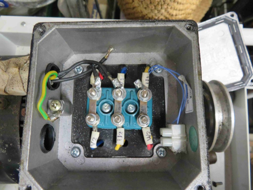
Bill
Sounds like you are sorted then. Might help anyone coming across this thread in future to note that the Digital Operator Frequency Setting Potentiometer is the build in control connected to he knob on the box. The pendant connection is over on the other side indicated by the Frequency Ref curly bracket. Basically Frequency is VFD maker speak for speed.
Its most likely that the centre terminal of your speed control potentiometer goes to the wiper. If so the red wire will go to connector FR. Blue wire to FC and White wire to FS is probably right but if the knob turns the wrong way to speed up or slow down reverse them. May be best to start off with the potentiometer in the middle so as not to get a jump to flat out if the potentiometer connections are the wrong way round and what you think is dead slow setting is actually warp speed.
The turquoise coloured (on my display anyway) wire should go to terminal SC with the black and yellow wires going to S1 and S2 as appropriate to get things turning the right way.
As John says the indentification labels on the terminals are usually small and hard to read. They are often a bit offset from the terminal itself and frequently upside down if the box is mounted on the wall or a machine. Which makes it very easy to connect to the terminal next door to the one you think you are connecting to. Been there, dunnit, caught the error under the "have a coffee then go back and check system". Another place where big printout of the picture with scribble room helps as you can more easily physically count from one end to confirm where the terminal is.
Clive.
Edited By Clive Foster on 11/10/2016 19:08:06
 Neil Wyatt.

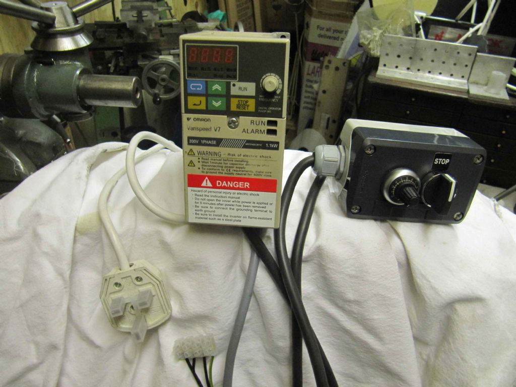
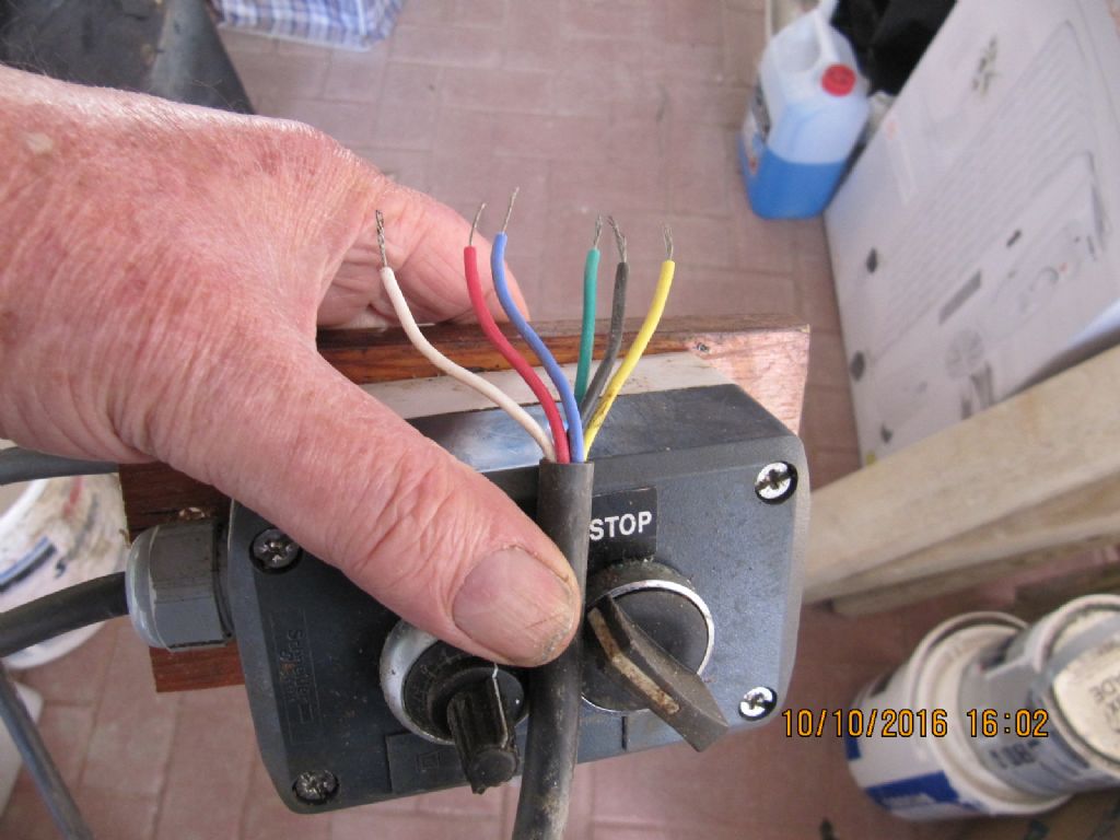
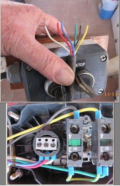
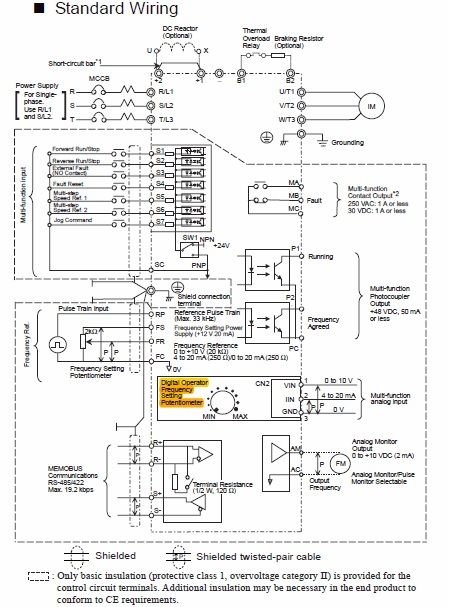
 all marked up as Clive has said, they tiny and not easily read Fs, Fc and Fr. If there isn't wires in those position, then put three wires into those terminals Write down which colours you use.The other ends of those same coloured wire connect the speed control potentiometer get the colour RIGHT. Next locate in the inverter terminals Sc, S1 and S2 and as before connect the remaining three wires into those same three terminals. Finally connect the same three wires into the correct terminals in the forward and reverse switch. Look out for a PM. John