Omron Varispeed V7 – external potentiometer HELP

Advert

Omron Varispeed V7 – external potentiometer HELP

Home Forums Electronics in the Workshop Omron Varispeed V7 – external potentiometer HELP

Viewing 14 posts - 1 through 14 (of 14 total)
  • Author
    Posts
  • #441458
    Peter Graversen
    Participant
      @petergraversen11111

      Hello.

      I bought a second hand Omron Varidrive V7 frequency drive, and wanted to hook up an external potentiometer.

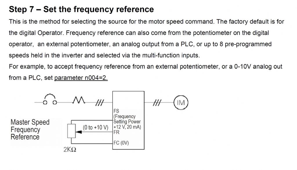
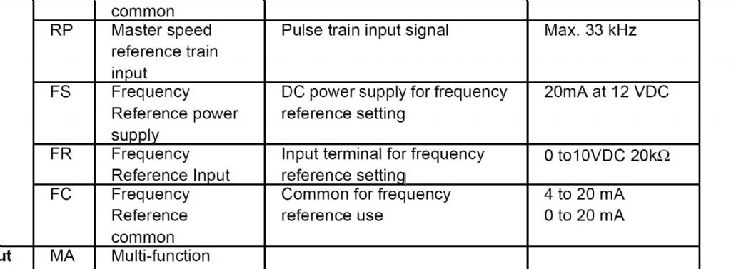
      The online manual is very technical, and not written in a very accessible language, but i have found out that i have to connect the pot to three terminals. FP (frequency reference power supply- 12v 20ma), FR (frequency reference input 0-10v 20ohm impedance) and FC (0v common).

      Since i'm out of my element, i'm bit confused that the FP terminal supplies 12v, but the FR terminal uses 0 to 10v as reference voltage to regulate the frequency.

      They call for a 2K-ohm pot at 1/4w minimum as the analog regulator, so should i put a 500 ohm resistor in series with the pot, at the 12v side, to limit the voltage to 10v? (i don't even know if my maths is right, or really what i'm talking about )
      The diagrams don't show this – only the 2K pot, but the descriptions are very vague, so supposedly this is something i should know in advance, but i don't .

      On many of their other drives the reference power supply is 10v, but not on the V7 series.

      I'm not good at this, and all i want to do is have a knob that can regulate the speed of my machine, without having to get a degree in electrical engineering .

      Advert
      #32051
      Peter Graversen
      Participant
        @petergraversen11111
        #441464
        David Jupp
        Participant
          @davidjupp51506

          Diagram at bottom of page 65 of the manual shows how to wire it.

          #441466
          SillyOldDuffer
          Moderator
            @sillyoldduffer

            In practice the difference between 12 and 10V probably doesn't matter, but I'd lose the excess volts with a resistor exactly as you propose. Why risk blowing the drive up for the few pence it costs to fit a resistor?

            There's an online calculator here. It suggests a standard value 390Ω resistor in series with a 2000Ω pot. 500Ω would be OK too – pots are often only ±20% accurate.

            But I'm worried about the input impedance. 20Ω is very low, and if true would seriously distort the calculation. I'd expect a much higher input value, say 20kΩ. Is 20Ω correct?

            Dave

            #441471
            Peter Graversen
            Participant
              @petergraversen11111
              Posted by David Jupp on 13/12/2019 13:17:46:

              Diagram at bottom of page 65 of the manual shows how to wire it.

              Thank you for looking that up David, and taking the time to respond i believe you are referring to this diagram:

              vfd potentiometer 1.jpg

              I may not have been clear enough in my worry. As a beginner i see something that says it needs 0 to 10v, in this case the FR terminal, i start to question myself, before using a12v supply. Even with a potentiometer, i am regulation the voltage between 0 and 12v, not 0 and 10v.
              I don't know if this over volting has adverse effects, or if the only side effect is, that the last sixth of a turn on the 2K pot, will be a "dead zone".

              I might be overthinking this, but it seems very odd, that three terminals that are meant to interact has different voltages. On every other VFD i have seen, the frequency reference power supply voltage has been 10v, not 12v, so i thought i might have gotten my hands on some fancy VFD, where it's common knowledge that you are supposed to put a resistor in series on the 12v side before the pot, to get the 10v, since these terminals also can receive a signal from a PTC.

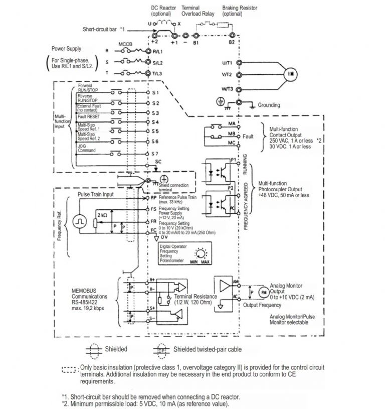
              Here is the complete diagram of the VFD:
              vfd potentiometer 3.jpg

              #441477
              Peter Graversen
              Participant
                @petergraversen11111
                Posted by SillyOldDuffer on 13/12/2019 13:36:03:

                In practice the difference between 12 and 10V probably doesn't matter, but I'd lose the excess volts with a resistor exactly as you propose. Why risk blowing the drive up for the few pence it costs to fit a resistor?

                There's an online calculator here. It suggests a standard value 390Ω resistor in series with a 2000Ω pot. 500Ω would be OK too – pots are often only ±20% accurate.

                But I'm worried about the input impedance. 20Ω is very low, and if true would seriously distort the calculation. I'd expect a much higher input value, say 20kΩ. Is 20Ω correct?

                Dave

                Hello Dave, and thank you for your kind reply. I was writing my previous post, while you were posting, so that's why my answer might have seemed odd.

                You are indeed right that i misreported the impedance – it is indeed 20k-ohm. I don't even know precisely what impedance is in this context, and what effect it has.

                vfd potentiometer 2.jpg

                I am ashamed to admit i don't even understand the calculator you linked to. I came to 500 ohm by thinking i would connect the resistor on the leg of the pot, that receives the 12v signal.

                So my maths was as follows. I want 10v with a 2K pot, so I=E/R.
                10v/2000ohm=0,005amp

                I want to lose 2v, so R=E/I
                2v/0,005amp=500ohm

                But i'm sure your calculation is correct. I will see if i can get my hands on a 390 ohm resistor.

                #441478
                Clive Foster
                Participant
                  @clivefoster55965

                  Peter

                  Way, way overthinking things.

                  When you use an external 10 V analogue input to control the VFD setting parameter n004 = 2 will also re-scale the input so 10 V is maximum speed. I suspect the external analogue control is actually a current loop rather than voltage.

                  When you use the on board 12 V source and potentiometer as per diagram maximum speed needs 12V, ie pot right at the end.

                  Presumably 12 V is provided to ensure that 10 V can be provided if the VFD is a master source for a current loop control despite some voltage drop over the wiring. I guess you'd select a suitable series resistor in that case.

                  Clive

                  Edited By Clive Foster on 13/12/2019 14:16:10

                  #441479
                  Peter Graversen
                  Participant
                    @petergraversen11111

                    Thank you for the concise answer Clive – i really appreciate it.

                    Your answer makes total sense. I just wanted to hook up a VFD to my drill press, and though "hey – there's one from a reputable company – i will buy that" .

                    Opening the manual was therefore quite a shock, where one is supposed to know term like impedance . I asked a electrician friend of mine, but he is old school, and couldn't answer me.

                    So all i wanted to know was, if i would fry something, if i just hooked up a 2K pot to the assigned terminals and changed the appropriate parameters, or if there is something everyone that own a VFD knows, that i didn't.

                    Thank you again .

                    Ps. People in here are really kind and helpful. What a cool forum.

                    #441484
                    Howard Lewis
                    Participant
                      @howardlewis46836

                      Comments from a purely mechanical engineer.

                      Impedance is akin to resistance, but only applies in an ac circuit, because it it is not comprised of pure resistance, (inductors and capacitors also have an influence which depends upon the frequency )

                      It sounds as if the 2K potentiometer is being used a a potential divider, with one end connected to ground (0 v ) and the other to the 12 v supply with the wiper providing the analogue voltage which causes the frequency to vary.

                      Experts please correct me if I am wrong!

                      Howardt

                      #441486
                      john fletcher 1
                      Participant
                        @johnfletcher1

                        I haven't noticed any one mentioning that the potentiometer should be a linear type.

                        Peter once you have got the drill working you may consider the following idea. If you wire in a reversing switch it is very handy. I drill 3mm hole, then adjust the speed to very slow, stop the machine. Next put 4 BA tap in the chuck, turn on the drilling machine again and very carefully pull down the quill so that the tap starts to make a thread. Just before the tap bottoms flick the reversing switch. Takes a bit of concentration, but works OK for me and I haven't broken a tap whilst doing it. Same with 6 BA. John

                        #441488
                        Norfolk Boy
                        Participant
                          @norfolkboy

                          I think Howard is correct, it is a simple voltage divider and the pot value can usually be about 2k – 10k ohms as it's job of division is all that is required. The 12 volts I believe is a red herring. (I have a Yaskawa and have no issues. I think where some of the confusion is coming from is that the analogue input can be used as a current measuring option instead of voltage reference. The reason being a long input cable may be subject to voltage issues through volt drop or interference wheras current is much more stable over distance. There will be a parameter somewhere to set this but voltage is usually the default.

                          Alan

                          #441491
                          john fletcher 1
                          Participant
                            @johnfletcher1

                            Back again, I forgot to mention my inverter is a Omron Sysdrive 3g3ev and the potentiometer is 2K linear. I've had the inverter on my drilling for more than 10 years and almost any very small single pole change over switch with centre OFF will be OK. John

                            #441493
                            Peter Graversen
                            Participant
                              @petergraversen11111

                              Howard,
                              I wouldn't presume to understand your explanation fully, but from what you are describing, the pot does indeed function as a divider.
                              On leg connected to 0v common terminal, the middle wiper "leg" to the frequency reference input terminal, and one to the 12v frequency reference power supply.

                              John, the 2K (2w) pot i have ordered had no mention of whether it was linear or not. I assume it is.
                              Your idea about using the VFD with a reverse switch is great. I had actually already ordered the parts for i, and even a foot switch, so i can activate reverse without using my hand.
                              That part of the wiring actually seems fairly simple .

                              #441496
                              Peter Graversen
                              Participant
                                @petergraversen11111

                                Thank you Norfolk,
                                Yeah – i'm feeling more and more sure, that the 12/10v thing is a non-issue. I actually JUST got an answer to an email i sent to Omron 4 days ago, 1 minute ago, and they were pretty laissez faire about it, just saying: Don't worry about the 12v, and just use a 2K resistor.". Thanks i guess .

                                The mechanical side, like hooking up SPDT switches etc. i'm comfortable with, so now the potentiometer crisis is over, i'm good to go .

                              Viewing 14 posts - 1 through 14 (of 14 total)
                              • Please log in to reply to this topic. Registering is free and easy using the links on the menu at the top of this page.

                              Advert

                              Latest Replies

                              Viewing 25 topics - 1 through 25 (of 25 total)
                              Viewing 25 topics - 1 through 25 (of 25 total)

                              View full reply list.

                              Advert

                              Newsletter Sign-up