Posted by derek hall 1 on 25/07/2020 06:13:58:..
I … never got further than drawing spur gears in isometric …
Spur gears in isometric projection are advanced stuff to me Derek. I did science A-Levels which came bundled with an hour a week of Technical Drawing. Just a taster – no exam at the end of it, and I'm pretty sure no gears were drawn. I may have been asleep!
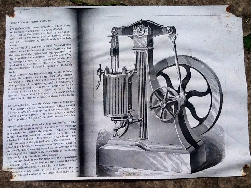
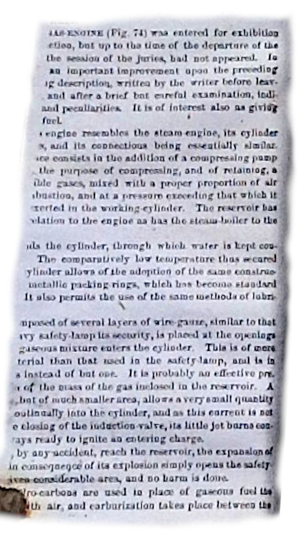
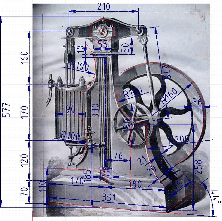
Anyway, on with homework. I've never attempted a job like this so it will be fun to see Jason's red-ink. The goal is to translate a 19th Century etching (which may not be technically accurate) into a number of patterns from which the castings needed to make a model can be produced. Ideally a working model!
I find this intimidating. But, another homework dodge, here's a development plan. Planning is another skilled job, but:
- Must have a defined goal (making patterns isn't the same as fabricating a working engine)
- Several Stages, each ending with defined products, peer reviewed with issues fixed or tolerated.
- Each stage broken down into a series of steps and resourced.
- Good plans have all the stages mapped out, but only the next stage fully detailed. Decisions ideally deferred so changes can be fed into later stages. Avoid developing a fully detailed end-to-end plan from the get go because these may turn into a Death March. Making it up on the fly is equally bad. OK when done by an experienced individual, comes completely off the rails as soon as a new boy tries it or expensive resources have to be coordinated. Try to find problems early; the cost of fixing mistakes multiplies by roughly 10 for each stage passed. Fixing a dimensional error in Stage 1 in CAD is dirt cheap, whilst the same boob missed until 500 castings have been sent could bankrupt the project.
Stage One: Gather Information, identify Risks & Issues, & Tooling
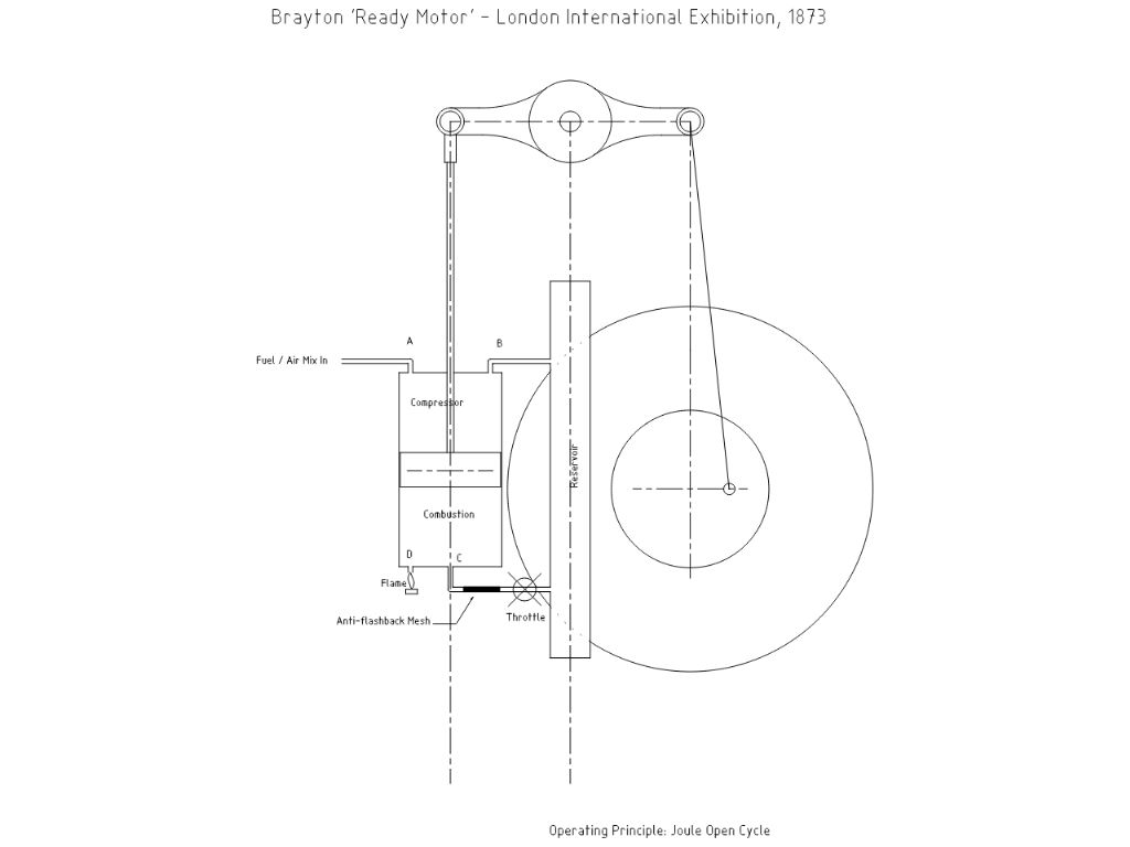
- How does the engine work? A. Brayton Open Cycle, issues for later:
- How is the engine be fuelled? Pressurised Gas/Air is risky
- How is the fuel ignited? Not clear from the drawing
- How is exhaust managed?
- Does it matter there's no governor?
- Is there an important relationship between fuel-pressure, reservoir size, and fly-wheel weight.
- As the cylinder burns and compresses fuel at the same time, what piston seal will keep flame away from the fuel mix. This is my only serious worry so far.
- Tools, chosen because I know them. You might prefer different
- Paper, pencil & calculator
- QCAD to collect dimensions from the image and approximate 3D coordinates. Also for doing 2D profiles.
- Fusion 360 for 3D modelling.
- Maybe a 3D printer to check scaled down parts.
- Establish dimensions, noting the drawing isn't isometric, & although probably realistic, is likely lacking details.
- Decide development strategy:
- Is it possible to model the engine realistically in 3D and then retrofit the model to produce patterns? (Noting Jason's hint about 'shrinkage allowance' )
- Should development 'fast-track' patterns, designing other parts to fit castings, or design patterns last to suit the working parts. My inclination is to give working parts top priority because it feels easier to design a frame to suit moving parts rather trying to squeeze a mechanism into a fixed frame.
Stage Two: Translate 2D Dimensions into Obvious 3D Parts
- Decide what the parts are. Many obvious, like cylinder, piston, flywheel, others less so. Is the bedplate/frame 1 part or 2? Is the top bearing block part of the frame or separate? Is the reservoir part of the frame or separate? Can the reservoir be cast into the frame directly, avoiding machining?
- Produce obvious parts in 3D and assemble to check rough fit. Adjust cosmetically so the engine looks authentic whilst making sure it will work in the real world. Candidates: Bedplate and frame, cylinder, wheels and crank-arm
Stage Three: Complex 3D Parts
- Candidates: piston assembly conrod, conrod fixings, fuel-intake fixtures, throttle, crankshaft, bearings, pipework, cross-head & guide. Adjust for standard size stock.
- Check fit by assembling with Stage 2 components, revising if needed. Note interference, assembly, fixing and other issues likely to cause practical problems later.
Stage Four: Nail Uncertainties
- Candidates: Exhaust, Lubrication, Fuel
Stage Five: Convert Preliminary Fit into Final Fit, Generate 2D Drawings, Review, Correct and Refine
Stage Six: Build and Test Prototype (Not necessarily the whole engine, or full-size, or in the real world.)
Stage Seven: Identify castings & develop patterns.
Stage Eight: Build a Real One
Stage Nine: Blame the Innocent and Reward the Guilty
Stage One progress:

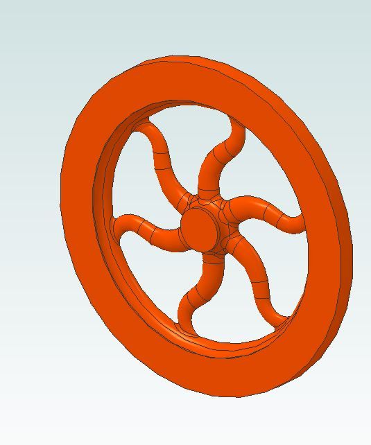
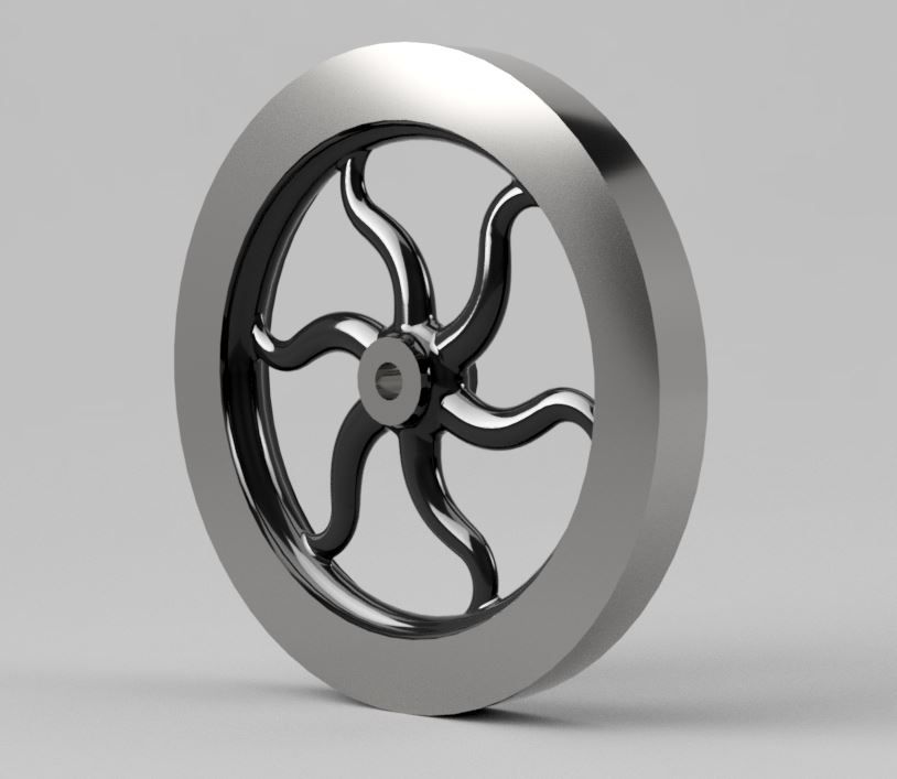
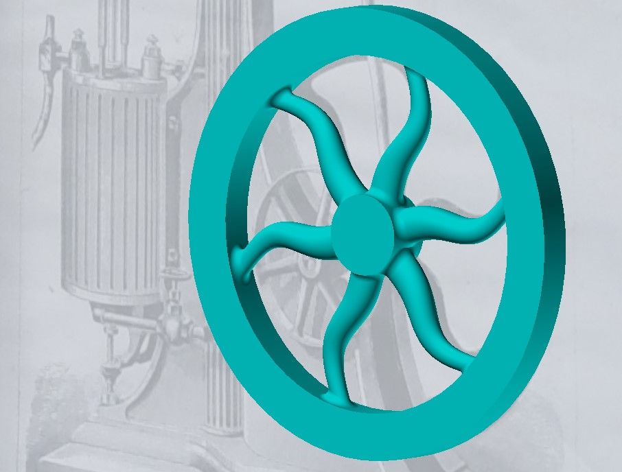
Jason's Flywheel has me worried. I'm not sure how to produce the 'S' shaped spokes in Fusion 360. Might be tricky. Time will tell.
Dave
Alyn Foundry.


