Old School Drawing Exercises and 2D CAD

Advert

Old School Drawing Exercises and 2D CAD

Home Forums CAD – Technical drawing & design Old School Drawing Exercises and 2D CAD

Viewing 25 posts - 76 through 100 (of 146 total)
  • Author
    Posts
  • #483703
    SillyOldDuffer
    Moderator
      @sillyoldduffer
      Posted by Neil Wyatt on 03/07/2020 11:57:51:

      Posted by Michael Gilligan on 03/07/2020 11:33:39:

      What remains of my brain is at risk of frying … So can anyone help me, please ?

      Taking Dave’s triangle as an example:

      We know that

      1. the centre of the inscribed circle is located at the intersection of the ‘bisectors’ of the three angles
      2. the centre of the circumscribed circle is located at the intersection the ‘perpendicular bisectors’ of the three sides

      So … There must be some elegant relationship between those two facts

      But what is it ?

      A geometric demonstration would be appreciated

      MichaelG.

      As a rider…

      There are actually THREE points defined solely by the triangle itself that all lie in a straight line.

      Michael has mentioned TWO, what is the THIRD?

      And what are their correct names (I had to look these up)?

      Neil

      Michael and Neil have caused a complete meltdown here. Now I know I know nowt about triangles!

      A guess; Neil means the centroid, incircle and orthocentre, all of which I had to look up and read four times. And there must be a million other triangle facts out there – my brain hurts.

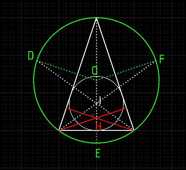
      Anyway, noticed this coincidence not mentioned by Wikipedia's Triangle entry. The inner circle is located by bisecting the angles (point I), whereas the outer circle (point O) is located by dropping verticals from the centre of each side. The coincidence is the white bisectors and green mid-verticals meet together on the perimeter of the outer circle when they're carried on outside the triangle (Points D, E and F).

      outerinner.jpg

      More! The orthocentre is found by dropping the red verticals at a right angle into the triangle's opposite corner. They cross at the orthocentre (Point H). If the red and green lines are also carried across the circle, they too meet on the perimeter.

      So all three centres I, H and O are all related to each other, and Point H is also the triangle's centre of gravity. There's deep logic in this I don't understand. Arggh!

      Dave

      Advert
      #483705
      blowlamp
      Participant
        @blowlamp

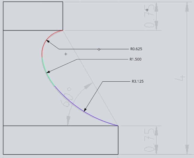
        Drawn with three arcs and it's not too far out, using SODs clue about the 1.5" arc.


        Martin.


        moulding.jpg

        Edited By blowlamp on 03/07/2020 16:16:09

        #483724
        pgk pgk
        Participant
          @pgkpgk17461

          Hang on.. this is a moulding so to replicate it you need the negative. Release agent and plaster may do the job..(ducks and runs..)

          pgk

          #483739
          Michael Gilligan
          Participant
            @michaelgilligan61133

            Posted by SillyOldDuffer on 03/07/2020 16:06:10:

            .

            Michael and Neil have caused a complete meltdown here. Now I know I know nowt about triangles!

            A guess; Neil means the centroid, incircle and orthocentre, all of which I had to look up and read four times. And there must be a million other triangle facts out there – my brain hurts.

            […]

            So all three centres I, H and O are all related to each other, and Point H is also the triangle's centre of gravity. There's deep logic in this I don't understand. Arggh!

            Dave


            .

            I’m sure you’re on the [long] road towards understanding, Dave

            Sorry not to have participated … I’ve been tinkering with microscopes, and leaving you to do all the work.

            MichaelG.

            .

            P.S. ___ Have you noticed that you are also, maybe, drawing a pentagram ?

            https://en.wikipedia.org/wiki/Pentagram

            Edited By Michael Gilligan on 03/07/2020 18:59:10

            #483757
            duncan webster 1
            Participant
              @duncanwebster1

              I'm still confused, the only constraints seem to be the 2 ends of the 60 degree construction line, and that fact that 1.5" radius comes into it somewhere. There are still an infinite number of solutions.

              #483762
              JasonB
              Moderator
                @jasonb

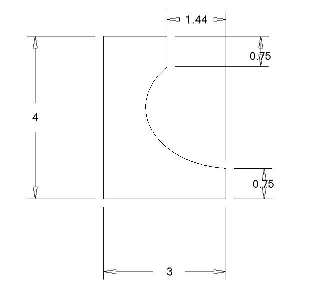
                How did I do? one line produced from a 1.5R semicircle

                daves latest.jpg

                #483809
                Georgineer
                Participant
                  @georgineer
                  Posted by Gary Wooding on 03/07/2020 13:54:44:

                  Posted by Neil Wyatt on 03/07/2020 12:57:44:

                  Posted by Georgineer on 03/07/2020 12:26:27:

                  This thread is taking some very interesting directions. Keep it up, lads!

                  And Neil,your knurler looks useful. Would it make a suitable subject for MEW?

                  George B.

                  It's not mine, it's Gary's!

                  Not 100% sure but I think the design looks familar.

                  Neil

                  It was published in issue 72 of MEW, called Yet Another Knurling Tool

                  Thanks Gary and Neil; I must learn to pay attention to detail. I'll look the article up. George B.

                  #483874
                  SillyOldDuffer
                  Moderator
                    @sillyoldduffer
                    Posted by JasonB on 03/07/2020 19:54:05:

                    How did I do? one line produced from a 1.5R semicircle

                    daves latest.jpg


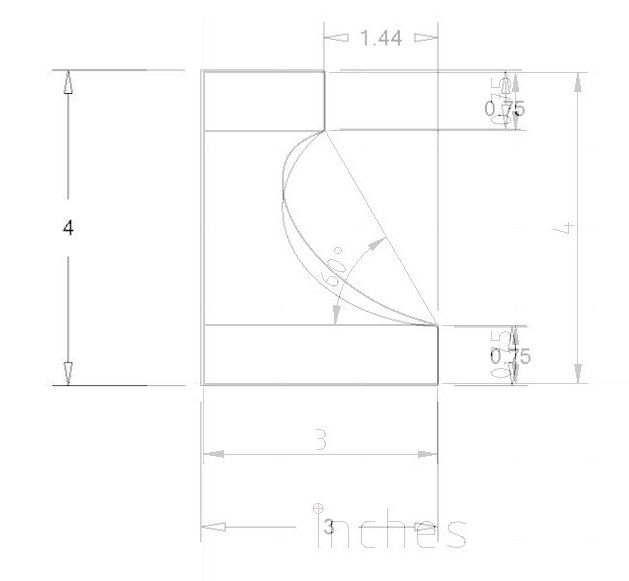
                    Fair effort, the curve is fuller than mine, I give it a B+, same mark I give my attempt at scaling and aligning our two drawings!

                    jasondave.jpg

                    Here's how my book does it:

                    mouldingsoln.jpg

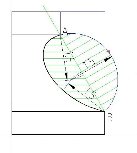
                    1. Find the origin of the blue 1.5" radius outer semicircle by drawing two 1.5R arcs from points A and B
                    2. Draw the blue semicircle and then several perpendiculars to it from the 60° line AB
                    3. Then draw connected horizontal lines of the same length, the ends of which define the required curve.

                    A CAD package should include a spline curve tool to span all the construction ends and draw a clean curve. The easiest way to join them manually is with a French curve tweaked to blend nicely by eye. Not as easy as it sounds to draw really smooth curves by hand, my attempts usually have obvious joins! And see Georgineer's post about being marked down for blending his curves too well in a City & Guilds exam!

                    Comment on the book method – unlike bending a spline, or picking a random French curve out of the box, it generates accurate reproducible dimensions for the maker. Whether or not the result more artistic than, say, Jason's fuller example is a matter of opinion. Might just be fashion, but some curves, like a Spitfire's wing, definitely look better  to most people. I've no idea why!

                    Dave


                    Edited By SillyOldDuffer on 04/07/2020 11:59:29

                    #483879
                    Michael Gilligan
                    Participant
                      @michaelgilligan61133

                      Posted by SillyOldDuffer on 04/07/2020 11:52:57:

                      […]

                      Might just be fashion, but some curves, like a Spitfire's wing, definitely look better to most people. I've no idea why!

                      Dave


                      .

                      I believe that's because they were laid-out full size, and were actual spline curves

                      … inherently beautiful because they are ‘natural’

                      MichaelG.

                      .

                      As an aside … I have just found [but not yet studied] this:

                      https://www.aerosociety.com/media/4843/the-spitfire-wing-planform-a-suggestion.pdf

                      Edited By Michael Gilligan on 04/07/2020 12:20:34

                      #483888
                      Gary Wooding
                      Participant
                        @garywooding25363

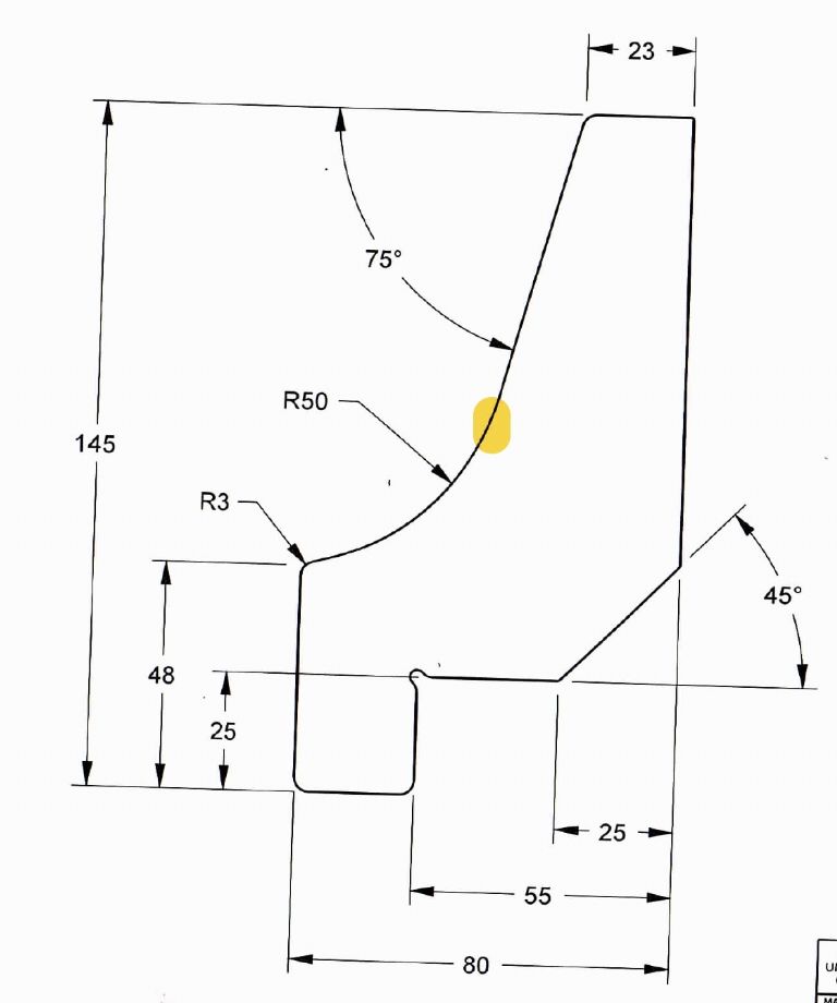
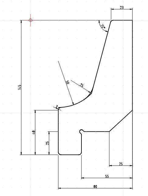
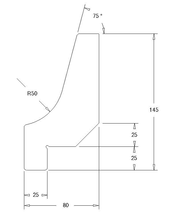
                        Here's a test that might be of interest. The yellow spot indicates a tangent.

                        cad drawing test.jpg

                        #483898
                        JasonB
                        Moderator
                          @jasonb

                          I did it a bit differently.

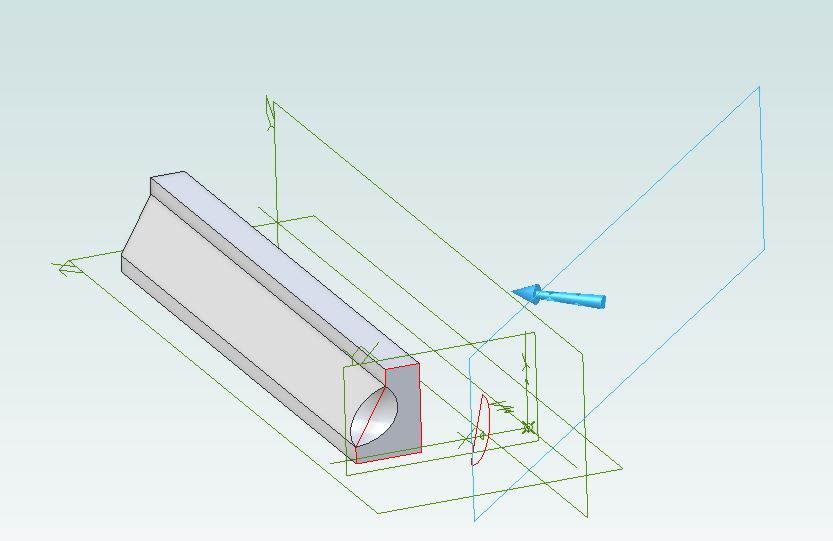
                          Drew out the shape with a diagonal lien inplace of teh curve and extruded that.

                          Added an additional plane at an angle, in this case 45deg

                          Drew the semicircle on the new plane and positioned it so the curve passes through the two points where angle meets vertical

                          Cut extrude the semicircle and the end view is what I posted, playing with the angle of the plane will alter the severity of the curve produced.

                          daves latest 2.jpg

                          #483918
                          SillyOldDuffer
                          Moderator
                            @sillyoldduffer
                            Posted by JasonB on 04/07/2020 13:21:00:

                            I did it a bit differently.

                            I like it, and there's a parallel between creating a new plane and my book's tilt a semicircle method.

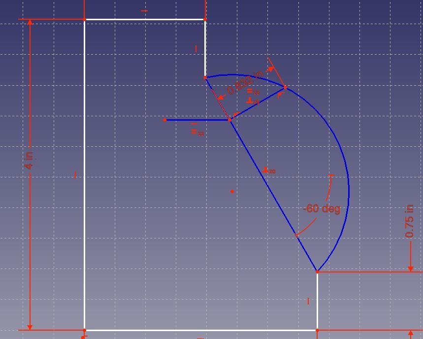
                            As expected I had trouble using the book approach with FreeCAD's Part Design Sketcher. The lack of Layers to hide construction detail makes it clumsy, and the need to Constrain everything is time-consuming. It can be done, but I made an early mistake in this model that takes a lot of backtracking to fix. The top dimension has floated to 0.751" because the sketcher honours an incorrect constraint, and it can't be forced to 0.750" without undoing several steps. Lots of constraint clutter in red already with many lines still to be added:

                            freecadmoulding.jpg

                            FreeCAD's sketcher makes a poor general purpose 2D drwaing aid. Of course it's not meant to be used as one! It has an easy to use Spline Tool. The draughtsman just adds a spline curve and shapes it to look pretty. The whole moulding can be drawn in a few minutes provided Old School exactitude isn't demanded.

                            freecadspline.jpg

                            and seconds later:

                            freecadmouldingext.jpg

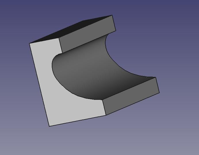
                            One more small step and my 3D printer could be churning a moulding out while I enjoy a glass of wine!

                            Dave

                            Edited By SillyOldDuffer on 04/07/2020 15:13:31

                            #484098
                            SillyOldDuffer
                            Moderator
                              @sillyoldduffer
                              Posted by Gary Wooding on 04/07/2020 12:50:20:

                              Here's a test that might be of interest. The yellow spot indicates a tangent.

                              cad drawing test.jpg

                              Certainly is, and I've awarded myself a 'C-, could do better'.

                              My version:

                              garystest.jpg

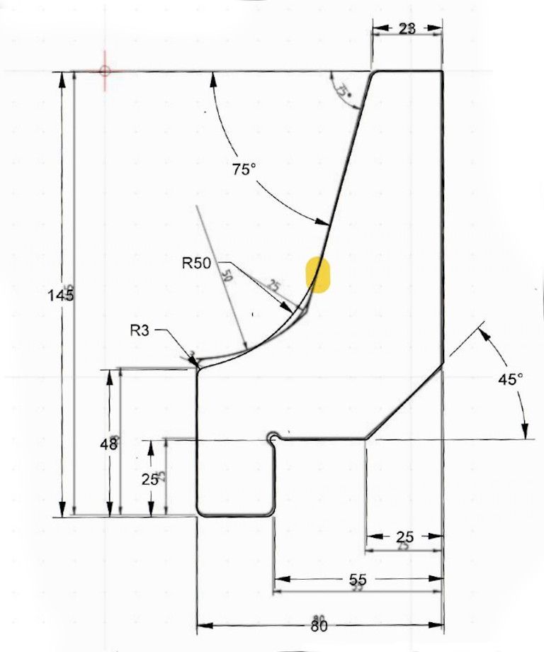
                              Not bad at first glance, but there are a few problems. First my R50 curve doesn't match Gary's, nor does my blend. Differences emerge when our drawings are overlaid:

                              garystestover.jpg

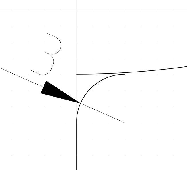
                              Thought logical at the time I've not positioned the origin of my 50mm radius curve correctly: it's too high. A second mistake pops out when the junction between R3 and R50 is zoomed into, the curves don't meet.

                              garyfail.jpg


                              On a hand drawing, the two curves failing to join wouldn't matter much; a human reading the drawing might not notice the gap or care. Fatal to 3D CAD and CAM though. That tiny gap is a serious error because the geometry described by the broken drawing is impossible. A 3D object can't be created from it. Drawings that look perfect are a common cause of 3D beginner frustration.

                              Not sure why my 50mm radius is wrong, I need to have another think. Gary can bask in glory while I retreat in confusion…

                              Dave

                              Edited By SillyOldDuffer on 05/07/2020 15:56:12

                              #484105
                              JasonB
                              Moderator
                                @jasonb

                                You should not need to place the origin of the 50mm radius. You just need it to be tangental to the angled line and intersect with the end of the 48mm vertical line. once that is do radius the junction.

                                drop moulding.jpg

                                Edited By JasonB on 05/07/2020 16:27:52

                                #484134
                                SillyOldDuffer
                                Moderator
                                  @sillyoldduffer
                                  Posted by JasonB on 05/07/2020 16:15:49:

                                  You should not need to place the origin of the 50mm radius. You just need it to be tangental to the angled line and intersect with the end of the 48mm vertical line. once that is do radius the junction.

                                  drop moulding.jpg

                                  Edited By JasonB on 05/07/2020 16:27:52

                                  Thanks Jason – I've been overthinking it!

                                  Dave

                                  #484136
                                  SillyOldDuffer
                                  Moderator
                                    @sillyoldduffer

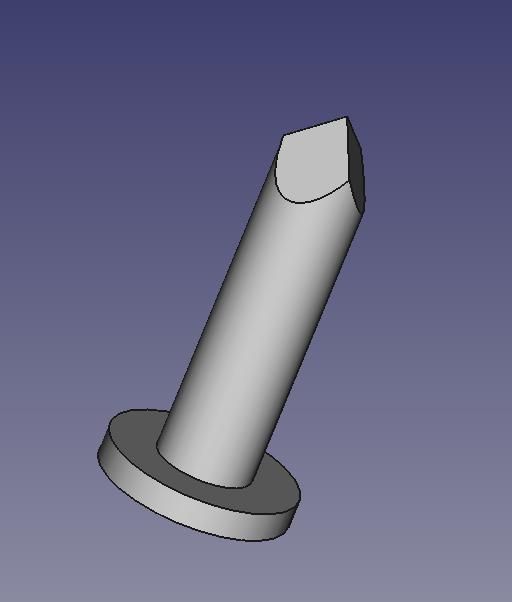
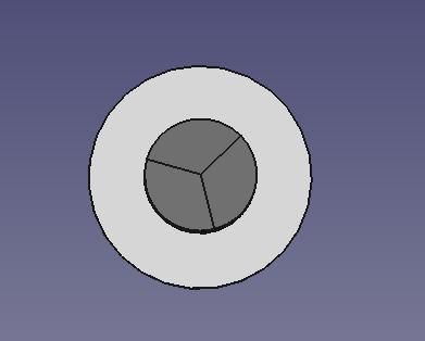
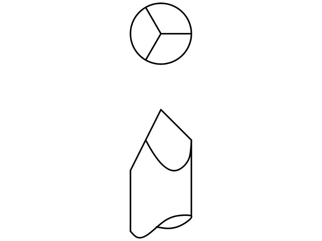
                                    A new challenge for 2D Draughtsmen is to produce First or Third Angle drawings of the sharp end of this tin-tack:

                                    tack.jpg

                                    tacktop.jpg

                                    Dimensions: tack is 10mm in diameter and 30mm long. The tip has 3-facets at 60°.

                                    The hard part of this one is correctly developing the curves where the flat facets meet the round body of the nail.

                                    I think it's an example of an object easier to make in the real world than it is to model in 3D, and considerably quicker to model in 3D than it is to formally draw in 2D. Hardest of all on a drawing board rather than CAD because of the multitude of construction lines that have to be erased to finish the drawing neatly.

                                    Trainee Draughtsmen were set many exercises like this and took years to become fully proficient. Old time engineering required immense skills and patience, it makes their work even more impressive.

                                    Dave

                                    #484982
                                    Nigel Graham 2
                                    Participant
                                      @nigelgraham2

                                      I was never a draughtsman professionally but did take GCE A-Level Technical Drawing, and Interpenetrations of which I think that tack would be an example, were one of the topics covered.

                                      It was not the most difficult topic though – I award that prize to something called "Lines in Space". Indeed, our teacher warned us if we didn't grasp the principles from the start we would be very unlikely to learn it! Despite sounding like an early Pink Floyd track, this method plots the shortest line between two lines crossing one above the other in a 3D space. It is fairly easy to visualise a solid, 3D object shown on a 2D sheet – until you venture into such realms as the innards of a Burrell compound cylinder casting, perhaps – but a line from one (x,y,z) to another (x,y,z) is a pretty nebulous entity. Now add another equally arbitrary 3D-sloping line, then try to imagine where they are at their closest, and how to draw them to establish that link accurately….

                                      I have no idea if CAD could give you the answer. Even if you knew the 4 co-ordinate trios the link-line would be fiendishly difficult to calculate mathematically, if possible at all. I have an idea too, we did not actually have the lines' start and end co-ordinates, but I forget how they were described. You'd need a third line and all crossing at a single point to use simultaneous equations with 3 unknowns, which is difficult and laborious algebra – here we start with only 2 lines unsociably distanced!

                                      '

                                      I don't think the industrial draughts-people many years back would necessarily have had to erase all the construction lines though, because the workshop prints were taken off ink tracings of the pencil drawings. ("Tracer" was our Mam's occupation, in fact!) That erasing would have been necessary in later years when drawing straight onto draughting-film (tracing-paper with a posh name). I worked as materials-cutter for several years for a printing-machine manufacturer, not long before CAD started to develop professionally, and all the original drawings there were on tracing-paper from which the shop prints used by the machinists and I, were photo-copied.

                                      #486857
                                      Gary Wooding
                                      Participant
                                        @garywooding25363

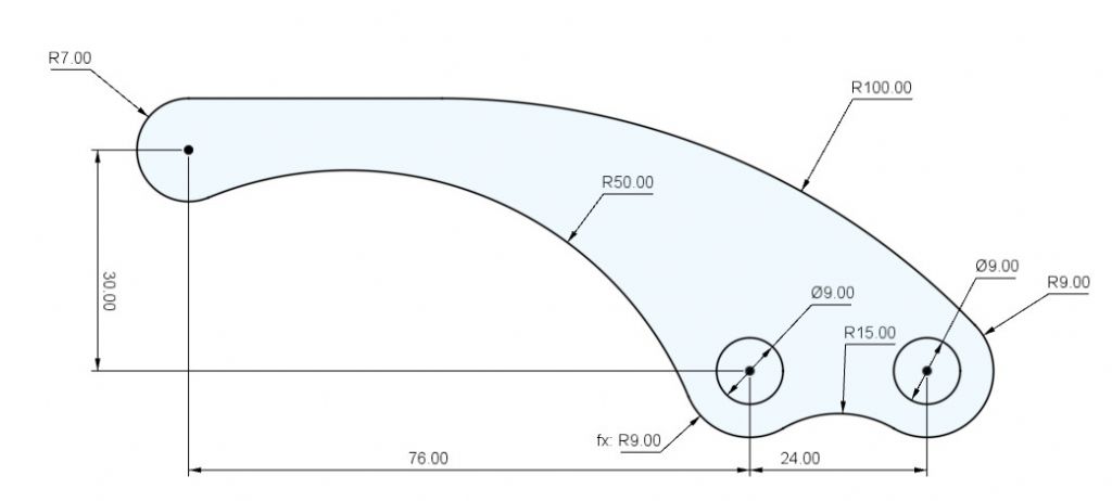
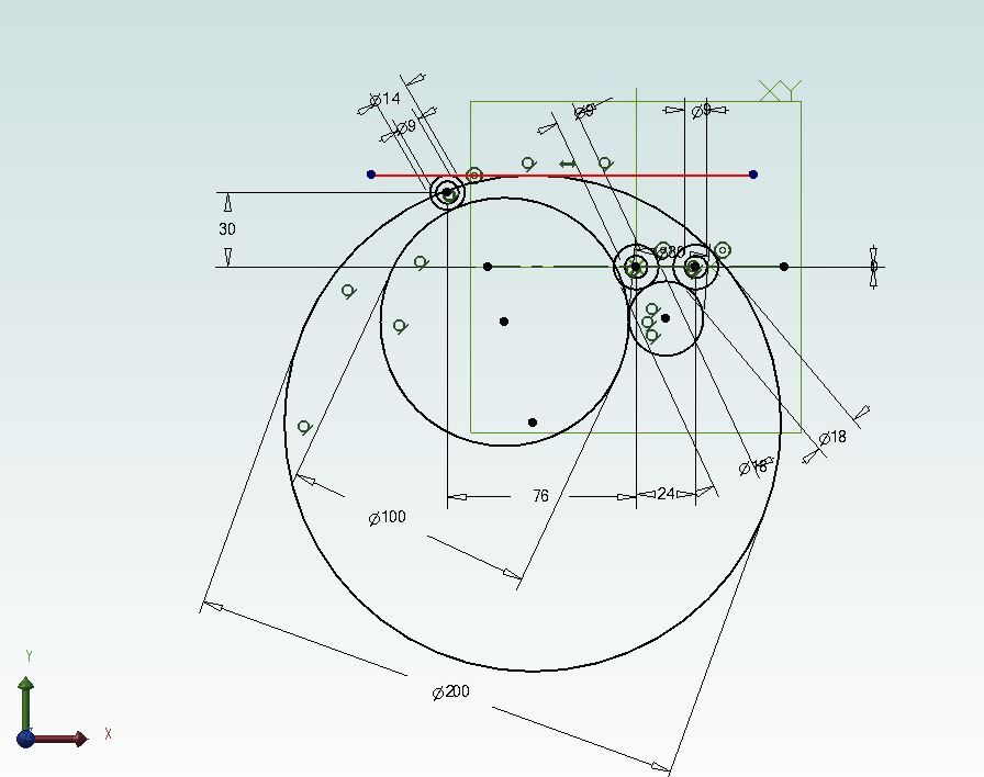
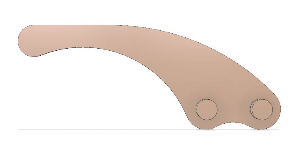
                                        Here's another challenge for you. All transitions are tangents, and the top line is horizontal.

                                        cad drawing test2.jpg

                                        #486861
                                        Martin Connelly
                                        Participant
                                          @martinconnelly55370

                                          Nigel, I think I did the shortest distance from a point to a plane and between two lines in space in A level maths. Also if I remember correctly the formula of the line of intersection of two planes. So much stuff has been pushed out of memory by time and new stuff to remember.

                                          Martin C

                                          #486912
                                          JasonB
                                          Moderator
                                            @jasonb

                                            Garry, don't you have anything more taxing as that one is quite easy. Just establish the 3 points draw some concentric circles then a few larger circles and a straight line before going to work with the tangent icon. then just trim away the excess.

                                            The only unknown are the two 9mm circles which being shaded may be a recess or projection the extent of either being unknown.

                                            july teaser 1.jpg

                                            july teaser 2.jpg

                                            #486925
                                            Meunier
                                            Participant
                                              @meunier
                                              Posted by Martin Connelly on 21/07/2020 10:37:04:

                                              //snip So much stuff has been pushed out of memory by time and new stuff to remember.

                                              Martin C

                                              I think it is called Buffer Overflow, have been blaming that for a few years now !
                                              DaveD

                                              #486946
                                              Gary Wooding
                                              Participant
                                                @garywooding25363
                                                Posted by JasonB on 21/07/2020 13:37:38:

                                                Garry, don't you have anything more taxing as that one is quite easy. Just establish the 3 points draw some concentric circles then a few larger circles and a straight line before going to work with the tangent icon. then just trim away the excess.

                                                Sorry, no.

                                                CAD simplifies things like this, but it's rather challenging with a manual drawing board.

                                                #486949
                                                SillyOldDuffer
                                                Moderator
                                                  @sillyoldduffer

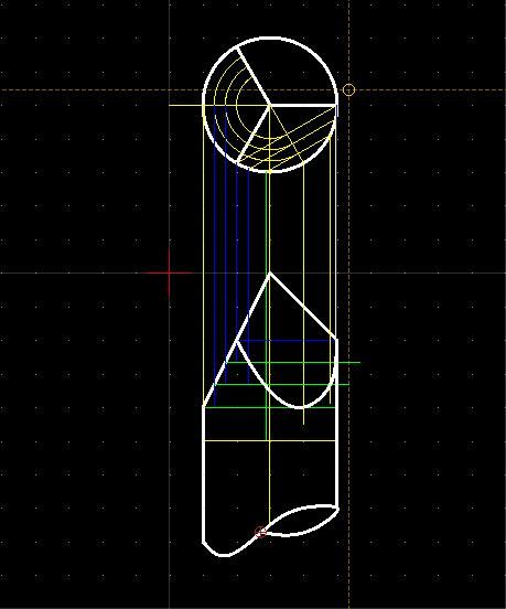
                                                  pointednail.jpg

                                                  With construction lines, done in different colours to highlight the intersections.

                                                  nailcons.jpg

                                                  CAD makes it easy to draw the curve along the construction, but I don't see any way QCAD might automate working out the intersections.

                                                  Gary's July challenge is easy in QCAD because the software does tangents at the click of a button, whoo hoo. Much harder with a Drawing Board I think.

                                                  Dave

                                                  #486957
                                                  duncan webster 1
                                                  Participant
                                                    @duncanwebster1
                                                    Posted by Gary Wooding on 21/07/2020 16:14:27:

                                                    Posted by JasonB on 21/07/2020 13:37:38:

                                                    Garry, don't you have anything more taxing as that one is quite easy. Just establish the 3 points draw some concentric circles then a few larger circles and a straight line before going to work with the tangent icon. then just trim away the excess.

                                                    Sorry, no.

                                                    CAD simplifies things like this, but it's rather challenging with a manual drawing board.

                                                    Why? you know the distance from the centres of the smaller circles to the bigger ones, so just strike arcs and draw circles tangential. (I'm so old I have used a spring bow pen and Indian ink to draw on linen sheets. Only to modify old drawings to be sure)

                                                    I wouldn't have done it like Jason, just draw the 3 smaller circles and the horizontal line and use the fillet tool

                                                    #486960
                                                    JasonB
                                                    Moderator
                                                      @jasonb
                                                      Posted by SillyOldDuffer on 21/07/2020 16:34:34:

                                                      . Much harder with a Drawing Board I think.

                                                      Dave


                                                      No really, just a case of swinging a few arcs

                                                      20200721_170707[1].jpg

                                                      Fillet won't do it in alibre as you can't select two complete circles

                                                      Edited By JasonB on 21/07/2020 17:12:46

                                                    Viewing 25 posts - 76 through 100 (of 146 total)
                                                    • Please log in to reply to this topic. Registering is free and easy using the links on the menu at the top of this page.

                                                    Advert

                                                    Latest Replies

                                                    Viewing 25 topics - 1 through 25 (of 25 total)
                                                    Viewing 25 topics - 1 through 25 (of 25 total)

                                                    View full reply list.

                                                    Advert

                                                    Newsletter Sign-up