Old School Drawing Exercises and 2D CAD

Advert

Old School Drawing Exercises and 2D CAD

Home Forums CAD – Technical drawing & design Old School Drawing Exercises and 2D CAD

Viewing 25 posts - 51 through 75 (of 146 total)
  • Author
    Posts
  • #483534
    Spurry
    Participant
      @spurry

      Ah, but that needs a set square, ruler and pencil in addition to the compasses. Is that allowed now? wink

      Pete

      Advert
      #483545
      IanT
      Participant
        @iant

        It's a rainy day outside (at least that's my excuse) so I've been amusing myself with Open SCAD.

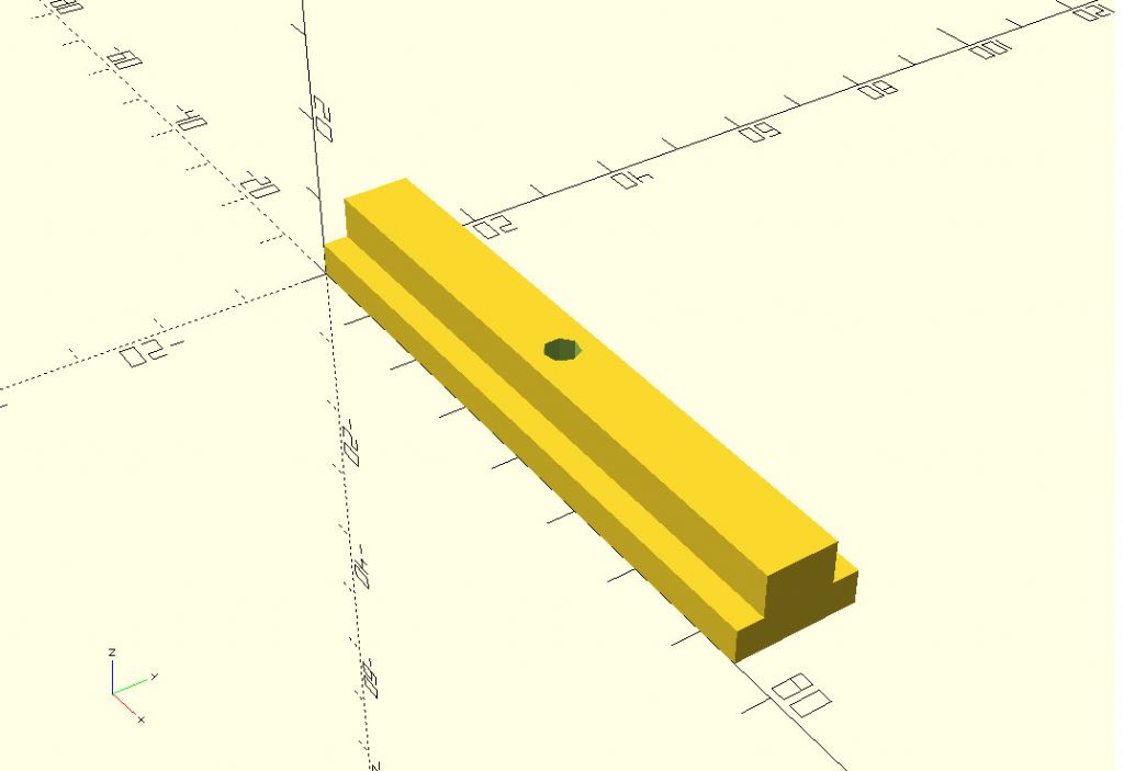
        There was a post recently about 3D printed T-Slot fillers. A nice simple thing to draw in 3D CAD (just sketch & extrude he says with new found confidence) but I thought I'd do it in SCAD (a much better use of coffee-time than Suduko!  )

        t_slot_filler.jpg

        Here is the script:

        //
        //
        // T-Slot Filler – IanT
        //
        L = 75; // T-Slot Length
        HR = 2; // Hole Radius
        BW = 14; // Bottom (of Slot) Width
        TW = 8; // Top (of Slot) Width
        BH = 4; // Bottom (of Slot) Height
        TH = 9; // Top (of Slot) Height
        //
        //
        difference () {
        union () {
        cube ([L,BW,BH], center=false);
        translate ([0,(BW/2-TW/2),0])
        cube ([L,TW,TH]); }
        translate ([L/2,BW/2,0])
        cylinder (TH,HR,HR);
        }

        I've used arbitrary dimensions above, so just change the variables to what you need. I've not printed this myself (I think it might actually be quicker to just cut some wooden strips and glue them together?) but it should be fine.

        You'll need to download Open SCAD and then just cut and paste the 'script' above into the Editor. For anyone not wanting to go "full-on" 3D CAD – Open SCAD can be learned in small steps and is pretty simple once you've got a few basics (it looks more complicated than it is) – and it also helps keep the little grey cells ticking over.

        Regards,

        IanT

        Edited By IanT on 02/07/2020 17:18:16

        #483548
        IanT
        Participant
          @iant

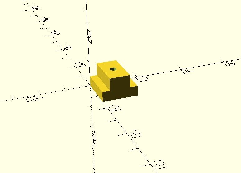
          It also occurred to me that a printed T-Nut might be useful for holding things in place (where no or low loads were involved) – such as DTI mounts etc…

          I just changed the length to 15mm and hole radius to 1.5mm (but would use tapping size in practice)

          short_filler.jpg

          Regards,

          IanT

          #483603
          Michael Gilligan
          Participant
            @michaelgilligan61133
            Posted by SillyOldDuffer on 02/07/2020 12:33:00:

            .

            Steps:

            1. Drop the vertical line AD
            2. Draw an arc from the corner ABC that crosses AD (in Blue on Diagram)
            3. Draw two circles from the each end of the blue arc where it meets AB and BC (Yellow on Diagram)
            4. Draw a line from B to the intersection of the yellow circles. (Light Blue on diagram) This line bisects the angle ABC, and where it crosses AD is the centre of the biggest circle that will fit inside the triangle.


            .

            With respect, Dave … Your Step 1 is cheating, and disqualifies you.

            But it’s simply a matter of adding the ‘mirror equivalent‘ of Steps 2&3 to locate the centre point.

            … This also provides a legitimate way of placing that vertical, by construction.

            MichaelG.

            Edited By Michael Gilligan on 03/07/2020 00:15:36

            #483608
            Nigel Graham 2
            Participant
              @nigelgraham2

              That SCAD code looks rather like something someone at work once gave me, called POV-Ray.

              Now, POV-Ray makes no pretence to be a CAD programme. It is or was intended to be purely artistic, and you can make it produce the most wonderful renderings of very pretty but utterly unfeasible or useless objects!.

              It too uses command-lines that are fairly simple to grasp and somewhat similar to that SCAD example; and although engineering-drawing is not its intended purpose I wonder if in fact it, or an up-to-date edition, could be used for making 3D-printer files.

              Something POV-Ray , or at least the version I have, lacks, are a grid or ruler-set, but I suspect you could make it generate at least a grid for the individual project.

              #483623
              SillyOldDuffer
              Moderator
                @sillyoldduffer

                Posted by Michael Gilligan on 03/07/2020 00:07:14:
                Posted by SillyOldDuffer on 02/07/2020 12:33:00:
                .
                Steps:
                1. Drop the vertical line AD
                2. Draw an arc from the corner ABC that crosses AD (in Blue on Diagram)
                3. Draw two circles from the each end of the blue arc where it meets AB and BC (Yellow on Diagram)
                4. Draw a line from B to the intersection of the yellow circles. (Light Blue on diagram) This line bisects the angle ABC, and where it crosses AD is the centre of the biggest circle that will fit inside the triangle.

                .
                With respect, Dave … Your Step 1 is cheating, and disqualifies you.
                But it’s simply a matter of adding the ‘mirror equivalent‘ of Steps 2&3 to locate the centre point.
                … This also provides a legitimate way of placing that vertical, by construction.
                MichaelG.

                Posted by Spurry on 02/07/2020 16:30:38:
                Ah, but that needs a set square, ruler and pencil in addition to the compasses. Is that allowed now?
                Pete

                To Pete, anything goes in my workshop. All's fair in Love, War and Model Engineering. Triple points for innovative cheating in my book, but don't try it in an Exam!

                To Michael, no need for the 'with respect' – like Ian's comment on dividing, you are completely orthogonal…

                smiley

                Dave

                #483636
                Michael Gilligan
                Participant
                  @michaelgilligan61133

                  Posted by SillyOldDuffer on 03/07/2020 08:56:29:

                  .

                  To Michael, no need for the 'with respect'

                  .

                  The respect is genuine, Dave

                  You have provided another thought-provoking exercise to keep the little grey cells active.

                  MichaelG.

                  #483642
                  Michael Gilligan
                  Participant
                    @michaelgilligan61133

                    Posted by SillyOldDuffer on 03/07/2020 08:56:29:

                    .

                    … you are completely orthogonal…

                    smiley

                    Dave

                    .

                    … upon which subject ^^^, allow me to throw this into the pot **LINK**

                    It’s a very nice proof of Thales’ Theorem

                    MichaelG.

                    #483654
                    Michael Gilligan
                    Participant
                      @michaelgilligan61133

                      What remains of my brain is at risk of frying … So can anyone help me, please ?

                      Taking Dave’s triangle as an example:

                      We know that

                      1. the centre of the inscribed circle is located at the intersection of the ‘bisectors’ of the three angles
                      2. the centre of the circumscribed circle is located at the intersection the ‘perpendicular bisectors’ of the three sides

                      So … There must be some elegant relationship between those two facts

                      But what is it ?

                      A geometric demonstration would be appreciated

                      MichaelG.

                      #483660
                      Neil Wyatt
                      Moderator
                        @neilwyatt
                        Posted by Michael Gilligan on 03/07/2020 11:33:39:

                        What remains of my brain is at risk of frying … So can anyone help me, please ?

                        Taking Dave’s triangle as an example:

                        We know that

                        1. the centre of the inscribed circle is located at the intersection of the ‘bisectors’ of the three angles
                        2. the centre of the circumscribed circle is located at the intersection the ‘perpendicular bisectors’ of the three sides

                        So … There must be some elegant relationship between those two facts

                        But what is it ?

                        A geometric demonstration would be appreciated

                        MichaelG.

                        As a rider…

                        There are actually THREE points defined solely by the triangle itself that all lie in a straight line.

                        Michael has mentioned TWO, what is the THIRD?

                        And what are their correct names (I had to look these up)?

                        Neil

                        #483662
                        Neil Wyatt
                        Moderator
                          @neilwyatt
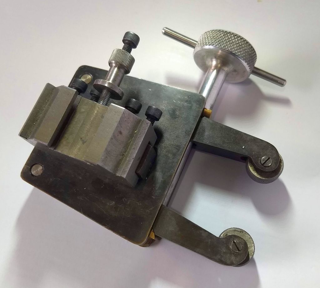
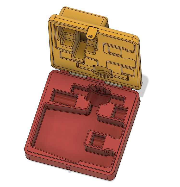
                          Posted by Gary Wooding on 02/07/2020 12:22:41:

                          I made this knurling tool some years ago and kept it in a cupboard together with 4 pairs of different knurls in a plastic bag. I often toyed with the idea of making a fitted box for it, but was put off by the awkward shapes. Eventually I bit the bullet, designed the 3D model in Fusion and am about to 3D print it.

                          2D CAD would have been very difficult.

                          knurler.jpg

                          knurler box.jpg

                          An excellent example, one great thing about 3D printing is the ability to incorporate clips and hinges.

                          Neil

                          #483666
                          SillyOldDuffer
                          Moderator
                            @sillyoldduffer

                            While I ponder Michael's problem and worry from his video if Thales is pronounced Thay Lees or Talez, here's another hard one. Well I think it's hard!

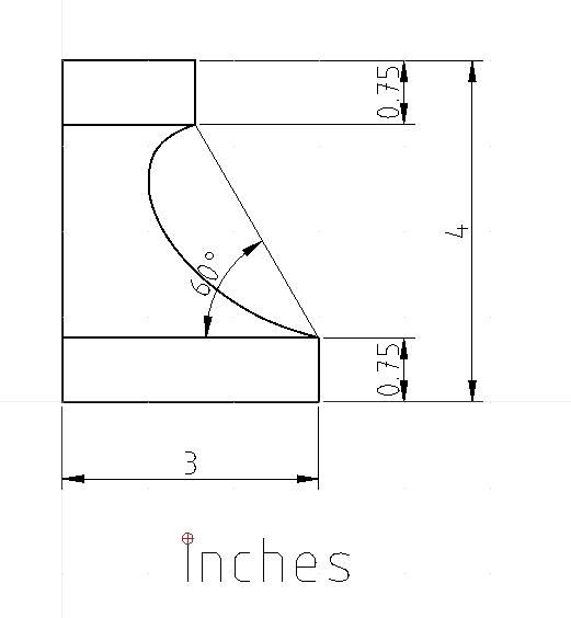
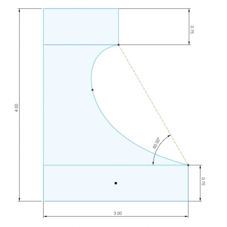
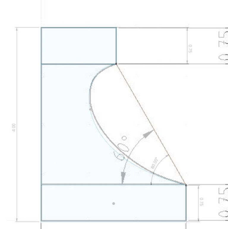
                            Replicate the curve of this moulding by whatever method. Clue – it's generated from a 1.5" radius semicircle, but the semi-circle's origin isn't on the 60° line. Whilst a CAD package can draw the spline curve given relatively few points to follow, producing a 'fair curve' manually needs several.

                            moulding.jpg

                            Nigel complained about hard-to-make drawings and this might be a good example! But shapes like this are common in the real-world. Streamlining and decorative work demand tricky curves, and made cheaply too! My stair bannister is an example, and dining room coving is another. No sympathy for the poor old tool-maker – the curve has to look right!

                            Dave

                            #483667
                            Georgineer
                            Participant
                              @georgineer

                              This thread is taking some very interesting directions. Keep it up, lads!

                              And Neil,your knurler looks useful. Would it make a suitable subject for MEW?

                              George B.

                              #483668
                              Georgineer
                              Participant
                                @georgineer

                                SOD, when my wife worked for the engineering firm Thales it was pronounced Tallis!

                                G.

                                #483674
                                Neil Wyatt
                                Moderator
                                  @neilwyatt
                                  Posted by SillyOldDuffer on 03/07/2020 12:23:07:

                                  While I ponder Michael's problem and worry from his video if Thales is pronounced Thay Lees or Talez, here's another hard one. Well I think it's hard!

                                  Replicate the curve of this moulding by whatever method. Clue – it's generated from a 1.5" radius semicircle, but the semi-circle's origin isn't on the 60° line. Whilst a CAD package can draw the spline curve given relatively few points to follow, producing a 'fair curve' manually needs several.

                                  moulding.jpg

                                  Nigel complained about hard-to-make drawings and this might be a good example! But shapes like this are common in the real-world. Streamlining and decorative work demand tricky curves, and made cheaply too! My stair bannister is an example, and dining room coving is another. No sympathy for the poor old tool-maker – the curve has to look right!

                                  Dave

                                  With CAD the curve is best done as a simple bezier with a control point at each end. Trivially simple.

                                  Manually just as easy using French curves, the hard bit being finding mine if they turn out not to be where I put them years ago…

                                  Neil

                                  #483675
                                  Neil Wyatt
                                  Moderator
                                    @neilwyatt
                                    Posted by Georgineer on 03/07/2020 12:26:27:

                                    This thread is taking some very interesting directions. Keep it up, lads!

                                    And Neil,your knurler looks useful. Would it make a suitable subject for MEW?

                                    George B.

                                    It's not mine, it's Gary's!

                                    Not 100% sure but I think the design looks familar.

                                    Neil

                                    #483676
                                    duncan webster 1
                                    Participant
                                      @duncanwebster1

                                      SODs latest:

                                      assuming we are to use 2 arcs, unless both radii are specified there are an infinite number of solutions

                                      #483681
                                      blowlamp
                                      Participant
                                        @blowlamp

                                        My best guess for the centre location of the 1.5" rad arc is at about 2.5" to the right & 1.5" down from the top/left corner. I'm suspecting a 0.625" rad arc at the top and a 3.125" rad arc at the bottom to join all three together tangentially.

                                        Martin.

                                        #483685
                                        Gary Wooding
                                        Participant
                                          @garywooding25363

                                          How about this?

                                          mecadprob2.jpg

                                          #483688
                                          Gary Wooding
                                          Participant
                                            @garywooding25363
                                            Posted by Neil Wyatt on 03/07/2020 12:57:44:

                                            Posted by Georgineer on 03/07/2020 12:26:27:

                                            This thread is taking some very interesting directions. Keep it up, lads!

                                            And Neil,your knurler looks useful. Would it make a suitable subject for MEW?

                                            George B.

                                            It's not mine, it's Gary's!

                                            Not 100% sure but I think the design looks familar.

                                            Neil

                                            It was published in issue 72 of MEW, called Yet Another Knurling Tool

                                            #483689
                                            SillyOldDuffer
                                            Moderator
                                              @sillyoldduffer
                                              Posted by Neil Wyatt on 03/07/2020 12:56:48:

                                              Posted by SillyOldDuffer on 03/07/2020 12:23:07:

                                              With CAD the curve is best done as a simple bezier with a control point at each end. Trivially simple.

                                              Manually just as easy using French curves, the hard bit being finding mine if they turn out not to be where I put them years ago…

                                              Neil

                                              CAD may make drawing Bezier curves easy thank goodness, but are they trivially simple?

                                              bezier.jpg

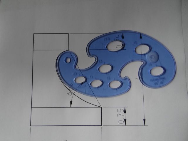
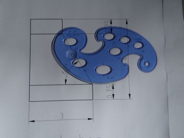
                                              Doing this manually, I'd use a French curve at different angles to fair the curve, but it would be lucky to find an exact match. One of mine comes close, but not at both ends:

                                              dsc06286.jpg

                                              two or moredsc06285.jpg

                                              And someone designed that French curve on a drawing board in the first place! How was it done?

                                              Re Duncan's comment, I'm afraid the curve isn't drawn with arcs. (Maybe it could be?)

                                              Once the approach is explained, easy enough to do manually, with Qcad, or with any other competent 2D CAD package. Not sure about FreeCAD & Fusion360's sketch tools for this particular job. They might not have the 2D primitives needed to construct the curve. (I haven't checked.) They can both do spline curves, but in this example it might be easier to construct the outline in 2D CAD and import the answer rather than sketch it.

                                              Dave

                                              #483692
                                              Gary Wooding
                                              Participant
                                                @garywooding25363
                                                Posted by SillyOldDuffer on 03/07/2020 13:55:13:

                                                Once the approach is explained, easy enough to do manually, with Qcad, or with any other competent 2D CAD package. Not sure about FreeCAD & Fusion360's sketch tools for this particular job. They might not have the 2D primitives needed to construct the curve. (I haven't checked.) They can both do spline curves, but in this example it might be easier to construct the outline in 2D CAD and import the answer rather than sketch it.

                                                Dave

                                                My effort was done with Fusion sketch. What's wrong with it?

                                                #483693
                                                SillyOldDuffer
                                                Moderator
                                                  @sillyoldduffer
                                                  Posted by Gary Wooding on 03/07/2020 13:45:41:

                                                  How about this?


                                                  mecadprob2.jpg

                                                  Pretty close, your curve goes slightly deeper than mine:

                                                  garymatch.jpg

                                                  I'm not complaining!   Fusion did better than I thought it would!

                                                  Dave

                                                  Edited By SillyOldDuffer on 03/07/2020 14:16:39

                                                  #483694
                                                  Michael Gilligan
                                                  Participant
                                                    @michaelgilligan61133
                                                    Posted by SillyOldDuffer on 03/07/2020 13:55:13:

                                                    And someone designed that French curve on a drawing board in the first place! How was it done?

                                                    .

                                                    Not sure … but I think it is literally a spline curve, so created with a suitably springy flexible strip and some pins.

                                                    MichaelG.

                                                    #483699
                                                    Martin Connelly
                                                    Participant
                                                      @martinconnelly55370

                                                      To me it looks like the curve produced by rotating a circle 45 degrees in two planes. At 1.5 radius this would produce an oval 3 high 2.12 wide. Rotate this 45 degrees anticlockwise to produce the example given.

                                                      Martin C

                                                    Viewing 25 posts - 51 through 75 (of 146 total)
                                                    • Please log in to reply to this topic. Registering is free and easy using the links on the menu at the top of this page.

                                                    Advert

                                                    Latest Replies

                                                    Viewing 25 topics - 1 through 25 (of 25 total)
                                                    Viewing 25 topics - 1 through 25 (of 25 total)

                                                    View full reply list.

                                                    Advert

                                                    Newsletter Sign-up