Old School Drawing Exercises and 2D CAD

Advert

Old School Drawing Exercises and 2D CAD

Home Forums CAD – Technical drawing & design Old School Drawing Exercises and 2D CAD

Viewing 25 posts - 26 through 50 (of 146 total)
  • Author
    Posts
  • #483442
    JasonB
    Moderator
      @jasonb

      I've given up on Dave's latest challenge, spent all night trying to draw the basic triangle with just a compass and failed, let alone getting a circle to fit insidewink

      Advert
      #483444
      Anonymous
        Posted by SillyOldDuffer on 01/07/2020 17:40:18:

        Another Geometrical Drawing. What's the radius of the largest circle that can be drawn inside this isosceles triangle?

        Should be able to solve it analytically, although that will involve maths. smile o

        Andrew

        #483448
        pgk pgk
        Participant
          @pgkpgk17461
          Posted by JasonB on 02/07/2020 07:21:34:

          I've given up on Dave's latest challenge, spent all night trying to draw the basic triangle with just a compass and failed, let alone getting a circle to fit insidewink

          Very difficult to draw the outline of a triangle without a ruler but I'd guess that drawing enough circles round a circle of same radius and building them up gives a grid from which you could pick the proportionate points or even create a virtual graph paper?? I'm just too lazy to try.

          As an intuitive assessment I'd reckon that a circle within a square whose top is near as dammit 12 squares up from the bottom should do it and use the compass to measure that diagonal over the circle points created?

          There's probably some more sane way of doing it.

          pgk

          #483451
          Former Member
          Participant
            @formermember32069

            [This posting has been removed]

            #483452
            IanT
            Participant
              @iant
              Posted by Nigel Graham 2 on 02/07/2020 01:58:49:

              So why 3D CAD for own drawings for own projects in own workshops…?

              The only answers I can see are that either you have the desire, time and ability to learn it, or you've bought a CAD package that gives you no choice!

              An interesting question Nigel and the answer will be dependent on quite a few factors.

              I have used TurboCAD DL for many years and regard myself as proficient (rather than expert). For some simple 2D outlines, I might still use it, although it is not parametric. I tried 3D in TC/DL and failed dismally. My approach to a drawing was to get everything into model space somewhere (often several iterations for different 'edits' ) and sort things out via 'views'. So you are drawing at a global level in one sense. I spent a lot of time using construction lines to ensure different projections were matched dimensionally. I also made extensive use of layers in term of separating 'bits' from each other…

              2D might have been sufficient for my needs until I purchased a 3D printer, at which point I wanted much more specific designs than Thingiverse was ever going to provide. A friend recommended Open SCAD and it was a very good solution for my relatively simple 3D print needs. I have used existing SCAD models, modified them and also created my own. It is a simple and elegant tool that can be learned in small steps and used almost instantly. Given its 'designs' are text based, it is also a very good (easy) way to share 'things' with others. I would use it to teach children about 3D concepts rather than a more complex 3D CAD system.

              However, SCAD will never be my 'engineering' design tool of choice (simply one of my 3DP 'tools' )  For something to replace TC/DL I wanted a 3D package that was modern, powerful and that I could actually manage to learn. Cost was a factor and content ownership (e.g. Cloud based?) another. Plenty of debate here about which 3D package is the best but for me Solid Edge seems to fit my requirements. I've been learning and using it for a few weeks now and I'm very happy with all I've discovered.

              One of the things that is very different of course, is the change in design thought processes. The SE system forces my to think of everything as 'parts' and 'assemblies' (and the hierarchy of sub-assemblies etc). I can define the parts material and many other aspects of the design – which immediately tends to promote other decisions – shall I print this part or machine it? Could that small spacer piece be hardwood, metal or 3D printed? How would I fabricate this part (or should I even try – if it requires more/smaller parts).

              I've found the journey most interesting and enjoyable. Whether I am a better or more productive modeller, I'm not sure at the moment but it's been fun and that's why I do this stuff – for my personal satisfaction and entertainment.

              Take Care Everyone

              IanT

              Edited By IanT on 02/07/2020 09:53:12

              #483461
              Gary Wooding
              Participant
                @garywooding25363

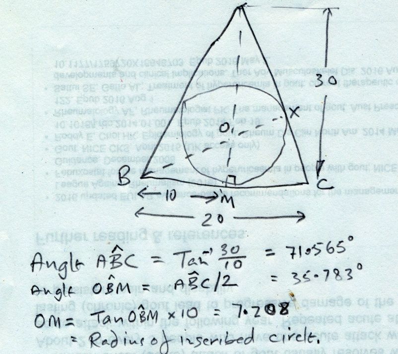
                No CAD, no compass, no ruler, just pencil and trig.

                Do I get double points?

                me cad.jpg

                #483463
                Former Member
                Participant
                  @formermember32069

                  [This posting has been removed]

                  #483465
                  Martin Connelly
                  Participant
                    @martinconnelly55370

                    We had a drawing of a pipe at work, done by a professional draughtsman with years of experience, that I had to point out was impossible to make. He said if we can draw it you can make it. What he had drawn was the equivalent of a Penrose triangle. If he had 3D CAD it would have been obvious but he was doing it 2D. I learnt to use AutoCad when it was 2D from the supplied paper manual that had a very good tutorial to work through. I was also lucky enough to be doing it at work so effectively was paid to learn it. Going to 3D was not hard as I spent a lot of time at work checking drawings for production before they were issued. You learn to turn 2D images into your own internal 3D model as a result.

                    The triangle problem is simple, learnt that in maths at school. Bisect one of the base angles and project the line to the centre line. Estimate by eye gives 7, trig gives 7.2 if I remember yesterday's result correctly.

                    Martin C

                    #483468
                    Neil Wyatt
                    Moderator
                      @neilwyatt

                      Bisect two angles of the triangle, three arcs per vertex.

                      Centre the triangle where the bisecting lines cross.

                      Draw a circle tangential to the sides of the triangle.

                      Blimey must be remembering that from school.

                      Neil

                      Edit: (Works with all triangles and strictly you only need to bisect two angles, thinking about it!)

                      Edited By Neil Wyatt on 02/07/2020 11:08:07

                      #483470
                      blowlamp
                      Participant
                        @blowlamp

                        Easy in CAD whichever way you do it. smiley

                        #483474
                        pgk pgk
                        Participant
                          @pgkpgk17461
                          Posted by Neil Wyatt on 02/07/2020 11:06:02:

                          Bisect two angles of the triangle, three arcs per vertex.

                          Centre the triangle where the bisecting lines cross.

                          Draw a circle tangential to the sides of the triangle.

                          Blimey must be remembering that from school.

                          Neil

                          Edit: (Works with all triangles and strictly you only need to bisect two angles, thinking about it!)

                          Edited By Neil Wyatt on 02/07/2020 11:08:07

                          ..so you cheated and used a straight edge..folding might have been permitted…

                          pgk

                          #483475
                          SillyOldDuffer
                          Moderator
                            @sillyoldduffer
                            Posted by pgk pgk on 01/07/2020 22:26:21:

                            70mph round a 100 metre curve? I'd guess you're tilting it 90 degrees and fitting ejector seats…

                            pgk

                            Absolutely! Engineering is about balancing cost and practicality, and it isn't easy. Given the clue that the operators wish to maintain an average 70mph over the length of the line, the engineer must pay careful attention to the design of this reverse curve. He can't assume it's OK for trains to take the curve at 5mph; the curve has to be optimised for speed. As building railway line is too expensive to let practical men experiment on the job, this was done with drawing boards, slide rules and maths in an office.

                            So what is the maximum speed a train can be safely taken round a well-designed 100 metre curve? Transition curves and super-elevation (banking) allowed.

                            In the history of railway building, it was common for lines to be routed cheaply at first because money was short. They put up with slow tight curves, gradients, weak bridges, and long diversions even though these hack profits down year on year. When money was available later inefficiencies were often eliminated by building cut-offs. A good way of getting rid of a reverse curve is to connect both sides with a direct tunnel or viaduct, but these have to pay for themselves by increasing the railways efficiency. No place for practical men in this type of engineering either – it's all about cost estimating. Practical men have the skills needed dig tunnels, but the hard part is making the railway pay.

                            Dave

                            #483478
                            Neil Wyatt
                            Moderator
                              @neilwyatt

                              I think the values of 3D CAD is very much in it's flexibility to meet the different needs of different people.

                              It goes without saying that those of us who use CAM or 3D printing would be lost without 3D CAD.

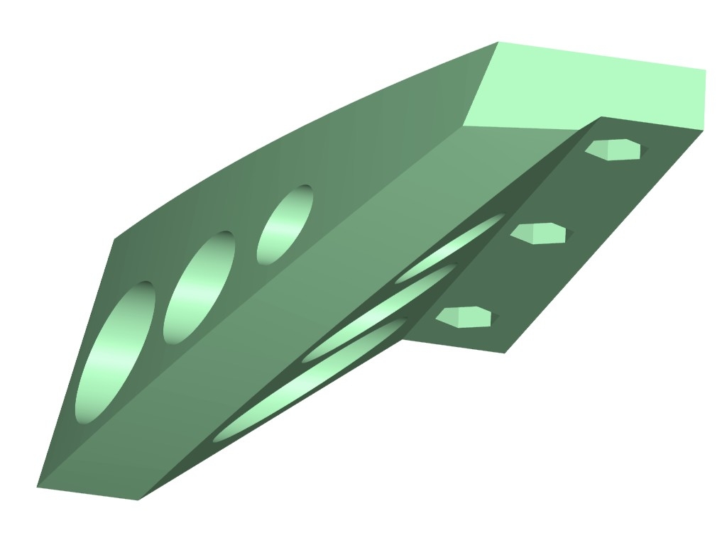
                              The sector for my equatorial platform (below) has curves in two intersecting planes, as a result of the bottom surface being an inclined slice of a cone. Not only is it elliptical, but curved and tapered too. Tricky to draw in 2D but with significant advantages over the traditional circular (the load is borne vertically, not at 38 degrees to the horizontal) and elliptical (the load bearing point moves back an forth) designs. It also needs to be reasonably accurate to work well, although any errors are mitigated by the large radii ( about 383mm and 500mm).

                              Making it in wood or metal would require CNC or a very large jig. 3D printing, it's almost as easy as making any other shape (just some thought about support placement and orientation needed).

                              For me, then, 3D Cad opens doors that would otherwise be closed.

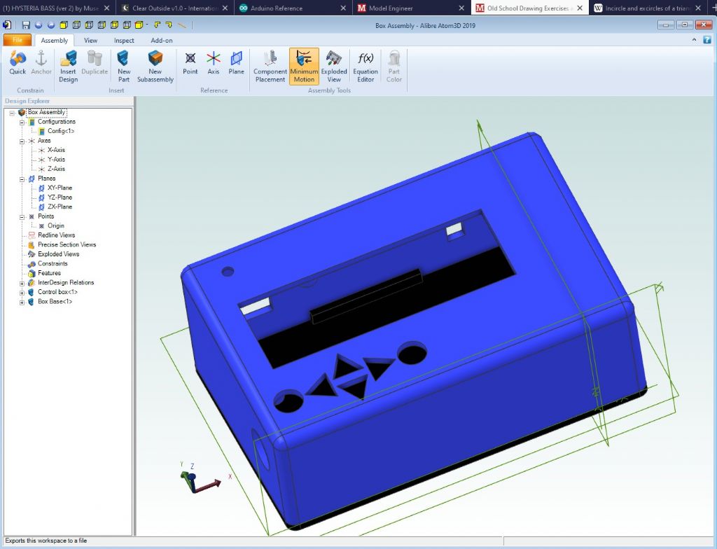
                              Another example is this control box. Aside from 3D printing it it would not be hard to draw it on paper in 2D, but I would have had to construct an isometric view to get a real feel for how it would look. When aesthetics as well as function are important, 3D CAD win hands down.

                              Incidentally, most of the making of this box was effectively working in 2D, but being able to create angled planes and project of existing surfaces greatly eases tasks like creating the close fitting tabs on the angled base.

                              control box alibre.jpg

                              I do use a very basic 2D CAD (a ~20-year-old version of Corel Draw) for some tasks, like setting out telescope optics. When I made a telescope with a Crayford focuser, although 2D (actually in TurboCAD) was useful for calculating the overall dimensions, I switched to 3D to get the proportions right before cutting metal. It this case my 3D 'model' wasn't very developed at all, but without it most of the work would have been 'cut and try'.

                              I think people often forget that 3D CAD and do anything 2D can do, with the advantage of instantly viewing results in 3D, if desired.

                              Many of the uses and advantages of 3D CAD I've found are not obvious and you tend to discover them through your projects, rather than being led by the capabilities of the CAD. The other thing is how you learn by doing. My designs are much more efficient now – for example I've learned to create one feature then mirror or pattern it rather than drawing them all individually. This means if there's a change you just edit the original, a huge timesaver.

                              Neil

                              #483483
                              Neil Wyatt
                              Moderator
                                @neilwyatt
                                Posted by SillyOldDuffer on 02/07/2020 11:30:30:

                                In the history of railway building, it was common for lines to be routed cheaply at first because money was short. They put up with slow tight curves, gradients, weak bridges, and long diversions even though these hack profits down year on year. When money was available later inefficiencies were often eliminated by building cut-offs. A good way of getting rid of a reverse curve is to connect both sides with a direct tunnel or viaduct, but these have to pay for themselves by increasing the railways efficiency. No place for practical men in this type of engineering either – it's all about cost estimating. Practical men have the skills needed dig tunnels, but the hard part is making the railway pay.

                                Dave

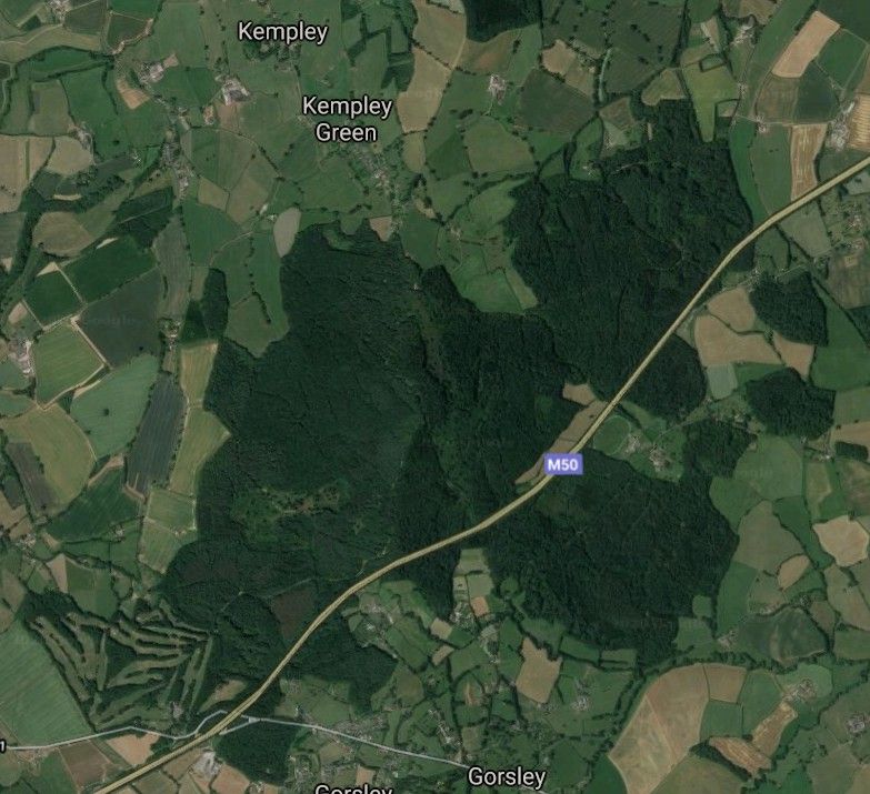
                                Move onto to motorway and major road design and construction up to the 1970s and 80s… woodland had a lower cost per acre than farmland so planning could be a sort of ecological 'join the dots'.

                                Look at this example on the M50 where the planners managed to neatly align a couple of miles of the motorway just inside the woodland…

                                woodland m50.jpg

                                #483484
                                pgk pgk
                                Participant
                                  @pgkpgk17461
                                  Posted by SillyOldDuffer on 02/07/2020 11:30:30:

                                  So what is the maximum speed a train can be safely taken round a well-designed 100 metre curve? Transition curves and super-elevation (banking) allowed.

                                  Dave

                                  I'll start by stating that I ain't gotta clue about the limitations applying to a real world case but in my world with unlimited lead-in (transition) and no issues regarding wheelbase or suspension or carriage length or engine type then the only limit should be design to cope with the aerodynamics of breaking the sound barrier and the G-force limitations on the driver. Make it autonomous as a train and your limitation becomes dependant on available power – you'll never get anywhere near C but a good chance that wat comes out of the bend is a thin superheavy new alloy.

                                  pgk

                                  #483494
                                  Gary Wooding
                                  Participant
                                    @garywooding25363

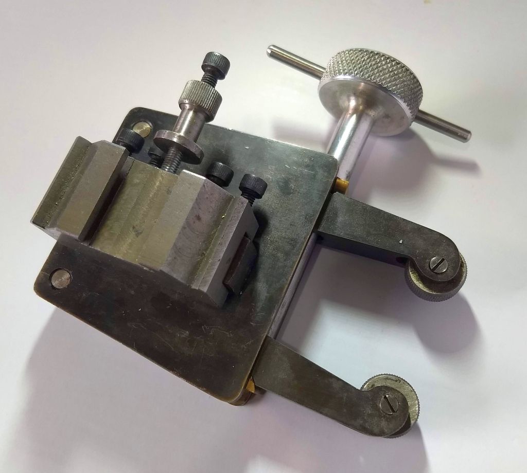
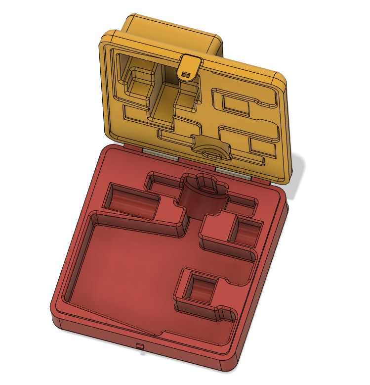
                                    I made this knurling tool some years ago and kept it in a cupboard together with 4 pairs of different knurls in a plastic bag. I often toyed with the idea of making a fitted box for it, but was put off by the awkward shapes. Eventually I bit the bullet, designed the 3D model in Fusion and am about to 3D print it.

                                    2D CAD would have been very difficult.

                                    knurler.jpg

                                    knurler box.jpg

                                    #483497
                                    SillyOldDuffer
                                    Moderator
                                      @sillyoldduffer

                                      Apologies for complicating the circle in a triangle question by allowing folk to assume they had to draw the triangle itself with only a compass! No, it's the radius of the circle I was after – 7.207592

                                      Gold star to Gary for solving it with trigonometry, but I have to mention he's used maths tools provided by someone else! Was it a calculator or a set of trig tables that delivered 71.565° ?

                                      Some lessons learned:

                                      1. The key to solving the problem is bisecting an angle, with luck this is remembered from school!
                                      2. Need to know how to bisect an angle with a compass, or
                                      3. Understanding a 2D CAD package will almost certainly have a tool for bisecting angles, in which case there's no need to remember points 1 & 2 above. CAD wins because it's quick and doesn't make mistakes, but the operator has to know which button to press! Beware of easy to use arty drawing software – it may not do techy stuff like this.

                                      Can the entire problem be done with just a compass? Someone did in the distant past. Imagine a flat damp sand beach, a few sticks, a home-made compass and a length of string. The corners of the triangle can be found with the compass and fixed with sticks. A straight line can be marked on the sand by pulling the string tight between two sticks and twanging it on to the ground. Builders use much the same trick with chalky string to this day. No need for a hinged pair of compasses either – the 'compass' can be two sticks with a length of string held taut between them.

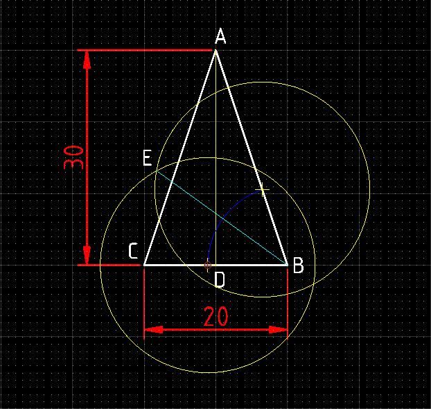
                                      Here's bisecting done with a compass:

                                      tricircbisect.jpg

                                      Steps:

                                      1. Drop the vertical line AD
                                      2. Draw an arc from the corner ABC that crosses AD (in Blue on Diagram)
                                      3. Draw two circles from the each end of the blue arc where it meets AB and BC (Yellow on Diagram)
                                      4. Draw a line from B to the intersection of the yellow circles. (Light Blue on diagram) This line bisects the angle ABC, and where it crosses AD is the centre of the biggest circle that will fit inside the triangle.

                                      Comment – problem looks easy, but has hidden depths! More to technical drawing than CAD buttons or pencil and paper, but CAD hides a lot of underlying complexity.

                                      Dave


                                      Edited By SillyOldDuffer on 02/07/2020 12:33:57

                                      #483501
                                      Spurry
                                      Participant
                                        @spurry

                                        That's sneaky, stating that a ruler could be used, after posing the question. wink The answer was simple in Turbocad, but I could not work out how to measure a 14.42 diameter circle with a compass.

                                        Pete

                                        #483502
                                        Former Member
                                        Participant
                                          @formermember32069

                                          [This posting has been removed]

                                          #483512
                                          Gary Wooding
                                          Participant
                                            @garywooding25363

                                            Sorry Barrie,

                                            I don't see how that works.

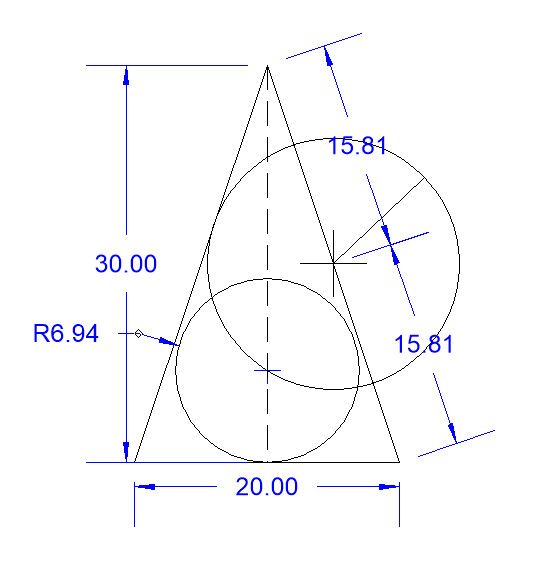
                                            I tried it in CAD and the final circle, whilst tangent to the base, doesn't touch the other two sides.

                                            me cad2.jpg

                                            #483517
                                            SillyOldDuffer
                                            Moderator
                                              @sillyoldduffer
                                              Posted by Spurry on 02/07/2020 12:54:05:

                                              That's sneaky, stating that a ruler could be used, after posing the question. wink The answer was simple in Turbocad, but I could not work out how to measure a 14.42 diameter circle with a compass.

                                              Pete

                                              Yeah, sorry about that! My bad entirely – I'm in the dog-house again!

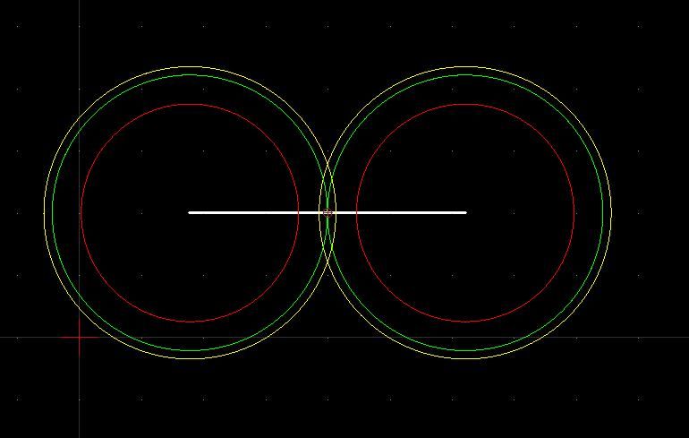
                                              Going back to first principles again, a compass can determine linear distance by using it as a divider or a doubler. Quite easy to halve a line by setting a compass until the intersections it draws match exactly, and dividing can be repeated until the human eye can't cope.

                                              dividing.jpg

                                              The two red circles are obviously too small, and the two yellow circles equally obviously overlap. The two green circles are either spot on or pretty close.

                                              Good eyesight can divide an inch down to 1/128ths, and dividing from another line at an angle to the target amplifies results allowing even finer graduations. Most struggle to read a 1/64" scale in practice. These days 1/32" is as good as this poor old duffer can do without a magnifying glass.

                                              Dividing scales by factors of two is useful, but decimal scales are even better. Another drawing challenge is how to divide by 5 with a compass to make a decimal scale, and then a vernier? At this rate, engraving micrometers tomorrow!

                                              Dave

                                              #483520
                                              IanT
                                              Participant
                                                @iant

                                                That seems a bit complicated to me SoD.

                                                I'd just draw two circles the same (but overlapping) size and then draw a line between their intersection points. That would give me the exact mid-point I'm sure.

                                                IanT


                                                Edited By IanT on 02/07/2020 14:49:48

                                                #483521
                                                Former Member
                                                Participant
                                                  @formermember32069

                                                  [This posting has been removed]

                                                  #483522
                                                  duncan webster 1
                                                  Participant
                                                    @duncanwebster1

                                                    SOD's divide by 5 problem:

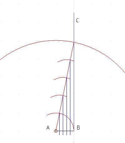
                                                    Draw a horizontal line AB 1 unit long. Erect a perpendicular from the right hand B.

                                                    Draw another line 5 units long by repeatedly stepping your compass. The set the compass to the length of this new line (5 units). Stick the point into A and swing an arc crossing the perpendicular through B at point C.

                                                    Then reset your compass to AB ( 1 unit) and mark off the diagonal line into 5 sections. Drop a perpendicular from each of these new points to AB and you've done it.


                                                    All sounds a bit long winded, but it can be a useful way of making an odd scale ruler.


                                                    Edited By duncan webster on 02/07/2020 14:53:24

                                                    #483527
                                                    SillyOldDuffer
                                                    Moderator
                                                      @sillyoldduffer
                                                      Posted by IanT on 02/07/2020 14:46:02:

                                                      That seems a bit complicated to me SoD.

                                                      I'd just draw two circles the same (but overlapping) size and then draw a line between their intersection points. That would give me the exact mid-point I'm sure.

                                                      IanT

                                                      You're right Ian, easier to do AND it would be more accurate! blush

                                                      Meanwhile, following Duncan's divide by 5 instructions:

                                                      fifths.jpg

                                                      You chaps are all too good at this…

                                                      Dave

                                                    Viewing 25 posts - 26 through 50 (of 146 total)
                                                    • Please log in to reply to this topic. Registering is free and easy using the links on the menu at the top of this page.

                                                    Advert

                                                    Latest Replies

                                                    Viewing 25 topics - 1 through 25 (of 25 total)
                                                    Viewing 25 topics - 1 through 25 (of 25 total)

                                                    View full reply list.

                                                    Advert

                                                    Newsletter Sign-up