Offset for crankshaft big ends in 3 jaw chuck

Advert

Offset for crankshaft big ends in 3 jaw chuck

Home Forums Workshop Techniques Offset for crankshaft big ends in 3 jaw chuck

Viewing 7 posts - 1 through 7 (of 7 total)
  • Author
    Posts
  • #625592
    Richard B
    Participant
      @richardb44403

      I'm part way through building a Stuart Compound engine and need to machine the big ends on the crankshaft.

      I have built a few Stuart 10v's and a Double Ten using the fixture in Andew Smiths book which is a simple steel bar end with the crankshaft main bearings offset by the stroke, thereby putting the big ends on lathe centre. This was made by a relation who had access to a jig borer.

      I know its possible with a 4 jaw to offest my DTI's only go to 10mm at best.


      So my question is what the packing required to one jaw to achieve the 7/16" stroke. The bar is 40mm dia mild steel

      I have in the past seen mentions of a web page that can accurately calculate it (can't find it now) as I understand the 1.5 x offset is not accurate and I have seen a Tubal Cain version – is sufficiently accurate ?


      Thanks Richard.

      Edited By Richard B on 20/12/2022 22:54:11

      Advert
      #16414
      Richard B
      Participant
        @richardb44403

        3 Jaw offset packing

        #625596
        Hopper
        Participant
          @hopper

          You can measure longer offset with a shorter DTI by mounting the DTI to the cross slide. Set it to zero at the low point on the job, then wind the cross slide out by the amount of offset desired. When you rotate the job, if the offset is correct, the DTI should read zero at the high point. Any reading other than that is a measurement of the amount of error you have.

          I would use the four jaw to get the desired offset dialed in by this method.

          #625602
          JasonB
          Moderator
            @jasonb

            Mark the offsets in the end of your 40mm bar and set them to run with zero movement or as close to that as you can get.in the 4-jaw

            By doing it that way you can also ensure that the two cranks 90degrees apart, something you can't easily ensure with packing a 3-jaw.


            Better still would be to mark & drill the ctr positions of the two crank pins and the crankshaft and then turn between ctrs

            Edited By JasonB on 21/12/2022 06:59:32

            #625604
            DC31k
            Participant
              @dc31k
              Posted by Richard B on 20/12/2022 22:48:26:

              I have in the past seen mentions of a web page that can accurately calculate it (can't find it now)

              The program is 'ECCENT' by Marv Klotz:

              https://www.myvirtualnetwork.com/mklotz/

              #626326
              Nigel Graham 2
              Participant
                @nigelgraham2

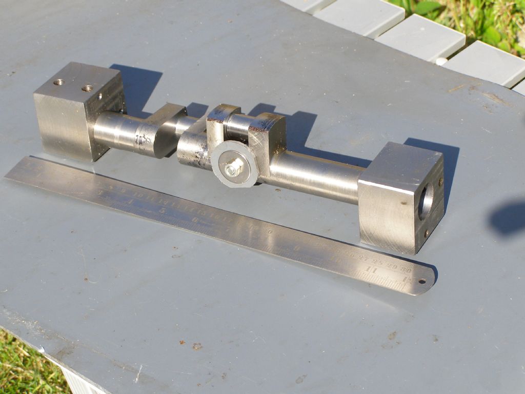
                I turned my steam-wagon's one-piece, twin, one-inch throw (two-inch stroke) crankshaft by holding it between centres drilled on the milling-machine, in square steel blocks.

                These were gripped to the shaft ends by several grub-screws each (on diameters still oversize so not damaging finished surfaces.). This lot was assembled on the milling-machine table as surface-plate, taking care to match the blocks' datum-surfaces.

                I'd considered drilling the centres on large diameters left on the shaft ends but could not see how to match them angularly, end-for-end. I now realise I could have used the web surfaces themselves, but anyway the shaft's length was against doing that, by exceeding the milling-machine's headroom

                (Photo below, temporarily re-assembled loosely for the picture without spotting I put the right-hand block back on, 90º  out of kilter!)

                The "drive dogs" were pins or blocks screwed to the faceplate surrounding the live centre itself.

                The bits between the webs are to prevent closing by tailstock pressure.

                crank-pins turned 2.jpg

                Edited By Nigel Graham 2 on 27/12/2022 13:22:18

                #626358
                Les Riley
                Participant
                  @lesriley75593

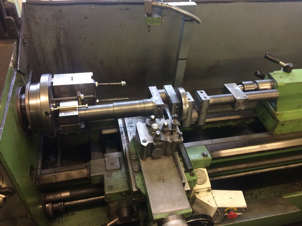
                  Both my traction engine cranks have been done similar to Nigel's above. My blocks were clamped differently but same result.

                  Note also the balance weights to smooth out the offset motion.

                  img_1376.jpg

                Viewing 7 posts - 1 through 7 (of 7 total)
                • Please log in to reply to this topic. Registering is free and easy using the links on the menu at the top of this page.

                Advert

                Latest Replies

                Home Forums Workshop Techniques Topics

                Viewing 25 topics - 1 through 25 (of 25 total)
                Viewing 25 topics - 1 through 25 (of 25 total)

                View full reply list.

                Advert

                Newsletter Sign-up