Novice beginner

Advert

Novice beginner

Home Forums Traction engines Novice beginner

Viewing 25 posts - 26 through 50 (of 108 total)
  • Author
    Posts
  • #45846
    Trevorh
    Participant
      @trevorh
      The Drawings have now arrived, Good God, This is going to be quite a task.
       
      I think I need to start with a list of the parts for the front end, why do I need the mdf disks?
       
      Sorry about this but there’s going to be a hell of lot of questions asked hoping to draw on all of the expertise out there
       
      cheers
      Advert
      #45849
      JasonB
      Moderator
        @jasonb
        You don’t actually need discs. You just need a flat platform like a bit of MDF or off cut of worktop. You then fit a pin to hold the hub and clamp the rim concentric to this as you build up the wheels.
         
        I would suggest you ask Santa for a good book on building traction engines that will show you the different ways to tackle the various parts be it wheel building, machining the cylinder, forming the tender etc. I think the best one is Edward Georges you can get details from his site and Dave’s books are quite good as well.
         
        It wil also help to look through some peoples build diaries such as Conrad’s on his 4″ Burrell and there are several builds being documented on Traction Talk forum in the model engines section.
         
        Most people seem to start with the front end as its a reasonable way to ease yourself into a project.
         
        And don’t be affraid to ask anything.
         
        Jason
        #45853
        mgj
        Participant
          @mgj
          I like discs – again cats and skins. Just easy to position rims concentrically. But yes a drawn circle on a flat board will do.
           
          No Kerbtrawler, it ISN’T a big job. Its lots of little ones, and each one is no different from the many little ones you have tackled on other jobs – except perhaps the tinbashing.
           
          Kick off with a few odds and sods that go inside the smokebox and the smokebox door, which is all pretty simple stuff.
           
          Don’t be fazed by loadsa sheets. Just pick on a bit and make it, and then move onto the next.
           
          Its also a good move I found, being a novice at TEs, to take a look at the finished version of yours. Because then you know where bits fit and what engineering “style” suits.

          Edited By meyrick griffith-jones on 03/12/2009 18:10:38

          #45866
          Trevorh
          Participant
            @trevorh
            Sound advice, Will be going to the exhibition at sandown and looking closely at any engines that are there
            Even better I now have the perfect excuse to stock up on tools and materials
             
            Cheers
            #47607
            Trevorh
            Participant
              @trevorh
              Just to update
              I purchased the drawings for a 3″ Burrell and have ordered the front wheels, Once they arrive, should be next week or the one after I can get started on the build
               
              I am going to hopefully keep a diary along with Photo’s of how I get along
               
              cheers 
              #48412
              Trevorh
              Participant
                @trevorh
                Update time,
                I have now recieved the first couple of castings for the front wheels, including the wheels and spokes,
                My first problem to overcome is how to hold the hub casting in the lathe, Finally managed to get it fairly true and machined it to comply to the drawing measurements, next issue is how to machine the recess for the spokes……
                Worked out that each are 36 degree’s apart and on opposing sides of the Hub… Got to make sure I get them the right way round.
                Also worked out that each of the internal spokes needs a 17 degree crank in order to get the crank to sit flush to the inner rim of the wheel… only 19 more to go
                 
                This is proving to be quite a challenge, working in imperial again
                 
                I have taken Photo’s of each step just for the record
                 
                cheers
                #48418
                mgj
                Participant
                  @mgj
                  Glad its coming along.  it gets easier – not the jobs but the mental approach based on experience gained!!!!!!
                   
                  Cant beat proper units  – they are just so much easier to work with than these metric jobs. If you only have metric dials – buy a DRO. They make it really really easy.
                   
                  One point – and I haven’t seen the Burrell drawings. Things that fit like pistons, cylinders axles all need clearances, and most drawings don’t specify what the clearance should be.
                   
                  I use the definitions give in the Model Engineers Handbook under fits.  Precision running. clearance etc. I used them, and you do get what kind of fit you actually wanted. I find that helps come assembly time!!!
                  #48430
                  Trevorh
                  Participant
                    @trevorh
                    That’s a good point, When I worked in heavy engineering we use to go by the rule of thumb
                    0.001″ per 1″shaft dia
                    and generaly it worked but I guess I will need to consult the old limits and fits table
                     
                     
                    #48437
                    JasonB
                    Moderator
                      @jasonb
                      Good to hear you have made a start.
                       
                      Its usual practice to mount the rim & hub in a jig and then bend the spokes to suit as the angle will vary slightly depending on what radius you allow on teh bend and how far from the hub/palm you make the bends.
                       
                      Jason

                      Edited By JasonB on 09/02/2010 18:53:57

                      #48463
                      Trevorh
                      Participant
                        @trevorh
                        Hi Jason,
                        Thats one area that I am messing around with because the drawings show the base of the Spoke should be 5/8″ but the spokes supplied are only 3/8″ which means that they can’t sit in against the bottom of the rim.
                        If i fit them as per the drawing then the radius is covered by the rim and cosmetically looks wrong
                         
                        Also I assume that I need to first dress the casting of the wheels on all faces, that is why I have provisonally bent/set only 1 of the spokes taking the angle/ offset from the drawing.
                        #48482
                        Trevorh
                        Participant
                          @trevorh
                          Another question, I keep hearing and seeing on various parts of the web the use of Adhesives used to secure the spokes to the Hub – surely they are secured with csk screws and not just relying on the adhesive???
                           
                          Can anyone shed any light on this for me
                           
                          cheers
                          #48486
                          JasonB
                          Moderator
                            @jasonb
                            The adhesive is used in addition to the csk screws, just stops any slight movement. Something like a slow setting Araldite will do.
                             
                            The palm of the spoke does not usually touch the inside face of the rim due to the fillet on the casting or welded joint. I’ll look at a few engines and get back to you re what should be right. And the boys on TT will also help, seen you have been there.
                             
                            Jason
                            #48494
                            JasonB
                            Moderator
                              @jasonb
                              I,ve just had a look through all the old 3″ Burrells on SRS and they all seem to have perfectly sizes front spokes. Without seeing the drawing its a bit hards to say whats wrong, Have a look through The pictures for yourself and see how the Tee is proportioned to the spoke thickness as this may indicate that the 5/8 dim is wrong.
                               
                              The 3/8″ does sound a bit small for a 3″ engine, the palms of the front spokes on my 2″ Fowler are 3/8, even allowing for the fact the Burrell is a smaller prototype I would have thought they would be bigger
                               
                              Jason
                              #48497
                              Trevorh
                              Participant
                                @trevorh
                                Much appreciated Jason
                                 
                                cheers
                                #49005
                                Trevorh
                                Participant
                                  @trevorh
                                  Morning all,
                                  Just an update as to where I have got to, Still machining the front hubs and after serveral attempts I finally managed to transpose the centre line from one face of the hub over to the opposite side, then off set it by 36 degree to give the alternate position of the spokes.
                                  non of which would have been possible without my rotating table….
                                   
                                   Still waiting to hear back from Plastow on the dimensions of the spokes, also the front wheel castings appear to be 1/8″ undersize on the width where the Tyre will fit, not too concerned at the moment, But I really need to know about the spokes or this will start to hold me up.
                                  Now that I am machining the 2nd hub I have mounted it in a 4 jaw chuck – this works much better than a 3 jaw


                                  Edited By kerbtrawler on 22/02/2010 11:00:58

                                  #49259
                                  Trevorh
                                  Participant
                                    @trevorh
                                    Ok , in this mornings post were a complete replacement set of Spokes.. looks as though there was an error when they were cnc’d as the new ones do indeed measure 5/8″ on the tee that will be riveted to the wheel.
                                     
                                    On measuring the width of the wheel, it is amost 1/8″ under the width shown on the drawings, will this be a problem? especially considerimng I have yet to clean the casting up, all of the other dimensions check out so it would mean that the tyre or steel band would be 1/16″ wider that the wheel. I have asked Plastows and am waiting on there come back.
                                     
                                    oh yes GOD I HATE TRYING TO MACHINE CASTINGS, this is so frustrating, BUT They do look good when finished
                                     
                                    cheers for now
                                    #49387
                                    Trevorh
                                    Participant
                                      @trevorh
                                      Hi all
                                      This weekend I will be mostly trying to master the art of Riveting – last attempted as an apprentice (hands up all who know what one of those were)
                                       
                                       Thinking back I am sure It took quite a lot of accuracy to form a good tight dome head and in the process many bruises to the hand….
                                       
                                      I have read the article on riveting here on the site but I guess I just need to have a go
                                       
                                      cheers
                                      #49726
                                      Trevorh
                                      Participant
                                        @trevorh
                                        OK I give up
                                         
                                        how do you work out the correct length the rivet needs to be to get a good shaped head on it, Is there an easy calculation?
                                         
                                        I think I need to come up with a different method of forming the head as it will be very close to the wheel casting
                                         
                                        At least I know why they sell the rivet in packs of a hundred – hammer rash not good
                                        #49728
                                        David Clark 13
                                        Participant
                                          @davidclark13
                                          Hi There
                                          1.6 to 1.7 times the diameter of the rivet protruding.
                                          That is from Model Engineering a Foundation course.
                                           
                                          I always used to make up a spacer so I could file rivets to correct length.
                                          regards David
                                          #49731
                                          JasonB
                                          Moderator
                                            @jasonb
                                            As David says its just over one and a half times the dia but varies a bit depending on your snap.
                                             
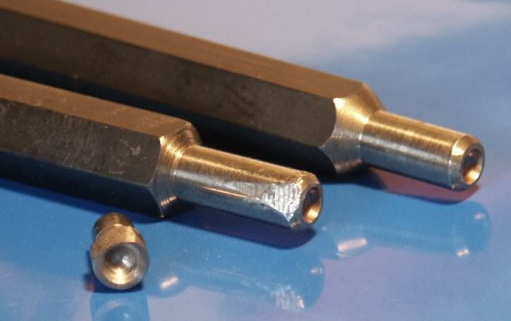
                                            I annealed the end of one of my snaps and turned the end down to a smaller parallel end then hardened again, this should help stop it fouling the rim, will take a picture later so you can see what its like.
                                             
                                            Jason
                                            #49748
                                            JasonB
                                            Moderator
                                              @jasonb
                                              This pic shows how I turned down the end of the snaps to give a parallel end as the usual tapered end meant that the body of teh snap fouled the wheel rim. You can also see on them where I have ground a flat to give even more clearance for either the radius on the inside of the tee ring web to rim joint or to clear the tie plates on teh rear wheels.


                                              You can see the usual shape of the snaps here
                                              Jason
                                               

                                              Edited By JasonB on 13/03/2010 10:20:24

                                              Edited By Katy Purvis on 01/06/2015 12:49:44

                                              #49768
                                              Trevorh
                                              Participant
                                                @trevorh
                                                Excellant,
                                                Thanks gents, That has helped a lot 
                                                I will attempt to copy the snaps shown and try again to see if i can improve on the results
                                                 
                                                cheers
                                                #50449
                                                Trevorh
                                                Participant
                                                  @trevorh
                                                  Time for an Update
                                                  Its official – I am no good at riverting, I have never known such an annoyoing process with such differing results, I need a time out
                                                   
                                                  I am going to start to machine the front axel, this at least should be quite straight forward,
                                                  I have already looked up the relevant tolerance for the 1/2″ bearing surfaces.
                                                   
                                                  I managed to scrounge some BMS 1″ bar – its a little on the large side as the main body only needs to be 3/4″ reduced to 1/2″ at each end but its free so I can’t complain too much
                                                   
                                                  Just going back to the riveting, I am going to try to use the hammer action on my drill to see if I can get a better consistancy/ repeatability
                                                   
                                                  Can some one tell me when the enjoyment factor kicks in…. 
                                                   
                                                  Cheers
                                                  #50451
                                                  JasonB
                                                  Moderator
                                                    @jasonb
                                                    Thats sometimes the best way, if its not going right then leave it for a few weeks and hopefully they will come out better next time.
                                                     
                                                    Jason
                                                    #50457
                                                    mgj
                                                    Participant
                                                      @mgj
                                                      Kerbtrawler – I love riveting.
                                                       
                                                      I started thinking it was going to be the easiest thing.
                                                       
                                                      Then I found you need 3 hands, and a spare for setting the rivet. The whole thing became an exercise in frustration. What a PITA.
                                                       
                                                      Now I have a different solution. I bought an air hammer – a scaled down version of the big air hammers the pros use!!!!. (£20 from Axminster)
                                                       
                                                      Them I turned the hammer tools that came with it rather like Jason did with his snaps. Extra – long ones in silver steel as well to get right into the bottom of the tender, but the easy ones to use are pretty short. The rivet head cavity is machined with a ball nosed slot drill to size.
                                                       
                                                      You put the “anvil” snap in a vice – making sure its supported at the bottom. You then have two hands to insert the rivet and support the job in the “anvil”. Set the rivet with a small hammer and a bit of tube. Pick up air hammer with reduced air  (40psi or so). Pull trigger.
                                                       
                                                      2 seconds later you have a perfect double domed head rivet.
                                                       
                                                      Absolutely perfick. Easy quick and painless
                                                       
                                                      Oh and don’t oversquinge the rivet or it will spread the base material. And you’ll have irretrievably curved hornplates,  and it becomes a  sod to align the crank and 2nd motion shafts. So tight, but not too tight – even the dummies around the firebox.


                                                      Edited By mgj on 06/04/2010 18:09:59

                                                    Viewing 25 posts - 26 through 50 (of 108 total)
                                                    • Please log in to reply to this topic. Registering is free and easy using the links on the menu at the top of this page.

                                                    Advert

                                                    Latest Replies

                                                    Home Forums Traction engines Topics

                                                    Viewing 25 topics - 1 through 25 (of 25 total)
                                                    Viewing 25 topics - 1 through 25 (of 25 total)

                                                    View full reply list.

                                                    Advert

                                                    Newsletter Sign-up