No 4407 More Errors

Advert

No 4407 More Errors

Home Forums Drawing Errors and Corrections No 4407 More Errors

Viewing 25 posts - 51 through 75 (of 77 total)
  • Author
    Posts
  • #71287
    JasonB
    Moderator
      @jasonb
      Hobbymat was made with 3 different spindle sizes – 55, 56 and 63mm Text and drawing would seem to be based on a 55mm machine
       
      Anyway the drawing would still be wrong as it shows 55mm into the 56mm chuck.
       
      J

      Edited By JasonB on 03/07/2011 15:59:02

      Advert
      #71289
      JasonB
      Moderator
        @jasonb
        Is it a clock making thing or is there another reason that the OD of all the gearwheels in the clock article seem to be 10-20 thou over size using (teeth +2) *MOD?
         
        Or is that why clock makers use a depthing tool rather than measure out the gear centres
         
        J

        Edited By JasonB on 03/07/2011 16:19:36

        #71291
        JasonB
        Moderator
          @jasonb
          On no I should have kept quiet about the clock. Thought I better read the text from the previous installment incase something was hidden in the text. We have , a 36tooth gear 3 times the dia of a 39T gear and again OD that are plus or minus 20thou.
           
          Seems complacancy is more predominant than pedancy
           
          J

          Edited By JasonB on 03/07/2011 17:07:08

          #71317
          ady
          Participant
            @ady
            I don’t see what the problem is.
            Everything fits together perfectly if you adapt the build as it progresses
             

            Edited By ady on 04/07/2011 04:11:39

            #71318
            Phil P
            Participant
              @philp
              Posted by JasonB on 03/07/2011 16:17:27:

              Is it a clock making thing or is there another reason that the OD of all the gearwheels in the clock article seem to be 10-20 thou over size using (teeth +2) *MOD?
               
              Or is that why clock makers use a depthing tool rather than measure out the gear centres
               
              J

              Edited By JasonB on 03/07/2011 16:19:36

              Jason

              According to the clock wheel and pinion cutting book by J.M. Wild :-
               
              For wheels the OD is (N + 2.76) x Module
               
              For pinions of 6,7 & 8 teeth the OD is (N + 1.71) x Module
               
              For pinions of 10,12 & 16 teeth the OD is (N + 1.61) x Module
               
              That is assuming the tooth form to be cycloidal as opposed to involute.
               
              Phil
               
              #71326
              JasonB
              Moderator
                @jasonb
                Thanks for that Phil, comes out OK using that formula, learn something new every day.
                 
                Jason
                #71565
                JasonB
                Moderator
                  @jasonb
                  Posted by David Clark 1 on 01/07/2011 08:52:16:

                   
                  Fig 10
                  The 2.85mm hole centerline is not shown in line with the 1.75mm recess, it is clearly shown above it. Therefore we either need a height for the hole (PROBABLY 2MM) or the 1.75mm is not the size of the notches on the bearing blocks.
                  On the original it is clearly shown in line with the 1.75 steps.
                   

                  Having just seen this engine in the flesh today at Guildford I can confirm thet the holes are above the 1.75mm step.
                   
                  The engine was running very sweetly so I would suggest to anyone thinking of making this not to be put off by these drawing issues if they can all be resolved it will build into a nice piece to add to your collection
                   
                  Jason
                   
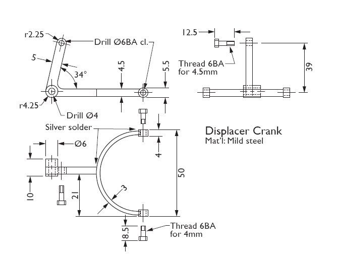
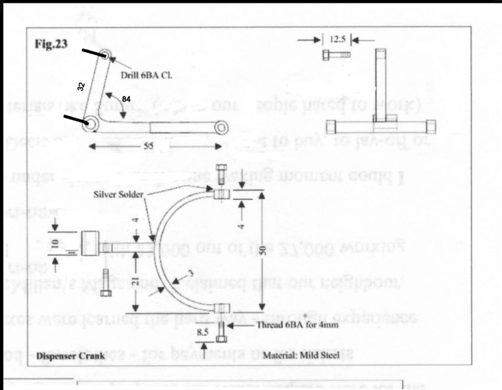
                  PS Drawings in 4408 look beter just need the angle for teh displacer crank in Fig 23 its shown as a strange 34+
                  #71569
                  David Clark 13
                  Participant
                    @davidclark13
                    Hi There
                    This is the drawing I aproved for press.
                    As you can see it clearly says 34 degrees.
                    It has obviously been changed by the page design software.
                    I will get this checked on Monday.
                    Probably to do with the fonts used.
                    regards David


                    Edited By David Clark 1 on 09/07/2011 14:44:55

                    #71570
                    JasonB
                    Moderator
                      @jasonb
                      Yes could well have scanned in 84 and got 34 out.
                       
                      Thanks, J
                      #71571
                      blowlamp
                      Participant
                        @blowlamp
                        I get that angle at 77 degrees by tracing over it.
                         
                        Martin.
                        #71573
                        JasonB
                        Moderator
                          @jasonb
                          Looks like it could also do with a dimension between the fork holes and the 4mm hole while you are at it David, as yw long teh lower arm should be without a lot of calculation
                          #71576
                          Gone Away
                          Participant
                            @goneaway

                            Is it just me or is that drawing mixing first and third-angle projections?

                            #71577
                            JasonB
                            Moderator
                              @jasonb
                              I think its you, looks OK to me.
                               
                              J
                              #71579
                              Gone Away
                              Participant
                                @goneaway
                                The boss in the corner is longer on one side than the other. In the top left view, is it longer on the side facing you or on the far side?
                                 
                                (And, if they’re consistent, are the other two views first or third angle projections?)
                                #71580
                                JasonB
                                Moderator
                                  @jasonb
                                  Longer on the far side as the photo confirms, all 3rd angle
                                  #71581
                                  Gone Away
                                  Participant
                                    @goneaway

                                    Then the lower view is wrong (or first-angle).

                                    #71582
                                    JasonB
                                    Moderator
                                      @jasonb
                                      Well the plan should really be above the two elevations for 3rd angle or if layed out as is then yes the boss should be the otherway round and the end of teh arm shown dotted effectively making it a view from below if you want 1st angle. But like I said in the other post I could make it from those drawings given the missing dimension and confirmation of the angle that I mentioned earlier which is what really matters.
                                       
                                      Also all the other drawings in 4407 use the same layout so at least they are consistant


                                      Edited By JasonB on 09/07/2011 19:03:32

                                      #71585
                                      David Clark 13
                                      Participant
                                        @davidclark13
                                        Hi There
                                        Tha angle has to be wrong or it is drawn incorrectly.
                                        I will check with Brian on Monday.
                                        regards David
                                         
                                        #71601
                                        Gone Away
                                        Participant
                                          @goneaway
                                          Posted by JasonB on 09/07/2011 18:59:22:

                                          Well the plan should really be above the two elevations for 3rd angle or if layed out as is then yes the boss should be the otherway round and the end of teh arm shown dotted effectively making it a view from below if you want 1st angle.
                                          With respect Jason, that elevation is not described as a “plan” nor is there any compulsion in any drawing standards that I’ve ever come across (formal or informal) to include any specific elevations/views. Simply that sufficient elevations/views be included to completely describe the part.
                                           
                                          In that case, and if this is indeed intended as third-angle, then the lower elevation would logically be interpreted as a view on the bottom of the view above it and the elevation to the right as a view of the right side. As such, they are inconsistent.
                                           
                                          Yes, you may be able to make the part by scrounging around for other information but any drawing should stand alone and give enough information to make the part.
                                           
                                          I sense that you don’t think this is particularly important. Dimensional errors may occur occasionally even on professionally produced drawings (particularly those that are/were manually generated) but nothing else more clearly says “amateurish” or leads to more confusion, than inconsistent projection standards.
                                          #71605
                                          blowlamp
                                          Participant
                                            @blowlamp
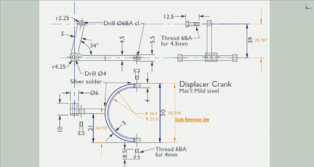
                                            As a little test, I’ve roughly scaled the drawing to the 50mm reference line and overlayed a few arcs and lines with their actual dimensions and some are pretty far out, as can be seen in the picture.
                                             
                                            The large arc is ok, but the smaller one is not so good when compared to the theoretically correct one I’ve put in.
                                            The 21mm measurement is miles out, as is the 39mm one.
                                             
                                            I know we don’t scale from the drawing, but it should bear a closer resemblance to reality than this one appears to.


                                            Martin.
                                            #71614
                                            JasonB
                                            Moderator
                                              @jasonb
                                              At the risk of these errors getting lost in another epic drawing standards thread could I ask that we keep this thread to the actual errors so its easier for future builders to locate corrections. Having said that….
                                               
                                              Sid, the use of “Plan” comes from my construction background where the view from above is generally termed the Plan View, from the side Elevations and rarely from below would be inverted plan. What I was saying is they are consistant in as much as all the drawings for this engine in both 4407 & 4408 use the same mixed projection eg 3rd angle for the elevations with what should be the 3rd angle view from above placed below the elevations rather than above. Still could be worse, the Rina has one drawing in 1st and the other in 3rd, now that is inconsistant.
                                               
                                              Martin thanks for taking the time to draw the part out and it does raise the point that without a drawing being drawn in proportion its very hard to spot if a dimension has been printed wrongly. A point for David to take up with Stavros the illustrator.
                                               
                                              Interesting that the 39mm is so far out, if it were drawn the correct length then it may mean the angle is supposed to be 84deg as I suggested rather than the 77 it measures off the drawing
                                               
                                              J

                                              Edited By JasonB on 10/07/2011 07:47:47

                                              #71619
                                              David Clark 13
                                              Participant
                                                @davidclark13
                                                Hi There
                                                The text says the centre bar is offset, so the 21 is probably correct.
                                                The drawings may not be to scale.
                                                The drawings are made from the originals and if they are not supplied to scale they will not be redrawn to scale.
                                                The same goes for projection.
                                                We have time to tidy up what we get, we don’t have time to redraw and redesign everything.
                                                If we did that, we would have to make another model to prove the dimensions.
                                                regards David
                                                 
                                                #71621
                                                Eric Cox
                                                Participant
                                                  @ericcox50497

                                                  .The 34 degree angle should be a reference dimension and the position of the 6BA clearance hole should be dimensioned relative to the X-Y axis.

                                                  Edited By Eric Cox on 10/07/2011 10:26:18

                                                  Edited By Eric Cox on 10/07/2011 10:35:49

                                                  #71624
                                                  JasonB
                                                  Moderator
                                                    @jasonb
                                                    I would have thought that the curved dimension line indicates that it should be an angular measurement.
                                                     
                                                    But agree that teh hole could be positioned using teh 39mm and a second dimension fort teh other axis.
                                                    #71689
                                                    David Clark 13
                                                    Participant
                                                      @davidclark13
                                                      Hi There
                                                      Updated dimensions.
                                                      84 is correct measured from original.
                                                      regards david

                                                    Viewing 25 posts - 51 through 75 (of 77 total)
                                                    • Please log in to reply to this topic. Registering is free and easy using the links on the menu at the top of this page.

                                                    Advert

                                                    Latest Replies

                                                    Viewing 25 topics - 1 through 25 (of 25 total)
                                                    Viewing 25 topics - 1 through 25 (of 25 total)

                                                    View full reply list.

                                                    Advert

                                                    Newsletter Sign-up