Hello there another new member from Staffordshire saying hi to all .
im new to myford lathes and part names so please be gentle with me and ive just acquired a myford ml4 that's been semi modded ie it runs from a treadmill motor so no changing belts ,at some time in its life someone added a taper bearing to the nose end of the stock .which means the the mandrel is sticking out about 1/4 inch more than normal .but my problem is the mandrel gear is missing from the other end. so I cant engage the tumble .dose anyone know where I can get one or the correct name of this gear , by what I can make out from pictures of ml4 lathes it as a collar attached to the gear and is held in place via a grub screw ? ive surfed the net but no luck .I would love someone to advise and point me in the right direction .
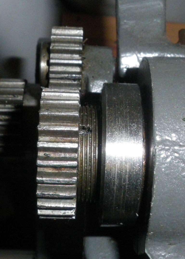
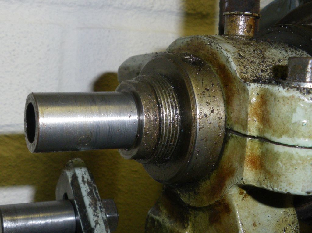
I presume from your mention of tumbler reverse that you have the later ML4. On this the 25T mandrel gear (a name I just made up) is internally threaded. It is screwed onto a fine thread at the end of the mandrel:
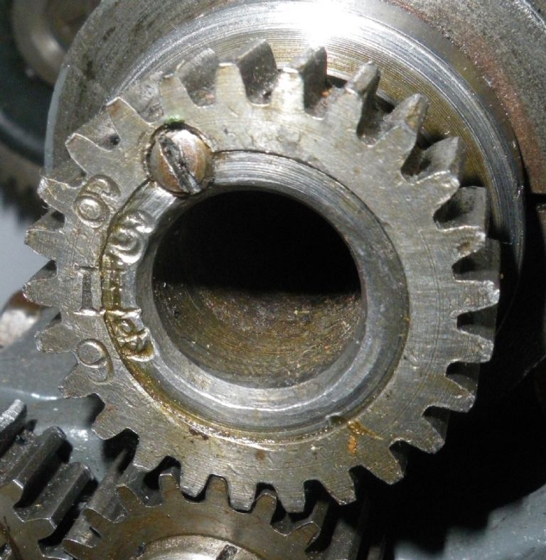
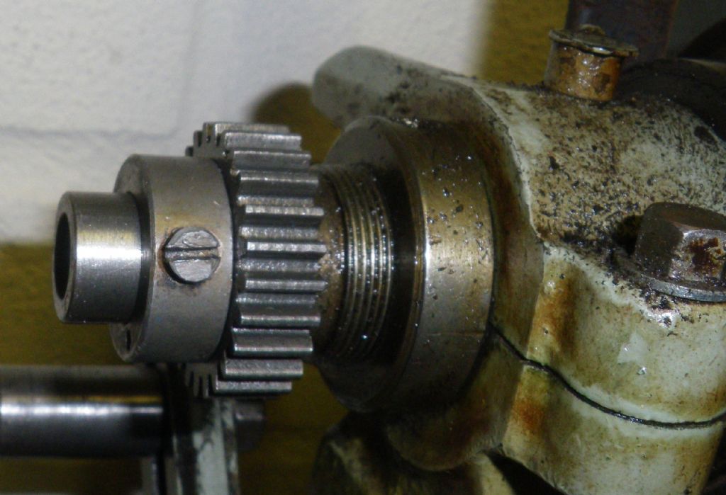
It is then held in place by a grub screw threaded axially into the joint between the gear and the mandrel:
This works well until you need to dismantle the headstock, as it is a real fiddle to get it aligned again. The gears occasionally appear on a well-known auction site, but you could wait a while to see one, and of course you would need to drill and thread anew for the grub screw (2BA at a guess). There's no technical reason why you shouldn't bore out and thread a standard 25T wheel, except that without the mandrel gear your present lathe can't be used for cutting the thread.
Incidentally, the earlier ML4 without tumbler reverse had a smaller diameter mandrel, and the mandrel gear was any suitable changewheel slid on and pinned to a drive collar in the ordinary way.
As far as your taper bearing is concerned, it sounds as though somebody has fitted (or attempted to fit) a mandrel from a ML7-R or Super 7. I have no idea how the mandrel gear from those is fitted, so it may be different from the original ML4 arrangement I have described. Perhaps the knowledgeable ones could chip in at this point? Using a 7-series mandrel would certainly give you the 1 1/4" diameter register behind the nose thread, which wasn't present on the ML4.
The extra quarter-inch overhang will reduce the rigidity of your lathe (which in any case is not great in the ML4) but I don't know how significantly.
Do keep us informed about how you solve the gear problem.
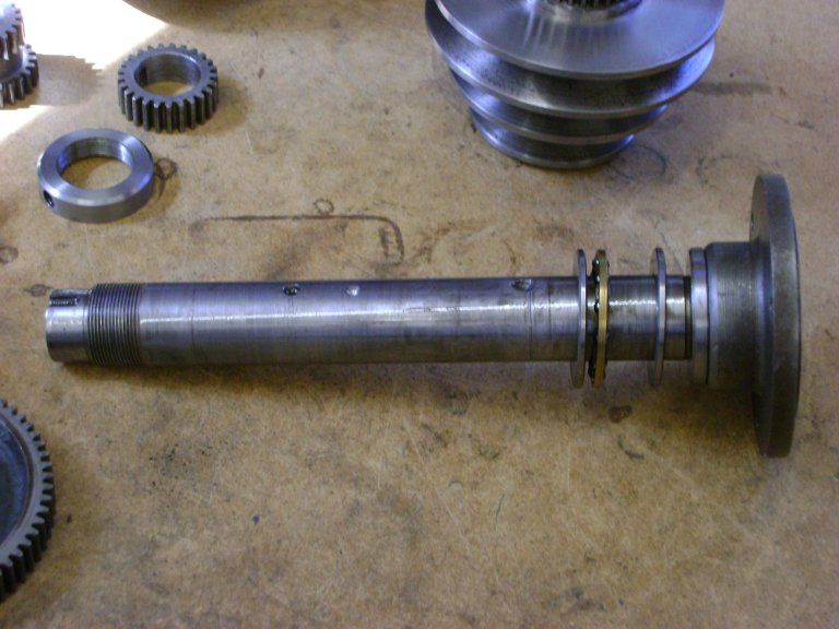
On mine the first gear in the chain on the spindle is *not* threaded. It's just a plain push fit. The grubscrew is all that holds it in place.Slightly further along the spindle, is a threaded section with a nut. This nut provides preload for the thrust race immediately behind the nose for faceplate and chuck mounting at the other end. Even though the gear has threads in the near vicinity for the preload nut, there is a smaller plain section with a shoulder against which the back of the first 25 tooth gear rests.
It must have been like this from the factory because the gear is marked with a stamped number across the divide between the gear and the spindle. If someone modified it to remove the threaded portion after the factory they couldn't have made the hole in the gear smaller, nor is it likely they would have stamped it with a number and erased the original. I can only think that they were all different, and this is not the first time I have come to this conclusion about the ML4.
I've modified many things on mine but this is not one of them. Someone else may have modified this after the factory, but I am certain that almost every one of these machines is a little diffferent anyhow. The difference between the ML2-ML4 is subtle and certainly not a precise science. Some things were clear differences, but other not so clear.
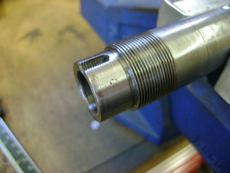
thank you for your reply and pictures to go with it ,you couldn't of explained better ,but I think my mandrel is a ml4 and I can now see that the gear thread is stripped part way towards the end and a hole drilled through one side which I guess would have been there bodge way to hold the gear on , theres enough thread left to adjust slack in the mandrel.via a small threaded collar with a grub screw .I checked again its not a taper bearing it just a narrow open case bearing .that as been tack welded to the stock housing .I will try and get a picture or two so people can get a better idea .ps today I turned an old back plate for my little burnerd 6 jaw chuck . and then clocked it at 00.1mm run out I think that's not to bad ..? so I guess the bearing is doing its job
thanks and nice looking lathe mate , im now confused is my mandrel thread stripped or is it just rough on the end of shaft ? where its been messed with ,I think mine should look like that push on and a grub screw in the end because theres signs of threaded slot ? the same kind of end gear is available for the ml7 series but the bore is bigger ,now my brains ticking over ,if I cant get a ml4 gear could I attempt to clean the mandrel end up then cut a keyway in it with a dremel then make a slotted bush to fit the ml7 gear ? maybe to much and not enough meat on the mandrel .?
guess ill have to keep looking for a mandrel and gear .
cheers wayne . and sorry George I didn't say cheers ,so cheers I cant edit post ?
I'm afraid I can't get any more pictures until Thursday. I am away from home and the machine is at the other end of the country. I'd be happy to dismantle the headstock and take some pictures then, so that you can get a better idea of what you are doing. My machine is only loosely assembled because I've not finished the refurb yet. That makes it easy to dismantle.
The only really important thing with the ML4 headstock is the main bearing adjusting screws.
* Don't over-tighten them.
The headstock has split plain bronze bearings and they are pressed into the iron headstock casting which is also split. I guess they thought that they would wear and might need adjustment. The trouble is when you tighten the bolts across the split. It's way too easy to over tighten them and then the casting breaks. You often see these machines on e-bay where the headstock has been modified (ugly) to fix this problem. If you get a chance make shims with holes for the bolts and put them in the slots. That way you can prevent over tightening. The shims could even just be washers if you can find the correct thickness.
To dismantle the headstock;
Remove the grubscrew (2BA) on the end of the spindle and then remove that 25T gear.
You can then undo the grubscrew in the screwed preload ring behind the gear; then unwind the ring and remove it.
Loosen the main bearing adjustment bolts.
The pulley and bullgear are both attached to the spindle with grubscrews. Both need to be unwound by a few turns. The ends of the grubscrews are pointed and conical seats will have been machined into the spindle. The point of the grubscrew needs to be withdrawn to clear the conical seat completely. If the point is sticking out it will feel loose but will raise a burr on the spindle when you withdraw it. The burr will in turn damage the bronze bearings when you finally withdraw the spindle. If you can just remove the screws completely it is much better.
The screw for the pulley is usually in the middle position for the belt. The screw for the bullgear goes in at a diagonal to the spindle. The screw is on the spindle nose side of the gear. If you line it up with the notch in the back of the front bearing, you'll get a screwdriver to it better.
Remove the backgear cover, so that you can support the bullgear when you withdraw the spindle.
Initially, just support the pulley with one hand wilst withdrawing the spindle with your other. When the pulley clears, remove it, then support the bullgear. Usually when the bullgear clears the spindle will be more or less free to remove anyway.
thanks again Andy taking the time to reply with what seams a straight forward removal process . ive read somewhere about over tightening the main bearings and people have used shims of hardwood . the spindle come out chuck end I guess ? . when I think back I used to work as a engine reconditioning place in oldbury west mids using all types of machines could of got new shaft and bushes made up , now im gutted hehe
This is getting interesting! Andy, your description and dismantling instructions are very clear but I would add one thing – if the previous owner hasn't successfully located the pulley grubscrew in the conical housing on the mandrel (many didn't) it is likely to have dragged the screw point all the way round and raised a ridge each side of a groove. This can make the pulley difficult to slide lengthwise and the mandrel difficult to slide out through the bearing. I have seen it happen to the bullwheel too. The only way I have found to get round this is to 'insist' as there is no way to get in and remove the ridges. It's not nice to do!
Back to the mandrel gear: Andy, your serial number looks like 871, which makes it newer than mine which is 619. It looks likely that they changed the design between them, shortening the threaded section and sliding the gear onto a plain section. It would certainly make alignment easier when replacing the gear on the shaft. Wayne, is there a serial number on yours?
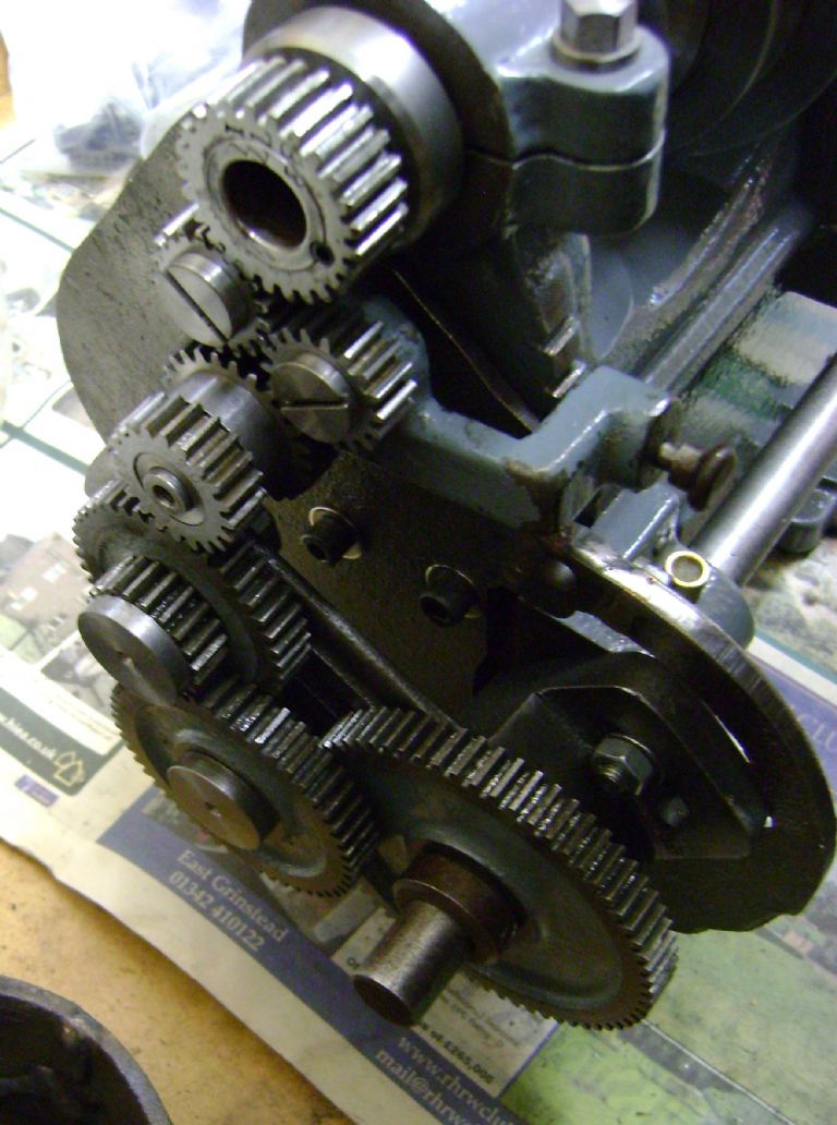
For completeness, here is the arrangement on an early (pre serial number) ML4 with no tumbler reverse and the very narrow bore mandrel with 7/8" nose thread. It has the same threaded collar arrangement for bearing adjustment, and a plain turned section outboard of that (in two diameters).
The changewheel – any changewheel – simply slides on and is pinned to a drive collar with the usual 3/32" silver steel pin. The drive collar is secured with a 1/4" BSF grubscrew. I have never had any problem with it slipping:
This is not a Myford mandrel, so the extra length to the left of the drive collar may not be to the original design.
Incidentally, the exploded view of the ML7 headstock on Myford's website shows a plain section outboard of the threaded section on the mandrel, so it seems likely they carried that arrangement over from the ML4 as both simple and satisfactory.
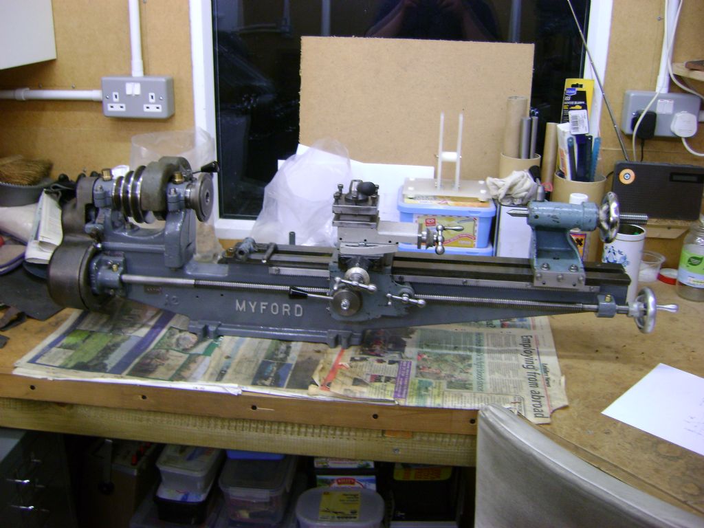
If you look at Andy's first photo and follow straight down from the back gear, there is a raised panel in the bed casting just below the leadscrew. If your lathe has letters and numbers stamped there, that's it. The early Myfords had no serial numbers (so no raised panel). I don't know when they started numbering them, and I suspect that nobody else does either.
The number was also stamped on the end of the mandrel and on the mandrel gear as you can see in my photo, and on the underside of the tailstock and often under the slides and saddle too.
just looked at mine and it as the raised casting stamped LR856 and looking at your pictures im now thinking about turning a short stepped shaft to fit inside my mandrel to fit a gear . which would line up a new 25 tooth gear with the tumbler .as my mandrel is about a 1/4 " shorter than normal so even if I did find an original gear it would be short .hope this makes sense .
You're quite right. It is a problem, it's a long time since I had to go through what you dscribe.
I've had the machine since I was eleven, and I'm now in my mid forties! Granted it spent a long time as parts in a box, but it seems to have stood the test of time. I learned to turn on that machine, I got ten years use out of it.
I'd forgotten that I had to drift the spindle out with a hardwood block and a 'mer. The bearings are original, and it is still fine, so I guess I was careful enough.
I think this stirred a braincell or two actually.
So, when you remove the spindle, it comes out through the bed end of the headstock. Also it is worth looking out for burrs raised by the grubscrew on the preload ring behind the 25T gear. Obviously that grub screw bears directly on the screw thread, and that's a little nasty. If a burr has been rised on the thread there, then it will be good if you can take the burr away with a stone, or a diamond file. The benefit is that you don't then drag the burr through the bronzes.
The same philosophy is true of the pulley grub screw that would need removing to engage the back-gear. Obviously you need to remove that to extract the spindle, but if it has not been properly withdrawn when the backgear was used, it will make a mess of the spindle, which can then damage the bronzes. I doubt you will be able to get at the damage unless you remove the spindle, but if you get the spindle out, you should certainly tidy it up with a stone.
I'm really not sure about the wisdom of the tumbler reverse anyhow. The machine should cut a right hand thread well enough, but the thrust race only copes with forces into the headstock. Any operation which requires resistance to a cutting force away from the headstock is not adequately managed by the design of the lathe. This includes turning operations away from the chuck and cutting left hand threads.
The preload ring does rest against a shoulder on the bronze headstock bearing, but there is no way it is as good as the thrust race on the nose end of the spindle. I guess it's woth being mindful of that, especially if you are a user of a vertical slide, and you use the side of a milling cutter often.
These old lathes are often quite limited, by comparison with newer machines, but you can still produce excellent work if you understand their limitations.
P.S. Mine has matching numbers on the bed, under the saddle and on the tailstock. It also has a small aluminium plate which I think indicates that it was owned by the Air Ministry. There is a number, and a small crown. There are letters around the crown, "P P" either side above, "A M" either side below the crown. I always wonder if mine actually shot down an ME109!
'Also it is worth looking out for burrs raised by the grubscrew on the preload ring behind the 25T gear. Obviously that grub screw bears directly on the screw thread, and that's a little nasty. If a burr has been rised on the thread there, then it will be good if you can take the burr away with a stone, or a diamond file. '
Funny you should mention that, Andy. There was a time when I tried to remove the ring, completely forgot to release the pointed screw, and dragged it round part of a turn before I twigged that it really wasn't right. Fortunately the point follows the path of the thread, so a few minutes with a small file put it right. The thread isn't hardened (as far as I know none of the mandrel is) so a dead smooth file will right all sorts of wrongs.
I have ordered a 25 tooth gear but its from a ML7 tumbler it s got a collar on it and I can drill and tap it to fit the shaft, it as a smaller bore size but im hoping to make a short shaft to fit one end for the gear and the other to fit inside the mandrel end hopefully this will slightly extend the gear end to line up with the original tumblers .fingers crossed .ps does anyone know the sizes of the original bronze bushes ?and the mandrel size and threads so I can make a set on this lathe before I strip it .I want to get rid of the bearing that was added to the chuck end of the headstock ..
So I posted some more pictures to my album that might help you.
The ones below are examples;
The spindle is 1" in diameter, and as best I can tell the thread on the end for the pre-load nut is 1" x 24TPI more than likely Whitworth form. The shoulder on which the gear sits is 7/8" in diameter and 1/2" deep.
The distance from the shoulder at the back of the spindle, to the collar which rests against the thrust race is 6 15/16". That is the full length of the 1" diameter part, including the part of the 1" diameter which is threaded.
The actual nose is the same thread as my Super7 but the register on the Super7 is slightly larger. I think the thread is something like 1 1/8" x 8TPI. All I know is that I can put chucks from the 7 onto the 4 but not the other way around.
I've not provided dimensions for the bronzes because I'd have to push them out to measure them. I don't want to do that.
In the end you're going to do what you will, but I wouldn't recommend making new bronzes yourself if you only have the one lathe. The bronzes need to be made with their bores under-size. Then you fit them, and line bore them to size with a "between centres" boring bar. You mount the headstock to re-manufacture on the vertical slide. This way ensures concentricity of the two bearings.
If the bearing you are to eliminate is the thrust race in the pictures I have shown, then I'd suggest that you want to keep that one. In any case if the thrust race is pitted or otherwise damaged, a decent bearing supplier will be able to get you a replacement.
If anything, the desirable change, is to machine into the back of the rear bearing mount. Obviously you would reduce the length of the rear journal, but if you make it the same as the front one, and put a thrust race in there, you can turn right and left hand threads without any problems.
I might be able to do this on my Super7 with my boring head, the same as the line boring, but I just don't feel tempted. Too little gain vs. too much risk of error. You might be able to find someone else that could do this for you. Many of these things are possible on smaller machines, but they become reliable and procedural "small jobs" on bigger machines, like a Bridgeport or a K&T.
thank you so much for taking the time to go through trouble of pictures and description it will help a lot in my new adventure , after 30 years since I used a lathe .must be a late mid life crisis ,haha I may look for another headstock ,ps .could you measure the length of the bushes without removing them please so I have a rough guide .
I don't mean t be funny, but you're going to need to measure the inside diameter of the headstock casting to make new bronzes with the right kind of fit. The only casting in the world that you can make that measurement on, is yours.
To make that measurement you're going to have to take it apart. Once you do, you can measure the length of your own anyway. I put mine back together now, and I'm not taking it apart again. I'm not that helpful.
In consolation, the vee pulley in my album pictures apparently came from another ML4. When I assembled it, it was about 1/4" too short. I had to weld on the spacer that you saw to stop it drifting back and forth when using the back-gear. The upshot of that, is that even if I did measure the length, I have hard evidence that the distance between the bearings is different on different machines.
the new 25 tooth ml7 tumble gear came today so ive been in the shed all day .and my plan was a success .
first I made a short 3 inch shaft one end 1.3/4 long to fit the bore in the ML4 mandrel which I drilled a 3mm hole in tapped and grub screw to hold it in the mandrel I hade to bore a 1/4 inch deep into the back of the tumbler gear so it just sits on the end of the mandrel . and I then turned the (1.1/4) length of the shaft ,to fit the ML7 tumbler , I used the oil hole in the tumbler gear to tap and put a grub screw in to pinch up on the short shaft .it all lines up with the change wheels now ,and the lead screw now works ,and quite smooth ,it don't sound like a load of nuts and bolt going around in a washing machine the ML7 tumbler as a small collar then a short section that as a w.key,and I can use a ML7 gear if needed and that also lines up with the outer gears , it was a lot of messing about due to the lathe not cutting straight .the cross slide and saddle need setting up it cuts tapered so ive had to allow for this and do light cuts on the thick end of the shaft to take the taper out then use a file to and marker pen to true it up , .ive never set a lathe alignment up before but I guess some one will tell me how to align everything , I hope . I will get a few pictures up as soon as im fully happy with mod . the way its been done its not damaged anything if I ever get original bushes sorted .and remove the front added on bearing because I would then get back the full length of the mandrel .the only thing I have lost by modding is i will be limited on how long the bore of the mandrel is , see how it goes at least the lead screw is functional now ,once ive sorted the issues and im happy I will then strip it and paint it .
thanks to anyone who helped me with info a most of all pictures .