New To CAD? No, but….
New To CAD? No, but….
Home › Forums › CAD – Technical drawing & design › New To CAD? No, but….
- This topic has 156 replies, 25 voices, and was last updated 28 May 2022 at 13:09 by
blowlamp.
-
AuthorPosts
-
11 May 2022 at 07:07 #597791
 JasonBModerator@jasonb
The video I did some time back of your cylinder "casting" is a good example of what Nealeb says about sketching a rough shape and then constraining it by setting lengths and positions which is also how I tend to work. At the start you can see I draw a basic rectangle then constrain it's size and then it's position relative to two axis/planes which makes subsequent mirroring possible.
Your TC Deluxe is not the top of the range and being 3 years old now is still mostly 2D based, many of the images you see on the TC forum may well be pro versions and on the latest version.11 May 2022 at 07:22 #597793David Jupp
Participant@davidjupp51506Nigel – be careful using STL files to transfer designs between systems.
STL is not a CAD format, but was developed for 3D printing. It represents the design as many triangular facets, so it ends up being 'not quite' what was originally modelled. Some precision will be lost, and many CAD systems can't usefully edit STL.
If available STEP (or STP) , IGES, or others should give more robust results.
11 May 2022 at 09:30 #597811Nigel Graham 2
Participant@nigelgraham2I can understand why printed tutorials for particular makes of CAD are rare or non-existent, but there is a paucity of even the more generic ones. I own copies of the only two I have encountered, both written for model-engineers – one at least by a model-engineer too, D.A.G. Brown, but quite some years ago.
Ah, so Constraints are not quite what they are cracked up to be? Well, I can't judge that as I've not advanced that far.
I am grateful to PatJ for explaining what Paremetric modelling is. Though again beyond my present level and probable need (advanced CAD systems are intended for industry after all), at least it avoids confusing me I can see it value when designing complicated machines or system intensively – as in industry.
I see your (Pat's) point about Planes. I suppose the TurboCAD parallel is that of placing the work-plane, by default the "floor", on any facet or section of the object being drawn; but its work-plane system can lead you into all sorts of difficulties.
David –
Thank you for that tip. I did wonder, because the TurboCAD file-type list helpfully says what the abbreviation means: in this case "Stereo Lithography". That suggests it was originally designed for map-making.
What you say about it also suggests why my cross-head became mis-aligned. I am pretty sure I had verified the item's axial alignment when I added the spigot to the body.
.
Having found a way, if not the best way, to transfer the file I spent a while just exploring SolidEdge to get some feel of how it works.
I succeeded after some experimenting, in drawing a rectangular block, drilled two holes through it then gained some idea of how the dimensions work.
I like the way they are active – controlling the object itself. Before I twigged that I was baffled by no obvious way to locate a feature across a surface.
In TC, dimensions "associated" with the object follow changes to it, but they are still otherwise passive. I think I've found how to define the dimensions themselves in SE to give datum points – after I spotted that trying to move the holes altered the size of the block itself. The holes' locations were leading the size of the "metal" around them, though I am not really clear how.
With TC's 3D in similarly symmetrical objects I glue a little sphere to the leading corner, to help me orientate myself to the object when seeing it from a different direction; and to give it a home position. (I have found the "home" control on SE, next to the view-direction control, that does much the same thing.)
My best bet if I want to make any progress with SE might be similar informal exercises, but in 2D first so simpler. My usual approach – developed with TurboCAD – is to create a couple of very simple shapes and play around with them.
It might be worth me writing notes as I go so I build up my own "operating manual".
11 May 2022 at 10:15 #597817SillyOldDuffer
Moderator@sillyolddufferPosted by Nigel Graham 2 on 11/05/2022 09:30:01:
…
Having found a way, if not the best way, to transfer the file I spent a while just exploring SolidEdge to get some feel of how it works.
…
Word of warning – transferring files between CAD packages is an advanced topic. A beginner might get lucky, but unskilled imports usually have peculiar consequences. For example, even if the correct file format is selected, and both packages understand the dialect equally well, a faulty model imported from TurboCAD will thoroughly confuse Solid Edge. Import/Export is a good way of creating problems that baffle experts.
Better to save import/export for later. Get Solid Edge working from scratch and understand the basics before attempting anything complicated. No good tackling locomotives before you can do a Cotton Reel! Same is true of learning any CAD package – they all depend on a reasonable understanding of the basics.
Dave
11 May 2022 at 10:50 #597824Nick Wheeler
Participant@nickwheelerPosted by Nigel Graham 2 on 11/05/2022 09:30:01:I can understand why printed tutorials for particular makes of CAD are rare or non-existent, but there is a paucity of even the more generic ones. I own copies of the only two I have encountered, both written for model-engineers – one at least by a model-engineer too, D.A.G. Brown, but quite some years ago.
Ah, so Constraints are not quite what they are cracked up to be? Well, I can't judge that as I've not advanced that far.
My best bet if I want to make any progress with SE might be similar informal exercises, but in 2D first so simpler. My usual approach – developed with TurboCAD – is to create a couple of very simple shapes and play around with them.
It might be worth me writing notes as I go so I build up my own "operating manual".
In order:
DAG Brown's book is hugely out of date for 2D CAD, and largely irrelevant for 3D. Referencing it is reinforcing your misunderstanding of the different requirements for 3D. Put it on a shelf where you can't see it, and won't be tempted to read it again. Mine is in numerical order with other Workshop Practice Books; I haven't opened it in ages.
As you've discovered, it's very easy to draw figures that look connected, parallel or whatever, but aren't. That doesn't matter (much) on paper, but it's deadly in CAD. Constraints are used to ensure the geometry you've drawn is and remains what you want, as their names demonstrate: perpendicular, concentric, symmetrical, parallel, colinear, coincident, mid point etc etc. They're vital, and are normally used before dimensions.
Informal exercises are important, but inventing your own will lead you down frustrating paths. Try simple parts that you already understand. A T-nut, simple split clamp then a U-bolt would be a good start for many of the processes. There are several ways of creating these, as a few minutes in front of the computer for each will prove. Some are much better than others even though the end part will be identical.
11 May 2022 at 11:08 #597826Nigel Graham 2
Participant@nigelgraham2Dave,Nicholas –
Thank you for that advice.
I had assumed transferring a file from one type of software to another might lead to details like some of the formatting being lost, but I'd not realised it's much more than just the data.
Ah. I'd not known that "constraints" include those controls I'd already been using under their own names! Normally I would expect to add the dimensions afterwards, and TC certainly works that way. SE perhaps does too but in a different way, as the little menu-video I found on auto-dimensioning shows.
When I invent an exercise I do keep it as simple as possible, often not even depicting an object like a T-nut, just two or three basic shapes.
Mr. Brown's book looks out-of-date even from its cover photo – but I don't think it covers 3D at all.
11 May 2022 at 11:34 #597830Nick Wheeler
Participant@nickwheelerDepending on how you model it, a T-nut is only two or three basic shapes. But it's useful as an exercise because you know what it ought to look like and understand what each shape does. That also explains why these two approaches are both better for different reasons:
Each identical solid is created from a simple sketch using two operations and the thread added by a third. The bottom is good for a discreet part; the top makes more sense when it's a part of an assembly
11 May 2022 at 12:09 #597835Anonymous
There seem to be some complicated ways of looking at, and creating, parts being mooted?
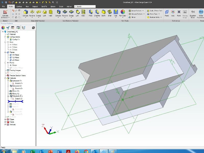
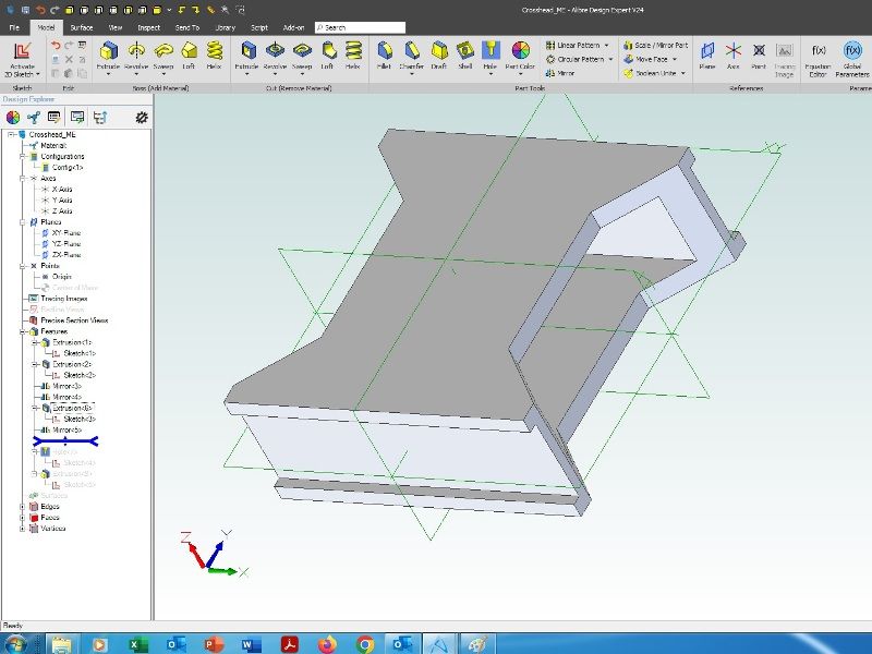
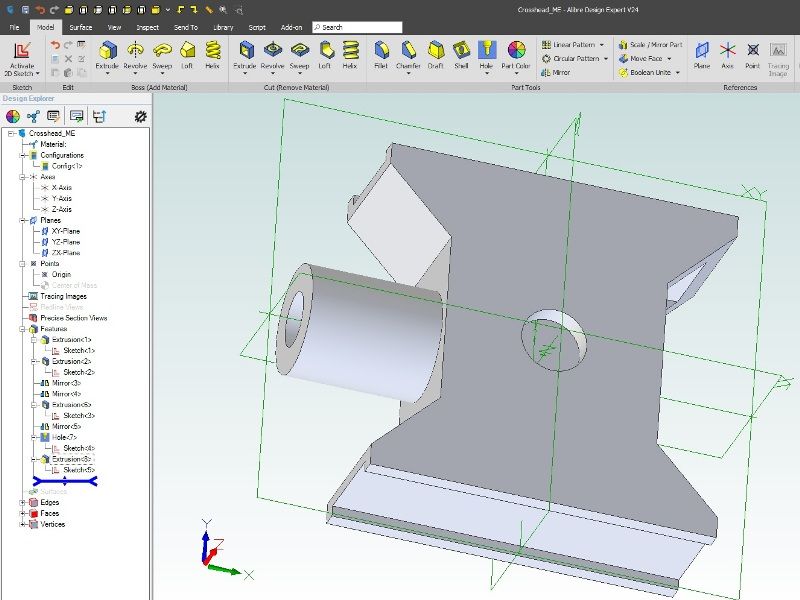
Considering the crosshead shown earlier one notes that it is has partial symmetry in 3 directions. So I would model it as followings:
Draw 1/8 of the crosshead body. Extrude cut the slot for the slidebar and for the cutout for the connecting rod.
Mirror everything preceding in one plane
Mirror everything preceding in another plane
Mirror everything preceding in the third plane
Add hole for small end pin
Extrude boss for the piston rod – if the hole is flat bottomed it can be extruded as a tube, if drilled extrude a cylinder and add a drilled hole
To my mind a T-nut is one indivisible part with one shape. I'm not sure where an assembly comes into it? I'd make the t-nut by extruding the shape of half the t-nut, then mirror and finally add a hole with appropriate thread.
The advantage of using mirrors is that if changes are needed then only one domension needs to be changed. Of course for multiple dimensions that are always the same the subsidiary dimensions can be pointed to the original dimension and will update automatically. That does mean that you have to remember which dimension was the original.
In my 3D CAD program (Alibre) there are two different areas where constraints apply. One, in sketches where they control features in 2D. Two, in assemblies where they control positioning of parts in 3D.
If anyone doesn't understand my part modelling descriptions above I'll implement them and post screenshots.
Andrew
11 May 2022 at 12:56 #597840Nick Wheeler
Participant@nickwheelerI'd use symmetry for the crosshead, but in one original sketch, and the extrudes:
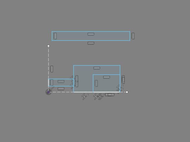
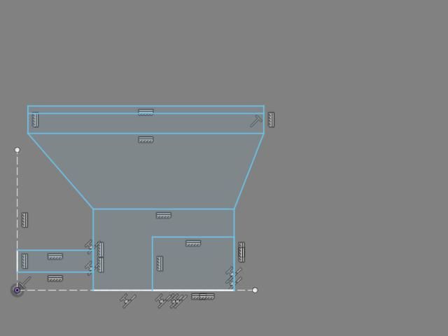
Draw some rectangles and construction lines:
add several colinear constraints for most of the profile:
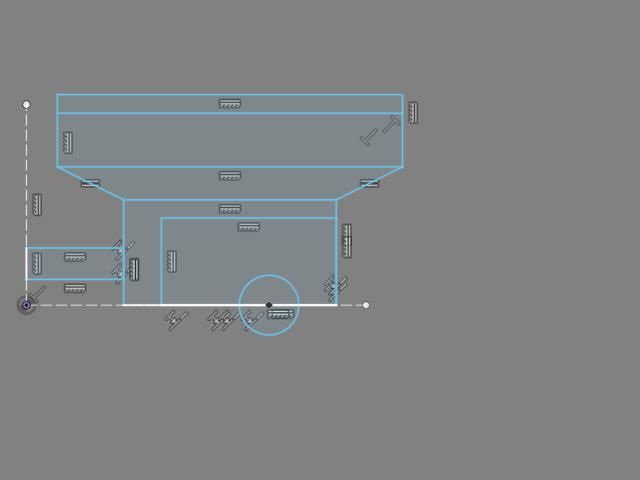
Draw 3 more single lines, then make the angles ones equal with another constraint:
Move everything about for the proportions – this is where you'd add dimensions – and the circle I forgot
Extrude most of the profiles symmetrically:
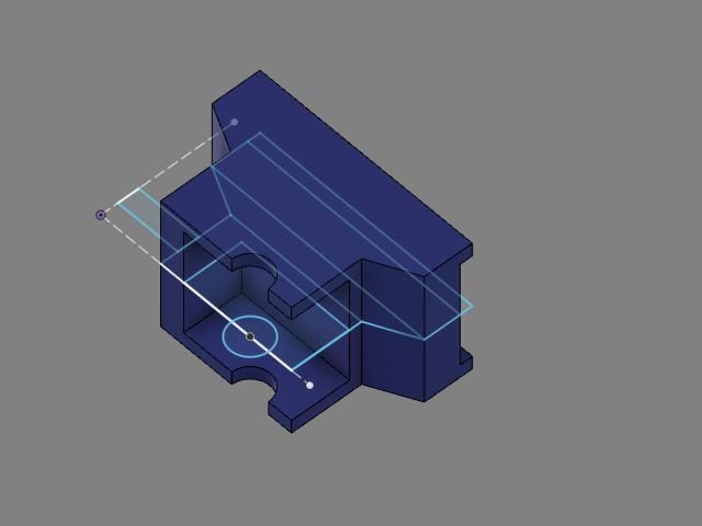
Extrude two more profiles symmetrically as a cut:
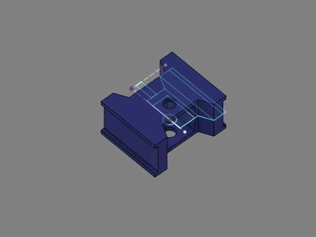
Mirror the resulting body around its own open face, ensuring that join is selected:
Finally, revolve the last unused rectangle around the construction for the hollow spigot:
That's probably as complicated a sketch as you'd want, but simplifying it would need two more for the other features. The pin would be created in place, using projected geometry from the hole it fits in.
11 May 2022 at 20:55 #597895Anonymous
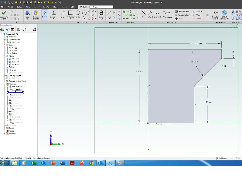
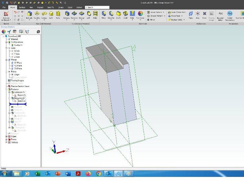
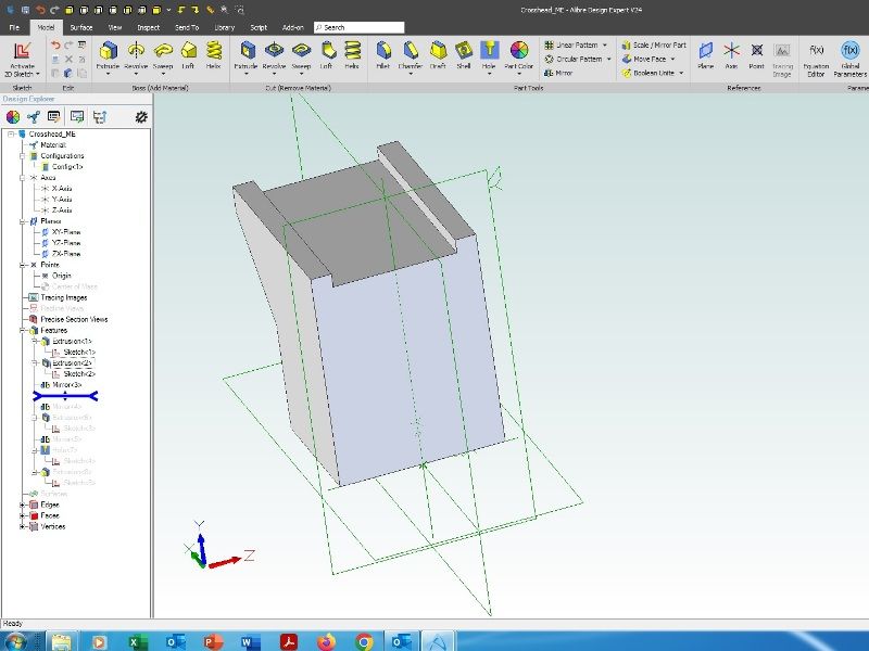
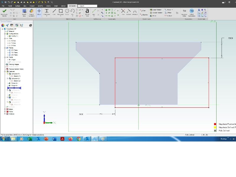
Crosshead CAD – Part 1
First sketch on the XY plane, with dimensions:
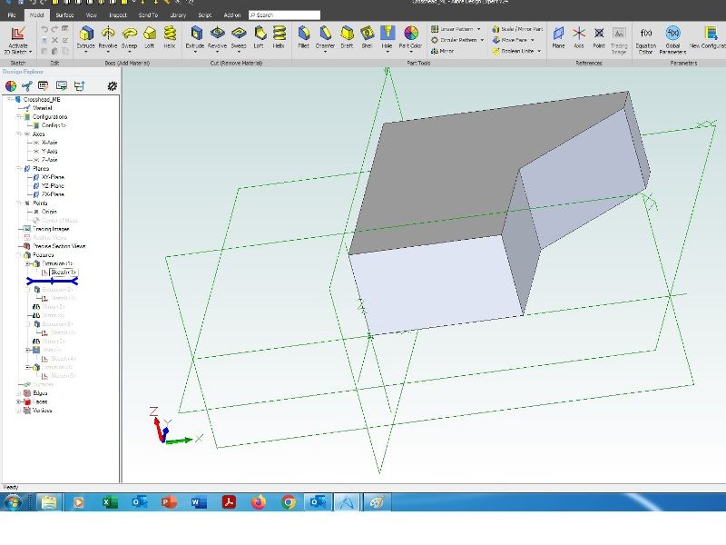
Line at bottom is constrained to be on the X-axis and on the left to be on the Y-axis. Extrude the sketch on the Z-axis:
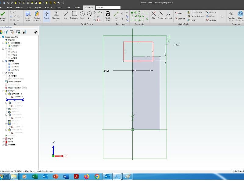
Sketch on the end face of the model for the slidebar cutout, only two dimensions needed:
Extrude cut through all:
Mirror everything in the XY plane:
Mirror everything in the YZ plane:
TBC
11 May 2022 at 21:04 #597897Anonymous
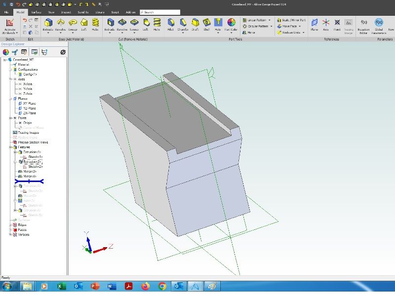
Crosshead CAD – Part 2
Sketch for the cutout for the connecting rod on the XY plane, only two dimensions needed:
Extrude cut to depth midplane, so equi-spaced around the XY plane:
Mirror everything in the ZX plane:
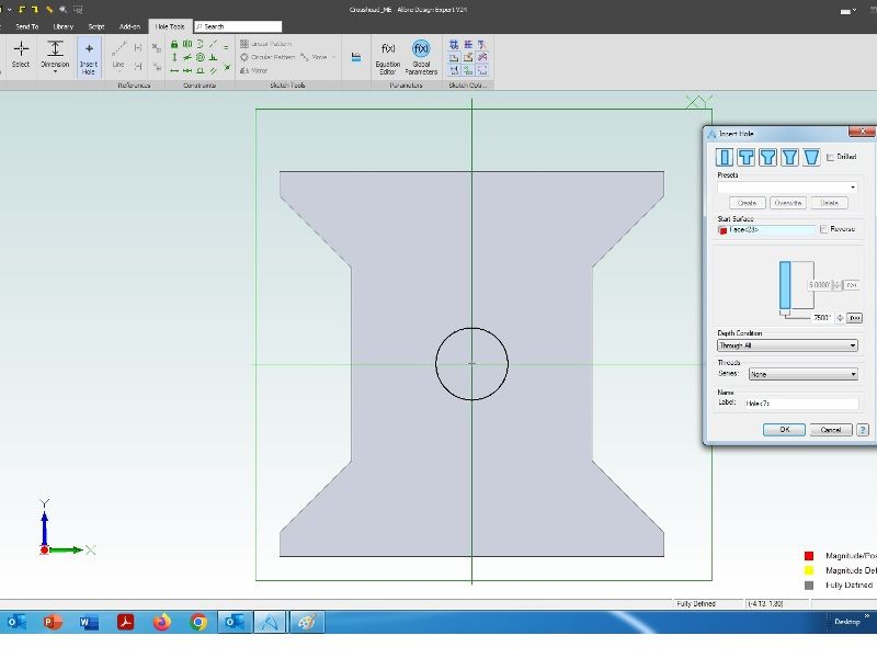
Add hole for the little end pin. Dimension of the hole is in the submenu, no dimensions are needed in the associated sketch, just constrain the point to be on the Z-axis:
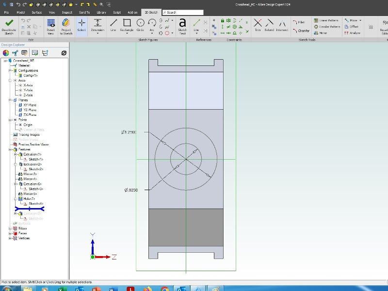
Sketch on the end face of the part for the piston rod boss. Only diameter dimensions are needed, both circles are constrained to be on the X-axis:
Extrude to length:
For each feature only one dimension is needed, which ripples through the part if changed. Careful placement of the original sketch avoids the need for many dimensions and construction lines.
Andrew
Edited By Andrew Johnston on 11/05/2022 21:04:46
11 May 2022 at 22:58 #597906Nigel Graham 2
Participant@nigelgraham2Interesting! What CAD "makes" are you using?
Those two exercises look as if in different ones.
Clearly you need know the difference between adding "metal" and cutting it away in those methods, and how to set the constraints – which are a new concept to me though I gather I might have been using them without knowing it, disguised by direct tool names.
12 May 2022 at 08:46 #597933David Jupp
Participant@davidjupp51506Nigel,
Andrew's example is in Alibre Design Expert (big brother to Atom3D), I don't recognise the software that Nicholas was using. In Alibre there are 'Boss' (add) and 'Cut' versions of all major tools, other systems I've looked at are similar in that respect.
Two points –
1. yes there are differences between systems, even those that work in a broadly similar way. Generally the concepts will apply across many systems, but points of detail may require slight adjustments to the methods. Tools may have different names too.
2. there are generally many different approaches that can be used to model any particular part. There is no 'right', 'wrong', or 'best' approach – though some might have pitfalls.
12 May 2022 at 22:01 #598018Nigel Graham 2
Participant@nigelgraham2Thankyou David.
Yes, I gained the impression of different approaches even with the same software!
And I do mean approaches by people who can use it properly, to advantage; not the sort of "work-arounds" I have used when unable to grasp the ways intended.
Alibre's "Boss" and "Cut" – probably akin to TurboCAD's "Boolean Add & Subtract" – the latter making a through-hole provided the sacrificial part to be subtracted does protrude from both surfaces.
'
Incidentally, and digressing somewhat, I think my previous, WIN-7 Pro, PC still holds a copy of a graphics programme called Pov-Ray. This is not a draughting package for engineers and architects, but for making lovely geometrical art-work! An expert at it and the maths might be able to create Fractal Dragons on it. My copy is an old edition and I don't know its up-to-date forms, but it works all by fairly simple command-lines holding the numerical distance, colour, etc. values. It reminded me of Hewlett-Packard's version of BASIC for users writing their own programmes to drive HP-made electronic test-equipment from (naturally) an HP computer, and process the readings. I don't know if the commands are a near-standard language like BASIC or C++, or Pov-Ray's own.
13 May 2022 at 07:22 #598067 JasonBModerator@jasonbPosted by Nigel Graham 2 on 12/05/2022 22:01:32:
Alibre's "Boss" and "Cut" – probably akin to TurboCAD's "Boolean Add & Subtract" – the latter making a through-hole provided the sacrificial part to be subtracted does protrude from both surfaces.
'
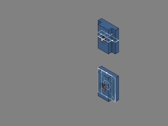
Not the same. They simply add the 3rd dimension to a 2D sketch for example the boss that the piston rod goes in was drawn as 2 concentric circles (2D) then extruded to then make the 3D boss with a hole in it. Had cut been chosen instead of extrude the ring would have been cut out of the part. This is the very basis of just about every 3D package, you need to grasp that before you can move forwards.
No sacrificial part is needed. The Boolean is generally used when you want to remove a complex shape from a part, have a look at this thread where it was used to remove the core from the pattern leaving what the finished casting will look like. Also used to remove the core from a solid block to produce the core box
Edited By JasonB on 13/05/2022 07:23:11
13 May 2022 at 09:44 #598085SillyOldDuffer
Moderator@sillyolddufferPosted by Nigel Graham 2 on 12/05/2022 22:01:32:
…
Alibre's "Boss" and "Cut" – probably akin to TurboCAD's "Boolean Add & Subtract" …
… my previous… PC still holds a copy of a graphics programme called Pov-Ray. This is not a draughting package for engineers and architects, but for making lovely geometrical art-work! …
My guess is Boss is what Freecad calls 'Pad' and SolidEdge calls Extrude, and Cut is Pocket. The commands work on sketches and faces.
Say you want a cube with a hole in it.
- By sketching: draw a square and extrude it to make a cube. Select a face, sketch a circle on it, and cut (aka pocket) the circle out of the cube – a negative extrude.
- By boolean: Create a cube by any means. Packages often have buttons for creating primitive shapes directly, but they can also be made by sketch/extrude. Drill a hole in it by creating a cylinder, moving it to where the hole needs to be, and subtracting ( aka 'cut', or 'difference' ) the cylinder from the cube.
Boolean methods are a bit of a booby trap in that they provide an obvious way of creating shapes, but it's not obvious that a model so constructed becomes ever more difficult to manage as it grows. I find it best to use booleans sparingly; good tool, but specialised. Jason's 'remove core from a pattern' example is a good one – most of his casting model is built from sketches, and then inverted with a boolean only at the end.
PovRay is a complicated beast, and also somewhat specialised! As Nigel says, arty folk use it, but so do engineers on occasion. PovRay is a 'render engine', a powerful graphics tool for making 3D models look good by providing massive control over colours, lighting effects, camera positions and much else. It's the software equivalent of fully equipped photographic studio.
As 3D-CAD is focussed on engineering needs, it takes a basic approach to the look of the finished models. If there's a need for better images, perhaps to sell the idea to investors, the model is processed with a render engine. These produce photo-realistic images, including things like creating a reflection of the model in the shiny surface of another model. Rendering is a complex subject in it's own right, and I wouldn't tackle learning it and 3D-CAD at the same time. My tiny brain would explode!
Dave
Edited By SillyOldDuffer on 13/05/2022 09:45:30
13 May 2022 at 23:09 #598200Nigel Graham 2
Participant@nigelgraham2Jason –
I see what you mean, but presumably you control the two extrusions so one creates a hole and not a solid core within the other. I have previously made hollow cylinders by extruding two concentric solids then subtracting the inner.
There is a trap here: if the "hole" is not slightly longer than the wall it might not appear; hidden by an extremely thin "skin". Easy enough to cure by extending the inner a little – except that in TC, sometimes the extension value moves it by that amount, instead. It may be linked to the way the object has been generated, I think, but I have never fathomed out what, or how to overcome that.
I followed that link but I'm afraid that though I am familiar with the concepts of cores and moulds, the sequence is of very advanced images created in a CAD package I don't know. Comments about "an hour or so" didn't exactly encourage me either. I'll leave CAD Racing to the experts!

Dave –
I'd not known PovRay has advanced that far!
TurboCAD has very powerful rendering functions for the advanced user, best left until one has reached that expertise.
However, at a basic level a simple tool-bar menu offers 4 or 5 instant-rendering options with a lighting default, from wire-frame to a somewhat heavy colouring-in. I used it for that cross-head.
Art the other end of the TC 3D and Rendering scale of user's skill and software woof, an English kitchen designer once displayed on the Users' Forum a beautiful, near-photographic image of a fully-fitted kitchen. He explained it as a sample of the fully-rendered TC drawings he creates to help negotiate the contract with his customers. It was a superb example of this use of CAD at a very high level; far superior to those property-speculators' scrappy "artist's impressions" of their intended architectural carbuncles.
He'd even depicted a bowl of glossy apples on the otherwise-empty work-top…. I didn't know work-tops can be empty!
14 May 2022 at 07:15 #598213 JasonBModerator@jasonbPosted by Nigel Graham 2 on 13/05/2022 23:09:00:
Jason –
I see what you mean, but presumably you control the two extrusions so one creates a hole and not a solid core within the other. I have previously made hollow cylinders by extruding two concentric solids then subtracting the inner.
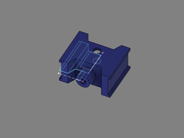
Alibre splits the Boss and Cut into two groups one that adds material, the other that removes it so you just select the one you want depending if you want the circle you have drawn to become a spigot or a hole. The yellow shows what each will do
Never had your "skin" issue as sketches are done on planes that have no thickness or onto a previously created surface.
14 May 2022 at 08:04 #598218David Jupp
Participant@davidjupp51506Nigel,
2 concentric circles in the same sketch, extruded (boss) in Alibre (and many other systems) will also give a hollow tube – it is the enclosed area in the sketch that defines the solid or hole that is being created.
Heavily nested sketches can give some interesting results!
14 May 2022 at 08:46 #598222Nealeb
Participant@nealebAs mentioned, if you set out to create a tube then extruding the space between two concentric circles is the way to go. But if you need to make a hole through an existing solid, then typically you can define its depth by specifying an exact depth (most useful if you want a blind hole), or link the depth to another point (e.g. the opposite face of the solid so that if you change the solid's thickness, the hole still goes exactly through it), or, depending on the CAD package, specify "through this part" or "through all parts". It's a matter of finding the right tools but there is the principle (sometimes overlooked in tutorial videos) that if you link ("use constraints"
 components then the model is usually more robust when changes are made than if, as here, you just make two dimensions equal.14 May 2022 at 09:26 #598226
Anonymous
Posted by David Jupp on 14/05/2022 08:04:07:…the enclosed area in the sketch that defines the solid or hole…
As per my example.
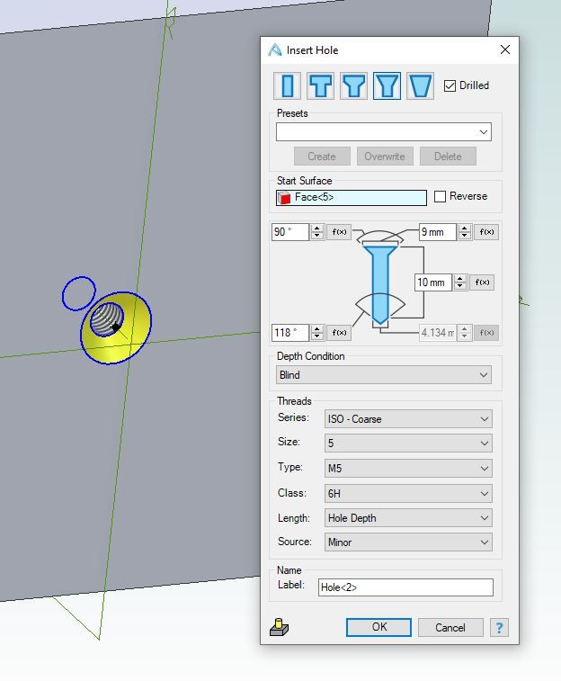
If a hollow tube, or shape, is inherently part of the design then I tend to implement it using sketches. But for smaller holes, especially if countersunk, counterbored, or threaded, I use the 'hole' function. The 'hole' function also allows one to take account of the drill point; useful when checking whether a blind hole will unintentionally break through or not.
Andrew
14 May 2022 at 10:28 #598231Nick Wheeler
Participant@nickwheelerAnother reason for creating holes using a function and not sketches is that you rarely want one. So patterning one feature, that created a custom countersunk, threaded hole with a drill point bottom is much easier than doing that when you've performed several operations to make it. And you can easily change the thread size on all of them when you discover that the original breaks out in an unexpected location.
Fusion doesn't differentiate between cut and additive extrudes until you've selected the profile. Then it makes an intelligent guess at what you want; one in a blank space is almost certainly going to be additive but could be a new body or component, so you have the option to select what you want. It won't allow you to choose cut if there's nothing to cut. One near or into another solid could be joined to it, cut into it, or not affect it at all. One inside an existing solid will be suggested as a cut, because that's most likely.
Extrudes can be a specific distance, or to an existing feature of some sort. Referencing relevant features(holes, centre lines, planes, axes, edges, faces etc) is best practice. You have the option to cut through all and if it's a through hole that's the one you want as it will update if you change any of the dimensions.
I can't imagine creating a simple cylinder just to subtract it from another another solid that was created from a sketch; adding a concentric circle to that sketch saves a lot of extra work, and is easier to understand when you look at your efforts six months later.
That leads me to another important point: name all this stuff. It's much easier to check 'main bearing extrude' than extrude22, or 'cambelt cover' than component37
14 May 2022 at 23:07 #598279Nigel Graham 2
Participant@nigelgraham2Sorry – I'm not quite clear what you mean.
Is this a function that generates countersunk or plain, threaded holes them? (Presumably you need enter the thread size and maximum depth.)
I am not sure why "rarely" wanted either. Machines are full of plain and threaded holes! In both TurboCAD and manual drawing I have never found it necessary to draw the thread, only to represent the hole as a circle or rectangle (an ellipse in an oblique, 3D view), depending on view type, annotated with its details.
The depth of a blind hole is important of course, but the diameter should be a function of the necessary strength – or perhaps of scale. So if it seems to me necessary to reduce it so the hole will not break through, I would want to know why. Have I over-estimated the bolt size for the part, for example, or left insufficient material by depth or breadth for the correct diameter?
'
I don't know Fusion, though I did briefly try it, so I can't follow exactly your comparison, but to me it looks no more or less work than the way I was using TurboCAD to draw the same thing. It does the same thing but in a slightly different way. There is though the crucial point about TC might or might not that differ from other CAD systems, that it has more than one internal method to generate a solid figure like a cylinder, and this gives the figures their own peculiar reactions to the various controls and commands.
'
I'll pass on Fusion muddling nouns and verbs, but I agree wholeheartedly with your point about naming part drawing should be natural to all filing-systems, be they electronic or paper. The modern computer allows long enough names for that. I recall one of the laboratory computers being so full of old and really, temporary, test-results no-one had really logged, that I called it "Garden Shed Computing".
Meaning the stereotypical shed: so full of old tins of dried-up paint, out-grown toys, corroded barbeques and such like there is barely room for a new garden spade. So buy a new, bigger shed….
You can work only to Part Numbers, perhaps with vague generic titles like "Bearing" or "Cover"; and this is typical industrially, not least for confidentiality when sub-contracting component manufacture. However it does need quite a lot of self-discipline to maintain such a system for oneself in a hobby, because it needs you also to compile and maintain a coherent index (on the PC or in a note-book).
I used somewhat similar to help in preparing one project: a spreadsheet version of the parts-list on the drawings, extended to group the materials, fastenings and similar machining operations. E.g. find the material for all the parts turned from one-inch diameter steel, and concentrate on just the turning of all those parts. Leave any second-operations until the turning is complete; and group those with related second operations on parts turned from other diameters. (Why set up a rotary table or angle-vice, say, twice?)
Now that is a planning not design approach, so the medium used for the drawings does not matter (in that case, it the old Blackgates-published prints for a Stent T&C grinder). However, I gather some CAD systems have some form of planning functions, although I do not know them.
15 May 2022 at 07:10 #598284 JasonBModerator@jasonb
Alibre has a "hole" function that is ideal for drilled, tapped, CSk, etc holes or a combination of those. It has simply clicked options so if your hole is drilled then it will show it with a conical end, if CSK it will show that, if tapped then it can represent the thread on the 3D model and will also size the hole and CSK to suit say an M5 CSK socket screw, you just click one of the many threads listed.
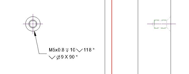
When it comes to producing a 2D drawing from that 3D model the Alibre will correctly show the thread as two lines, the CSK and the drilled end and add the annotation.
Had the hole been done as a simple circlular sketch that was then cut it would have needed a second operation to chamfer the edge to produce a CSK. It would have had a flat bottom which if the drawings are going to be used by others will make them think a flat bottomed hole is needed. It won't show the thread correctly on the drawing and there will be no not to say how deep or what thread it is unless added manually and hope you remember the size from the design stage,
15 May 2022 at 08:44 #598288Nigel Graham 2
Participant@nigelgraham2Jason –
Thank you for explaining how Alibre works with extrusions and threads.
I think the surface skin effect I've encountered in TurboCAD could be a rounding error, perhaps related to the numerical limits I've set. Although this controls what is displayed in the dimensions, I don't know if it also affects the accuracy of the drawing. I would not expect it to though, otherwise polylines and snaps would keep failing, and they don't, but it is an odd effect that was frustrating until I twigged (or someone on the Users' Forum told me) what I had to do.
.I like the way it prints the thread details for you, but I am afraid I am not clear what it means. I don't know if there is a trade convention by which the 10mm shown is always either depth of full thread or to the tip of the cone – whichever it is. The hidden detail lines show the thread meets the start of the cone, but is it literally to be that? A conventional symbol might meet some official standard, but of no use if it is likely to be ambiguous.
I've not regarded showing the drill-point portion as so important, preferring instead simply total depth and thread depth. Even so I would add it, symbolically not accurately, where needed.
My design stage is usually the stage at which I am also drawing the thing, or have earlier drawings showing what's needed, so "having to remember" is not an obstacle. Indeed, some of my drawings are of things already made from a rough pencil sketch at best, and to help me work out how make the next bits fit them.
(At work, a colleague once showed me a drawing that demanded something like an M3 thread full-depth without breaking through… the material thickness was all of 4mm!
It is all too easy for details to be made by draughtspeople who know how to draw to the last BS / ISO full-stop in pictorial standards, to pass "Design Reviews" of those not of part function; but who have had little or no real experience of making anything. I have seen this even before CAD became nearly universal!).
When actually drilling a hole to maximum depth I do of course set it from the point contacting the metal.
-
AuthorPosts
- Please log in to reply to this topic. Registering is free and easy using the links on the menu at the top of this page.
Latest Replies
Home › Forums › CAD – Technical drawing & design › Topics
-
- Topic
- Voices
- Posts
- Last Post
-
-
Building Bernard Tekippe’s Precision Regulator
1
2
3
Started by:
Chris Raynerd 2 in: Clocks and Scientific Instruments
- 11
- 51
-
27 April 2025 at 19:22
 Michael Gilligan
-
Bending EN24t
Started by:
vintagengineer in: Workshop Techniques
- 8
- 15
-
27 April 2025 at 19:07
SillyOldDuffer
-
Stuart Twin Victoria (Princess Royal) Mill Engine
1
2
…
49
50
Started by:
Dr_GMJN in: Work In Progress and completed items
- 32
- 1,234
-
27 April 2025 at 18:01
Dr_GMJN
-
mt4.5
Started by:
Matt Smith in: General Questions
- 3
- 3
-
27 April 2025 at 15:43
DC31k
-
Small horizontal mill – capabilities?
Started by:
ell81 in: Beginners questions
- 14
- 16
-
27 April 2025 at 15:25
 Bazyle
-
Anyone know about wells and Victorian plumbing?
Started by:
Ian Parkin in: The Tea Room
- 11
- 16
-
27 April 2025 at 15:04
old fool
-
French Curves
Started by:
 Michael Gilligan
in: CAD – Technical drawing & design
- 2
- 2
-
27 April 2025 at 13:02
 JasonB
-
Some help with a Cowells speed controller needed.
Started by:
Hollowpoint in: Electronics in the Workshop
- 3
- 5
-
27 April 2025 at 13:00
Hollowpoint
-
Change Wheels
Started by:
Julian Goodyear in: Workshop Tools and Tooling
- 10
- 24
-
27 April 2025 at 12:22
halfnut
-
Amazing Fellow and his musical machines..
Started by:
Joseph Noci 1 in: The Tea Room
- 1
- 1
-
27 April 2025 at 12:02
Joseph Noci 1
-
Scam email
Started by:
Ian McVickers in: General Questions
- 10
- 10
-
27 April 2025 at 09:28
 Dell
Dell
-
Power hacksaw – powerful banging when running
Started by:
ell81 in: Beginners questions
- 8
- 11
-
27 April 2025 at 08:21
John Haine
-
Emco FB2 and Maximat Mill?
Started by:
beeza650 in: Beginners questions
- 3
- 3
-
27 April 2025 at 07:29
Diogenes
-
How To Make A Pressure Gauge Syphon?
Started by:
 MEinThailand
in: CAD – Technical drawing & design
- 4
- 7
-
27 April 2025 at 07:10
 JasonB
-
Drummond round bed
Started by:
old mart in: Manual machine tools
- 3
- 4
-
27 April 2025 at 07:10
 David George 1
-
Dodgy car parts a new low
Started by:
jon hill 3 in: The Tea Room
- 11
- 13
-
26 April 2025 at 22:57
 Robert Atkinson 2
-
Metric Thread Cutting Without Conversion Wheel
Started by:
Nigel Graham 2 in: Hints And Tips for model engineers
- 7
- 10
-
26 April 2025 at 21:04
Nigel Graham 2
-
minimag set up
Started by:
Dalboy in: General Questions
- 3
- 3
-
26 April 2025 at 20:58
old mart
-
My week this week! My workshop videos
1
2
…
11
12
Started by:
Phil Whitley in: The Tea Room
- 14
- 289
-
26 April 2025 at 20:33
Phil Whitley
-
Mechanical lubricator
Started by:
 Garry Coles
in: General Questions
- 4
- 6
-
26 April 2025 at 19:53
Speedy Builder5
-
Lady Stephanie
Started by:
 Steve Huckins
in: General Questions
- 6
- 15
-
26 April 2025 at 19:00
duncan webster 1
-
All things Beaver Mill
1
2
…
7
8
Started by:
Robert James 3 in: Manual machine tools
- 39
- 197
-
26 April 2025 at 18:46
Mark Guy
-
Myford Super 7 restoration problem.
Started by:
 Bootlegger Blacky
in: Manual machine tools
- 4
- 6
-
26 April 2025 at 16:07
 Bootlegger Blacky
-
Tensile Strength Machineability
1
2
Started by:
kevian64 in: Beginners questions
- 12
- 28
-
26 April 2025 at 15:39
 JasonB
-
leftover gear oil uses?
Started by:
jon hill 3 in: Beginners questions
- 5
- 6
-
26 April 2025 at 12:53
halfnut
-
Building Bernard Tekippe’s Precision Regulator
1
2
3
-
Latest Issue
Newsletter Sign-up
Latest Replies
- Building Bernard Tekippe’s Precision Regulator
- Bending EN24t
- Stuart Twin Victoria (Princess Royal) Mill Engine
- mt4.5
- Small horizontal mill – capabilities?
- Anyone know about wells and Victorian plumbing?
- French Curves
- Some help with a Cowells speed controller needed.
- Change Wheels
- Amazing Fellow and his musical machines..






 components then the model is usually more robust when changes are made than if, as here, you just make two dimensions equal.