New To CAD? No, but….
New To CAD? No, but….
Home › Forums › CAD – Technical drawing & design › New To CAD? No, but….
- This topic has 156 replies, 25 voices, and was last updated 28 May 2022 at 13:09 by
blowlamp.
-
AuthorPosts
-
10 May 2022 at 09:02 #597685
lee webster
Participant@leewebster72680You could be right about TC. There are probably many who sing its praises. I am not one of them!
Out of all the "free" CAD programmes I would recommend Solid Edge to a begginer closely followed by Designspark Mechanical, then FreeCAD. Fusion 360 has too many drawbacks to make it worthwhile, and it might get worse. Are there any other free CAD packages?
10 May 2022 at 09:24 #597691Hopper
Participant@hopperWhat's the best freeware to draw 2D images, suitable for doing dimensioned drawings to go with MEW magazine articles?
I've no interest in graduating to 3D in the future etc. Moving off the back of a fag packet is a major step for me.
Edited By Hopper on 10/05/2022 09:25:23
10 May 2022 at 10:40 #597698blowlamp
Participant@blowlampIt's plainly obvious that the reason for your difficulties is because TurboCAD is too difficult for you to learn. You are not getting help from other TurboCAD uses because there don't seem to be any here.
I tried TurboCAD quite some while ago and like you, found it heavy going, so I moved on. I've tried Fusion 360 as well as Solid Edge, but despite their greater capabilities in some respects I find them quite regimented in their model creation and find MoI more to my liking and for what I use it for, it is very 'fluid' in use.
You do seem to be stuck in the idea that because others can successfully use TurboCAD, then it must be a failing on your part, because you can't, but like all tools, software is there to enable to get the job done.
If a tool is blunt or broken then it should be sharpened or replaced and if a tool is poorly designed it should be exchanged for something better.
I think you are flogging a dead horse with TurboCAD and what you need to do is find some software you can work with.
Martin.
10 May 2022 at 10:50 #597699Nick Wheeler
Participant@nickwheelerTime for some construction lines.
Draw one horizontally near the origin, so that you can see it move when you constrain it to the origin. Doing this means you know that the line is where you wanted it, not just looking like it.
Create the first circle on the origin, and the second one on the line. That enables you to add easy(and easily editable) dimensions. Do the same for one of each of the cover holes, so you can use a radial pattern once they're actual threaded holes in the solid.
Draw the outside profile of the part, dimensioning it from the origin, construction line and centre holes as necessary. DON'T use coordinates for this, for a couple of reasons: it's lots of extra work which the computer can do better, but mostly because it's what is causing your model to break when you try and alter it later. If the thing is symmetrical, you only need to draw half and mirror the other which saves time, effort and potential screwups. This is basic 2D draughting, so is well within your previous experience.
Extrude it, so you now have the solid you actually want. Work on that, creating extra planes and 2D drawings for the required features. And it should only be moved, placed, aligned or joined using the program's tools NOT moves. Because as you've found, moves are another excellent way of breaking the model in all sorts of random ways.
TurboCad is horrible to use, but all of the above applies to any of the programs.
10 May 2022 at 11:01 #597700SillyOldDuffer
Moderator@sillyolddufferPosted by Hopper on 10/05/2022 09:24:29:What's the best freeware to draw 2D images, suitable for doing dimensioned drawings to go with MEW magazine articles?
I've no interest in graduating to 3D in the future etc. Moving off the back of a fag packet is a major step for me.
Edited By Hopper on 10/05/2022 09:25:23
I recommend QCAD. The free Community Edition is more than good enough for most 2D purposes, though I coughed up for the Pro version which adds various 'go faster' options such as a tool that removes line segments with one click, an operation taking 3 or 4 in Community Edition. Runs on Windows, Apple and Linux : the licence covers all of them, and multiple installations, and it's not time limited. Downloaded from here. Note the download is a 15 day trial of the Pro version, which is converted to Community by disabling the Pro features: it's the same download.
Alternatively, LibreCAD is a fork of the QCAD community edition: a little flaky when it first came out years ago, but believed OK now: I haven't used it in anger, or looked for differences.
Dave
10 May 2022 at 11:03 #597701Ex contributor
Participant@mgnbukWhat's the best freeware to draw 2D images, suitable for doing dimensioned drawings to go with MEW magazine articles?
With the demise of free-to-use Draftsight I moved to NanoCad, after trying QCad & a QCad derivative
whose name escapes me at the momentLibreCad (thanks Dave ! ). NanoCad appeared to handle my legacy Draftsight drawings better than QCad & I could configure the interface almost identically to my Draftsight arrangement (which I configured almost identically to AutoCad LT), so there was little new learning required on my part. Where there are differences, the Help files have been adequate. The only feature I miss is NanoCad is incapable of drawing a line tangential to 2 circles.NanoCad is a Russian product, though, which – given the current situation – may be a choice you don't wish to make.
Nigel B.
Edited By mgnbuk on 10/05/2022 11:05:06
10 May 2022 at 11:25 #597703Hopper
Participant@hopperThanks SOD and MGN. I shall go and have a play with them.
10 May 2022 at 14:20 #597712Nigel Graham 2
Participant@nigelgraham2I have just experimented with TC – SE file compatibility.
There is only one compatible of the many file-types both offer, and that is .DWG
.I opened and saved a copy as name.dwg, one of my few successful 3D name.tcw drawings – actually a slid-apart, sectioned cross-head. Then I opened that in SolidEdge. I realised it might lose details such as colour and opacity in translation. (The rendered original is in two colours.)
Though originally in 3D, only the 2D plan opened in SE. All the other views showed only a flat plane-line.
So not a good start!
Jason –
I am not "reluctant" to find tutorial material, but most of it is videos that I don't find helpful. TurboCAD came with a CD of pdf documents I can follow at my own pace.
I have two general CAD primers, but obviously these cannot describe specific makes of CAD.
CAD For Model Engineers, by DAG Brown, looks very dated by its cover photo (remember beige desktops?) and uses only 2D drawing, but does cover the basics.
The other is Neill Hughes' CAD For The Workshop – oddly using American spelling for the metre despite British author and publisher – very much up-to-date, covering both 2D and 3D to some depth. Hughes also lists the main makers of these programmes, with brief comments on them. He mentions SolidEdge but I think writing when that was still very much an industry-only system.
The problem really is not knowing what a Layer or an Extrusion is, but how to use them in the particular system you buy. They all do the same thing – geometrical plotting – but differ considerably in style and difficulty.
I copied TurboCAD's on-line 'Help' document's Contents page, and edited it by MS 'Word' and 'Excel' into a printed, proper alphabetical index written in MoD-style noun, adjective. adjective format. This greatly facilitates searching an otherwise frankly shambolic 800+ pages of the sometimes-helpful. I must admit I was very surprised I could do that with a pdf file.
Having up-rated my TC to TurboCAD 2021, I will need repeat the exercise – if it's still possible – but the document is even longer!
I have searched for other printed CAD reference-books, but found none. A dealer in second-hand technical books told me he refuses to take any IT material because it goes out of date too rapidly.
'
Martin –
I think so too! I know others who have tried TurboCAD but failed completely, making far less progress than me.
I installed Solid Edge (CE) largely after reading discussions here about it; but was deterred by the publishers' own web-site, and by it being no more intuitive than TurboCAD – less so if anything. It seemed to expect background knowledge of similar CAD systems – "synchronous" drawings? – then after a brief taste of it, leave you to it.
I would be starting from scratch. As if getting stuck machining the cylinders for my half-built engine, so starting the entire project all over again to a different design.
Also, there is the file-transference problem I described above. It would give me two incompatible CAD systems and drawing sets – and brain-fade!
.
Nicholas –
I had drawn the cylinder covers in 2D, but copied them to a new 3D drawing.
I forget if I plotted the bolt-holes by Radial Copy or construction – the latter I think, snapping copied circles to intersections; a less efficient way but same result.
I don't dimension anything by co-ordinates, but sometimes use them for working out locations. Normally I work from the (x, y) or (x, y, z) origin but place items relatively to each other by their distances, not co-ordinates.
This system also works in 3D. E.g. to put a cube on the face of another, I assemble them corner-to-corner then translate the donated one by the right distances. This is not possible if the second part is perhaps a cylinder, with no definite edge-point. Then I need to calcuIate its location because I can't grasp the proper method.
The proper TC term for translating or rotating an object is not "Move" but "Delta" or "Rot [ation]" $ n" where $ is the axis-parallel and n your typed-in value, a system with 10 possible entries in 2D, 15 in 3D; so great flexibility very easily. If I use it wrongly or needlessly is hardly TurboCAD's fault!
And two boxes called Delta D and Delta A, without axes. Not noticed those before – I don't know their purpose.
.
The one advantage I would have of moving to Solid Edge is the greater availability of help, here and in my club; but whether it is any easier to use than TurboCAD is another matter.
10 May 2022 at 14:23 #597713SillyOldDuffer
Moderator@sillyolddufferAnother reason maybe why Nigel is having so much trouble: trying to run a marathon before learning to walk!
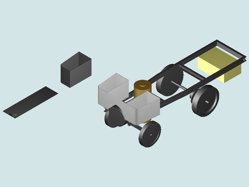
Nigel's wagon is a hard target for a beginner.

The wagon isn't a simple part – it's an Assembly of Parts. Not good to plunge into Assembly until reasonably up to speed creating single parts.
The wheels, axles, boiler cylinder and boxy shapes on Nigel's wagon are all Ordinary-Level objects, a good place for beginners to start.
The swept U-beam and tanks are Advanced-Level objects, not normally attempted until the basic concepts are being comfortably applied by the learner.
Assemblies introduce another level of complexity: relationships between parts: fixed, sliding, rotating, cams etc. Not a good idea to start a Black-Belt fight with an Assembly before getting a Yellow-Belt in Part building!
I'm unwilling to slag off TurboCAD or any other software without having road tested it. However, watching a couple of tutorials revealed a product with many similarities and differences to it's competitors. A few things jumped out:
- The difference between 2D and 3D operation is blurred: other software I've used clearly separates the two. I suspect the blur is due to TC's heritage, and although liable to confuse a beginner, could be useful to an expert. It would allow sketches intended to make 3D objects to be drawn with a full-throttle 2D editor, which is good provided the operator understands the limitations. I fear the feature makes it easy to draw things that look OK but can't convert to 3D. (Like Pat's lines not connecting.)
- Looks like TC displays new solids as line drawings by default. Other software makes it more obvious a new item is a solid rather than a drawing, by filling it in. (Line drawing available, but not normally used.) Again, this might be a heritage thing – older computers didn't have the grunt needed to render 3D graphics at high speed. I found it slightly confusing – is the thing on screen 2D or 3D?
- In 3D, TC allows all sorts of stuff to be done in parallel. Dimensions, colours, materials, can all be changed in the 'sketch', and several objects can created at the same time. Other software encourages one-part one sketch. My feeling is this approach improves expert productivity at the cost of confusing beginners with a million choices!
- TC seems to mixes expert and normal choices together. For example, 'Simple Extrude', can generate a solid or a surface. This is good for experts, but the beginner will almost certainly not want a surface, and if he chooses it, there will be trouble later! Likewise, the difference between a line and a polyline.
I liked what TC does, but my feeling is it would be harder to learn than the others, and they're not easy either!
On the easy to learn front, I've not had time to look at MOI yet – Blowlamp makes it look good though! Quick research suggests MoI isn't parametric like the others, which might make it more arty than engineering, but that may not matter. Dunno.
Too much to do, so little time…
Dave
Edited By SillyOldDuffer on 10/05/2022 14:24:17
10 May 2022 at 15:45 #597727GordonH
Participant@gordonhPosted by Nigel Graham 2 on 10/05/2022 14:20:14:I have just experimented with TC – SE file compatibility.
There is only one compatible of the many file-types both offer, and that is .DWG
………
Though originally in 3D, only the 2D plan opened in SE. All the other views showed only a flat plane-line.
Nigel,
SE will treat a DWG file as 2 diemnsional. You need to Export the model from TC. The one time I needed to export from Fusion, for opening in SE , I was asked to supply an IGES file, SE lists various file types including asm assembly documents, IGES and STEP. Hopefully, your updated TC will be able to export a suitable file type.
Gordon
10 May 2022 at 15:54 #597728lee webster
Participant@leewebster72680Nigel, One thing that seems to have not been mentioned is that 3D design can be fun! I often design parts without having any use for them, especially flywheels with spokes. Ooo, I do love a spoked flywheel. I have even designed said flywheel, 3D printed it ( in two halves with location points so it goes back together again) and then cast it in aluminium. I didn't need the cast flywheels, so I cut them up to use on another project.
10 May 2022 at 18:43 #597735Nigel Graham 2
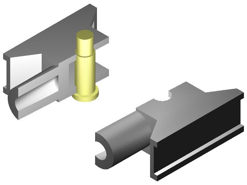
Participant@nigelgraham2This is the TurboCAD drawing I was experimenting with trying to copy it to SolidEdge, as a jpg copy. #
I cut with the "Slice" tool – I think it's called.
The pin is yellow simply for contrast, not to indicate being of brass! It's actually one of my steam-wagon engine's crossheads, made from a raw casting pair I bought from the waifs-&-strays tray on M.J. Engineering's stand at a show. Of cast-iron, they were probably for a 7-1/4" g. locomotive originally, and a bit over-large for my engine, but since the engine is fully-enclosed I won't tell anyone if you don't!
One modification I have made, not on the drawing, is to drill a sloping oil-hole down each of the ramps flanking the piston-rod spigot, and cutting into the edge of the guide-bar channel, to scrape oil from the bar and feed it to the pin. (The engine is vertical.)
The drawn body is an extrusion, vertically in this view, with the channels and cavities made by subtracting appropriately-shaped blocks infiltrated into the main extrusion.
ordon –
I can't find any "Export" command anywhere; not in TC, not in File Explorer.
Lee –
I was rather hoping it would be "fun", or certainly rewarding, too!
A lot of my exercises to try specific tools are not of anything special at all, just simple geometrical shaped to work out how to use some command or other.
Seems a shame to have made those flywheels then broken them up. Use them as hand-wheels perhaps?
Dave –
I realised trying to draw the wagon in more than an sort of "artist's impression" would be too difficult for me, though perfectly possible for an expert user. Really, it was exercise to see how far I could take it.
TurboCAD does not use the "sketch" term and concept. Instead it allows creating 3D images from a mixture of library solid images and generating from plane figures. So I suppose it is like other CAD systems in that regard, but perhaps less streamlined.
The lines problem Pat describes applies in 2D as well as 3D. One of my first stumbling-blocks was in trying to represent a cross-section by the conventional hatching. It needs the shape to be a closed polyline to work; but as Pat describes this problem is often easily cured by trimming extended lines.
TurboCAD's 2D/3D blur may lie behind what is known to trap many beginners. It is very easy to switch between the two modes in mid-drawing, deliberately but wrongly, or accidentally by mis-selecting the command symbol. Unfortunately this can create havoc!
10 May 2022 at 18:49 #597737 JasonBModerator@jasonb
A .jpg is no good as that is a photo file.
Use .step, stl or igs
If you click "file" top left and then "save as" you get a drop down of about 20 file types, use one of the above to open in SE
Edited By JasonB on 10/05/2022 18:55:41
10 May 2022 at 19:10 #597741Nealeb
Participant@nealebI noted the comment a few posts ago about how careful you need to be to make sure that a sketch encloses an area for extrusion to a 3D body with no gaps, and suggesting over-length lines which are trimmed back. I would suggest that this indicates someone coming from a non-3D background and who is not yet up to speed with using the 3D tools. In particular, using constraints to control things like lines meeting at a point and using dimensions to control line length rather than drawing correct length lines.
I have done some tutoring for local club members amongst others and one thing that quickly became clear is that it is probably more difficult to transition from years of 2D engineering drawing experience to 3D CAD than it is from a position of ignorance! For example (from among many) on a drawing board, a line is a line and while it might be possible to lengthen it, position and angle are fixed. On a screen, a line can have length, position and angle changed as you wish. It changes the way you approach things. I often create an object – line, circle, rectangle – of roughly the right size and in roughly the right position, but deliberately not exact. I then apply constraints and specific dimensions as required to tweak it into the right place/size. It's a mindset thing, and it's the thing that is often missing from Internet video tutorials. A quick whizz with the mouse and a "that was easy" doesn't always explain the underlying principles!
Edited By Nealeb on 10/05/2022 19:11:23
Edited By Nealeb on 10/05/2022 19:12:29
10 May 2022 at 20:27 #597752SillyOldDuffer
Moderator@sillyolddufferPosted by Nigel Graham 2 on 10/05/2022 18:43:23:
…
I can't find any "Export" command anywhere; not in TC, not in File Explorer.
,,,
May be hidden in plain sight. Try 'Save As'. It might allow a choice of different file types, providing export by a different name.
Dave
10 May 2022 at 20:44 #597753blowlamp
Participant@blowlampUsing simple tools like Offset and Boolean Intersection I made a Crosshead model.
MoI isn't a Parametric modeller but it's still quite nifty.
Video here, including a very basic mistake.

Martin.
10 May 2022 at 22:12 #597760Nigel Graham 2
Participant@nigelgraham2Jason, Dave –
Cor! It works!
Thankyou. I know a jpg file is a photo. I made that version simply to show here.
The types you list are new to me. I've just opened TurboCAD and SE, found TC includes STL files, and tried it, using the Desktop as a convenient carrier. Though the route to doing so is not immediately obvious, I found how to open the file in SE, and save it under a modified name in what I take is SE's default type (name.asm).
All I need do now is find how to make SE work…..
One thing SE revealed is that the spigot for the piston-rod is not quite on the cross-head's axis. This is not apparent on TC's images, but it shows in SE's rendering. I hope my machining of the two real cross-heads was a bit more precise – well, nowt a bit of shim under the guide-bars won't sort out.!
Nealeb –
I know the trap you mean although not the word "constraint". TC has them, as the word appears in the "Help" index I made, but I don't use them at my level. I use its other ways to avoid the problem of lines not meeting, including snaps and "primitives". If I need draw a rectangle or other polygon I use the rectangle or polygon tool.
I may have a rather ironical advantage over your students in having never been a professional draughtsman, so although used to orthographic drawings their methods are not ingrained.
As I do not know what "Constraints" are, I have just opened TurboCAD to gain some idea from its on-line 'Help' errr, manual. The Contents said page 863, of well over 2000. So I selected Page 863 and the word does not appear on any page anywhere near it.
The book's page number is not necessarily the pdf display number. If so, any given entry could be anywhere in that mass of very scrappy information.
Also of course, the Help manual does not tell you what the terms mean, only how to control them in TurboCAD – and whether they are available in the edition you have.
That point would apply to learning any make of CAD. You need understand the concepts and terms before you can learn how to choose them appropriately and use them correctly, in the particular software you have. That background information is not at all easy to find.
10 May 2022 at 22:22 #597761 Michael GilliganParticipant@michaelgilligan61133
Nigel,
I am following this discussion with interest, as I have some empathy.
Allow me please to offer this: **LINK**
https://www.turbocad.com/content/parametric-constraints
MichaelG.
10 May 2022 at 22:24 #597762Nealeb
Participant@nealebI was also a TurboCAD user and went through a number of updates of the product. I spent quite a lot of time trying to get the 3D bit to work, carefully followed the manual to try to learn it, and eventually gave up as too difficult! I then moved to OnShape, then Fusion 360, then Solid Edge. I still use both the latter two although I have given up OnShape.
Briefly, constraints are a bit like snaps, except that because you can generally move things around and redimension them in a 3D CAD package, they are more than just a snap as they define a permanent relationship between two objects. For example, if you constrain the centre of a hole be on the midline of a component, it will stay on the midline even if you change the size of the object. It's a very powerful technique, to the extent that the mantra "don't dimension if you can use a constraint instead" is generally valid. Failure to use constraints properly is where a lot of models fall apart when you try to modify them later.
I see from MichaelG's post (arrived as I was typing this) that TurboCAD is now using the same core engine as Solid Edge and other products, so perhaps they are actually moving away from a 2D drafting package to a 3D modeling package.
But we all bring different baggage to the table and the fact that I'm more a software than mechanical engineer is probably a useful attribute!
Edited By Nealeb on 10/05/2022 22:26:27
11 May 2022 at 02:03 #597775 PatJParticipant@patj87806
I created 2D drawings daily for 18 years before I decided to try and learn 3D modeling.
I think "3D modeling" is a more accurate term, in lieu of "3D drafting" or similar terms.
You are no longer drafting per se, but rather created these solid models.
I have to agree that a long-term knowledge of 2D CAD is a detriment to learning 3D modeling; it was for me at least.
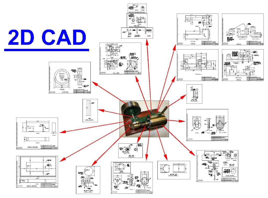
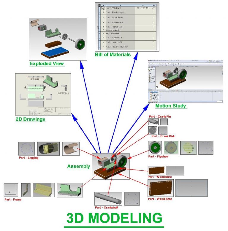
I had to create the graphical maps of information flow, which I posted in my other post, to clarify the differences in information flow in 2D CAD and 3D modeling (I will copy them below).
In 2D CAD, you created drawings that are isolated views.
In 3D modeling, you create individual models, and everything else emenates from those models, such as assemblies, 2D drawings, bill of material, motion studies, exploded views, etc.
I understand computer programming, and so I was simultaneously trying to figure out what the 3D program was doing from a computer program standpoint, and what equations it was using.
I found a good Solidworks tutorial book, but as mentioned by others, a tutorial video or book can be of limited usefulness when beginning to learn 3D.
The book I had stepped you through one feature at a time, and many of the features where ones that I would never use. The examples tended to be simplistic, and they did not address my specific need, which was how to model antique steam engines.
There was no guidance about how to combine the most useful and effective features together in order to efficiently make a 3D model.
When drawing in 2D, either on paper or on the computer screen, you basically lower the pencil, drag the pencil to create a line, and then raise the pencil. The end result is a 2D drawing.
My greatest difficulty is obtaining a broad overview of exactly what the 3D program was doing, and more importantly, understanding what it was that I was trying to make the program do, so that untimately I could produce a 2D drawing.
Understanding of the 3D modeling process gradually crystalized in my head over about a 1 year period, and once I understood the fundamentals of how a 3D program operates, and the various features they offer, then I could begin to figure out how to start creating steam engine models.
My first 3D models were absolute junk, but with each model there was experience gained, and I would learn a few more tricks and features.
It took me a solid year to learn 3D modeling as it applied to steam engines.
The green twin oscillator engine that I made originally started as a test to see if I really knew how to use 3D modeling. Much to my surprise, I was able to finally make quality 3D models for the green twin, and assemble them into an engine that would function virtually.
It was at that point that I said "I finally get it".
Not that I will every know every aspect of 3D modeling, but I can hold my own.
It was a triumphant point to reach, because my frustration level with trying to learn 3D was off the charts.
One tends to think that if you have mastered a 2D CAD program and used it for 18 years on a daily basis, then learning 3D modleing should be a shoe-in. Not so !!!
I basically had too much money invested in a 3D program to let it go to waste.
It was a matter of learning Solidworks, or die trying.
Edited By PatJ on 11/05/2022 02:13:31
11 May 2022 at 02:20 #597776 PatJParticipant@patj87806
3D modeling is parametric-style design.
I recall asking the question "What the heck is parametric design?".
The beauty of parametric design is that a change to any 3D model automatically propogates to its related drawing(s), and thus every view (such as left, right, top, bottom, side, and isometric) in a 2D drawing automatically changes when the associated model changes in dimension.
The power of this one feature cannot be overstated.
It would be the equivalent of changing a front view in 2D CAD, and having the right, top, side, bottom, and isometric views automatically change in a corresponding fashion.
The individual 3D models that you create are the "base" of the design.
Changes to any model not only automatically reflect in the 2D drawings, but also reflect in related assemblies, bill of material, motion study, expoloded view, etc.
Parametric means that everything is linked together in a web of interrelationships.
.
Edited By PatJ on 11/05/2022 02:23:49
11 May 2022 at 02:26 #597777 PatJParticipant@patj87806
I have written my own tutorials with the intent to help others perhaps avoid some of the grief I experienced when learning 3D modeling.
Writing your own tutorial also forces you to reach a deep understanding of what a 3D program is doing.
If you can put it into words, you are generally forced to much better understand it yourself.
.
11 May 2022 at 02:31 #597778 PatJParticipant@patj87806
A word about constraints………
I initially paid close attention to constraints, and tried to use them.
Untimately I found constraints to be very counterproductive to what I was trying to do (create 3D models for steam engines).
Constraints too often caused unintended changes in the model.
These days, I avoid constraints, and avoid them like the plague.
Without constraints, I can make changes to the model and sketches, and avoid the dreaded "3D model implosion".
I know some will howl with derision at someone not using constraints, but it is what it is, I don't use them, and I find them counterproductive.
.
Edited By PatJ on 11/05/2022 02:31:47
11 May 2022 at 02:34 #597779 PatJParticipant@patj87806
My first questions with 3D modeling were very fundamental and basic:
1. How do I make a 3D model?
2. How do I create a 2D drawing from that 3D model?
It took me a while just to figure this out.
.
11 May 2022 at 02:54 #597781 PatJParticipant@patj87806
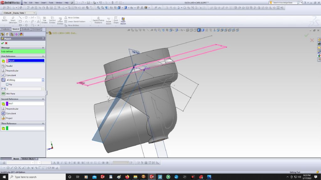
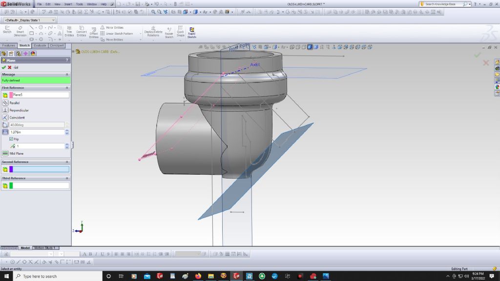
One of the last puzzles that I figured out with 3D modeling was how to insert planes, and manipulate those planes.
Without mastering the insertion and manipulation of new planes, you will not be doing any sort of complex 3D modeling.
Again, the tutorials showed how to insert planes, but did not really explain when/where/why I should do this, or how to do this to the best advantage.
When a model is first started (in Solidworks anyway), three planes are visible (if you have plane-visibility toggeled on), which are the front, top, and right side planes.
Any of these planes can be copied and offset out some distance from its original location.
I always start my 3D model centered on the origin of the front, top and side planes.
A new plane can also be rotated, and it took me a while to master this trick.
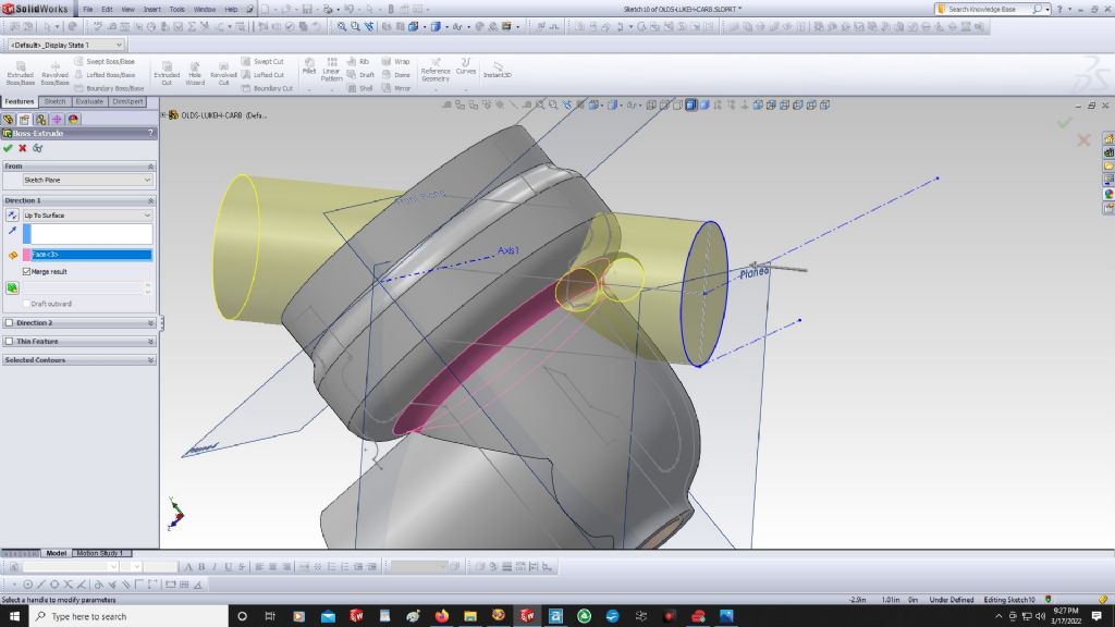
You can create a sketch on an offset plane, and then extrude back to the rest of the model.
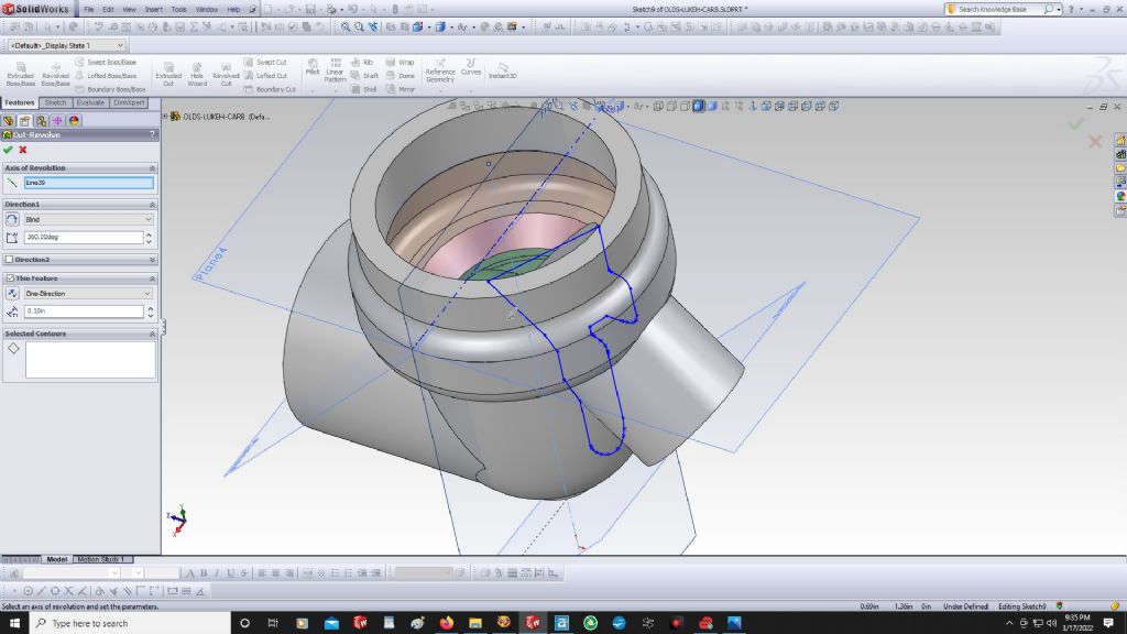
An example of using an offset plane is the creation of the fuel inlet on a Lunkenheimer carburetor body, as shown below.
I had to sweep the interior cut again after I added the boss, so perhaps there is a better way to do it, but you get the idea about planes.
.
Edited By PatJ on 11/05/2022 02:55:43
-
AuthorPosts
- Please log in to reply to this topic. Registering is free and easy using the links on the menu at the top of this page.
Latest Replies
Home › Forums › CAD – Technical drawing & design › Topics
-
- Topic
- Voices
- Posts
- Last Post
-
-
Myford S7 Taistock Adjustment
Started by:
 Harry Wilkes
in: General Questions
- 8
- 10
-
5 April 2025 at 01:19
 Steviegtr
-
How to wire up 3 phase motor and 3 phase converter?
Started by:
ell81 in: Beginners questions
- 7
- 8
-
4 April 2025 at 23:34
Emgee
-
Problem getting the right parameters on a VFD
Started by:
Robert Graham in: Electronics in the Workshop
- 1
- 1
-
4 April 2025 at 22:06
Robert Graham
-
What Did You Do Today 2025
1
2
3
4
Started by:
 JasonB
in: The Tea Room
- 23
- 78
-
4 April 2025 at 20:57
Nigel Graham 2
-
Powered hacksaw – blade lift for the return stroke
Started by:
 Sonic Escape
in: General Questions
- 8
- 17
-
4 April 2025 at 20:00
 Nicholas Farr
-
Damp proofing concrete floors
Started by:
Duff Machinist in: General Questions
- 13
- 13
-
4 April 2025 at 19:57
 Bazyle
-
New member old lathe
Started by:
t1krt in: Introduce Yourself – New members start here!
- 8
- 16
-
4 April 2025 at 19:52
t1krt
-
Elliott Omnimill Quill Clamp
Started by:
dangermouse in: Manual machine tools
- 3
- 3
-
4 April 2025 at 19:23
 Bazyle
-
Tangential tooling
1
2
Started by:
Keith Matheson in: Workshop Tools and Tooling
- 13
- 29
-
4 April 2025 at 18:14
Howard Lewis
-
Which lathes have drawbars in the headstock?
1
2
Started by:
ell81 in: Beginners questions
- 17
- 26
-
4 April 2025 at 18:04
Howard Lewis
-
Measuring increments on boring head
Started by:
Bill Phinn in: Workshop Techniques
- 14
- 17
-
4 April 2025 at 17:15
bernard towers
-
Stripped aluminum threads. Now what?
1
2
Started by:
brucemc777 in: Beginners questions
- 19
- 33
-
4 April 2025 at 16:34
old mart
-
gear cutting with the shaper
Started by:
jacques maurel in: Workshop Techniques
- 5
- 6
-
4 April 2025 at 15:15
Andrew Tinsley
-
Machinery Handbook
1
2
Started by:
Dalboy in: Books
- 30
- 37
-
4 April 2025 at 12:27
SillyOldDuffer
-
Flexispeed Meteor 2
Started by:
ferroequinologist in: Manual machine tools
- 11
- 18
-
4 April 2025 at 11:33
 Roderick Jenkins
-
Electric motor vibrations
Started by:
 Sonic Escape
in: General Questions
- 8
- 12
-
4 April 2025 at 07:38
 JasonB
-
Build Your Own Metal Working Shop From Scrap (7 book series)
Started by:
Dr_GMJN in: Books
- 6
- 7
-
4 April 2025 at 06:39
Pete
-
Scraping
Started by:
ryan.carter848 in: Books
- 7
- 10
-
4 April 2025 at 05:11
Pete
-
Ml10
Started by:
keel in: Beginners questions
- 5
- 7
-
3 April 2025 at 23:06
duncan webster 1
-
Warrington Model Engineering Developments
1
2
Started by:
colin wilkinson in: General Questions
- 14
- 41
-
3 April 2025 at 20:26
keel
-
Vice as Broaching Press
1
2
Started by:
James Hall 3 in: Beginners questions
- 16
- 37
-
3 April 2025 at 20:00
 JasonB
-
UK consumer protection laws?
Started by:
 Fulmen
in: General Questions
- 8
- 10
-
3 April 2025 at 19:07
 Fulmen
-
Marlco knurler wheels
Started by:
 Pete.
in: General Questions
- 6
- 15
-
3 April 2025 at 17:52
 Pete.
Pete.
-
Zig Zag Crimping Tool for eg Resistor/ Capacitor Leads
Started by:
 ma1colm
in: Workshop Tools and Tooling
- 4
- 6
-
3 April 2025 at 17:28
old mart
-
Safety Pickle for Steel
Started by:
aw1931 in: General Questions
- 3
- 5
-
3 April 2025 at 17:26
 Fulmen
-
Myford S7 Taistock Adjustment
-
Latest Issue
Newsletter Sign-up
Latest Replies
- Myford S7 Taistock Adjustment
- How to wire up 3 phase motor and 3 phase converter?
- Problem getting the right parameters on a VFD
- What Did You Do Today 2025
- Powered hacksaw – blade lift for the return stroke
- Damp proofing concrete floors
- New member old lathe
- Elliott Omnimill Quill Clamp
- Tangential tooling
- Which lathes have drawbars in the headstock?


