New To CAD? No, but….
New To CAD? No, but….
Home › Forums › CAD – Technical drawing & design › New To CAD? No, but….
- This topic has 156 replies, 25 voices, and was last updated 28 May 2022 at 13:09 by
blowlamp.
-
AuthorPosts
-
7 May 2022 at 01:59 #597269
Anonymous
Posted by Nicholas Wheeler 1 on 06/05/2022 20:59:45:Nigel's bald statement that CAD(of any sort) doesn't make you a better designer shows he really doesn't understand its
valuepower.That's because he thinks in 2D drawings (as has been said here numerous times). Until people ditch 2D and realise that all the power is in the 3D model (and 2D drawings are a trivial fallout of that which can come along later but is best forgotten about at first) then learning solid modelling is difficult.
Actually it's difficult enough self-taught. By far the best way to learn is a full time teaching course. I'd venture to say that most if not all professionals have gone this route (I know I did) …. and it works. In 3 -5 days they will make you reasonably proficient.
I know that's difficult in the amateur milieu but are there really no community college courses available?
7 May 2022 at 06:04 #597270derek hall 1
Participant@derekhall1I dont decry or want to come all negative about 3d cad, it's used for drawings where I work.
They are very useful as others have said, to test a design, create easier to understand parts, how they fit together and their relationship with each other.
I really wanted to know how long in time does it take to become reasonably proficient? What spec PC or laptop? and then what choice of software?
Peter Greene mentions a course – all well and good if you can find one – I suspect the company supplying the cad package would run courses but no doubt expensive and maybe geared to more to the "professional".
I would love to have the time to learn 3d cad but not sure how useful it would be to me as I dont do a lot of design work but have great admiration for those that do !
Best wishes
Derek
7 May 2022 at 08:38 #597284Nigel Graham 2
Participant@nigelgraham2There is a lot point-missing going on….
Martin ('Blowlamp' ) –
" I don't think this thread is anything about wanting to learn about 3d CAD. "
That's how it seems to have gone but –
– I have always said I did want to learn it..
The 3D function was partly why I bought it in the first place; naively thinking I could learn it.
.
Peter –
I am NOT stuck on 2D drawings and thinking in 2D as you and others allege!
I have to be realistic about what I can learn, and therefore how to use this model-engineering assistant to suit me – and you still need orthographic drawings in the workshop!
I do not believe CAD drawing makes you any better a designer than if you use manual drawing, because you still have to understand the engineering and its craft techniques.
CAD makes life easier by handling lots of very awkward calculations, removing some of the drudgery and risk of numerical mistakes. I know the highest-grade packages include things like stress and mass functions, and animation routines – but those are advanced features well beyond me.
CAD is still as much a tool as the lathe or milling-machine. Just as having a shiny new high-grade machine-tool and its operating-manual does not itself make you a first-rate machinist, no amount of drawing skill in any medium makes you a brilliant designer. I have even seen professional CAD drawings of parts details easy to draw but needlessly hard to make.
'
Some seem to think it impossible to draw a complicated machine in orthographic views only.
That is manifestly wrong. Many of us enjoy making models of highly-complex machines like main-line steam-locomotives and radial aero-engines. Their originals were designed and drawn almost all, even entirely, in 2D, orthographic form! Look at some of the old GA drawings for locomotives or power-stations: extremely highly-detailed layouts, from which the components and sub-assemblies were derived; and all by hand.
The fact if this being now feasible in 3D CAD does NOT mean no other way exists. The computer makes 3D images feasible, and in a far faster way, that is all.
.
Derek –
Hooray! You see the point about justification.
If I have to use only orthographic drawings it is simply because I cannot learn the 3D CAD I have spent so many hours trying to learn. All hours wasted.
And you are right. The only CAD course available publicly, are sold by the software publishers; dedicated to their programmes; and aimed at professionals so over several days at least, at industrial costs and probably a long way from one's home. I do not know if they offer Internet courses, but I expect they'd be still be pricey and nowadays assume a lot of prior knowledge anyway (professional conversion-courses).
Paul Tracy was selling TurboCAD courses. I don't know if he still does, but again probably for trade users.
Community college course? No. Those here in Dorset teach no engineering or science outside of any full-time trade courses.
Edited By Nigel Graham 2 on 07/05/2022 08:38:54
Edited By Nigel Graham 2 on 07/05/2022 08:39:26
7 May 2022 at 10:09 #597298SillyOldDuffer
Moderator@sillyolddufferPosted by derek hall 1 on 07/05/2022 06:04:49:
…
I really wanted to know how long in time does it take to become reasonably proficient? What spec PC or laptop? and then what choice of software?
…
I would love to have the time to learn 3d cad but not sure how useful it would be to me as I dont do a lot of design work …
…
How long does it take to become proficient? I'm teaching myself Solid Edge at the moment and have spent 30 hours on it so far. In that time I've cracked how to make individual parts and a moderately complicated Assembly (with sliding, rotation, a cam action, and fixed joints)
I already had a head-start because I know FreeCAD and Fusion360: they and Solid Edge have many similarities, That saved time but, but there are many detail differences and relearning is hard because old habits have to be broken.
Switching from 2D to 3D is particularly difficult: when 3D-CAD first appeared many draughtsmen fully competent at a drawing board were unable to cope. 2D design requires a different mindset from thinking in 3D: the two thought processes are a kind of inversion of each other. Some folk take to 3D like ducks to water, others fail to make progress because they misconceive how 3D modelling works and end up fighting it every step of the way.
I started with FreeCAD and wasted an enormous amount of time trying to make sense of the enormous number of different workbenches it provides. Didn't help that many older FreeCAD web tutorials were out-of-date and positively misleading because the developing software had moved on. (Outdated tutorials are a general problem on the internet: always check the tutorial matches what you have.) However, FreeCAD became much easier when I realised that almost all mechanical design is done in the Part Design Workbench, and the others can mostly be ignored. My Making a Start in FreeCAD thread is intended to get beginners going quickly by showing how the software is started, put in gear, and taken round a typical obstacle course.
In the good old days most ordinary personal computers weren't powerful enough to run CAD: too slow, not enough RAM, sluggish graphics, and second-rate screens etc. Today, almost any reasonably new computer has the grunt needed to run 3D CAD provided the models aren't too complicated. Worth getting a fast workstation with a powerful go-faster graphics card for professional use, but I do 3D CAD OK on a modest 5 year old laptop with an ordinary mouse. I recommend a big screen though, and two big screens would be nice! Not essential, but they minimise the amount of zooming and scrolling needed.
How useful CAD is depends on what you're doing:
- Many ordinary workshop jobs can be done on the back of an envelope.
- More complicated work makes sophisticated methods progressively worth the effort: moving from squared paper, via a drawing board to 2D-CAD. For simple stuff I prefer envelopes, but call on 2D-CAD a lot to check other people's plans, my own ideas, and to produce templates. I don't use squared paper much any more – 2D-CAD is better.
- 3D-CAD is a steeper learning curve, but knowing how to use it makes even mildly complicated 2D drawing obsolete. It's:
- Essential for 3D-printing and probably CNC too.
- A high-value time-saver for anything more than basic design work, either a stream of simple things, or any multi-part project.
- Useful for visualising objects. Images can be made for publication, comparison or to help explain forum questions and answers.
I've always been interested in design, but it takes an age to develop with a calculator, drawings, and pinned cardboard prototype motions. 3D-CAD makes it possible for me to explore design as an interesting aspect of the hobby. Depends on how I feel: I enjoy hands-on making very much, but working at a computer is fun too, especially compared with my uncomfortable mid-winter workshop!
Dave
7 May 2022 at 10:11 #597300Anonymous
Posted by Nigel Graham 2 on 07/05/2022 08:38:36:.
The computer makes 3D images feasible, and in a far faster way, that is all.
It's a mistake to think that 3D CAD is simply a faster way to produce drawings. In the 'good' old days models were often made to determine function and check for interferences. I recall seeing a photo of a tenth scale model of a ship engine room, in Model Engineer I think, to determine pipe runs and lengths. All done on the computer now. Complex curves can also be created which would be difficult, or impossible, to dimension on a 2D drawing. Professionally 2D drawings are less common, 3D models can contain tolerance and machining information for use by CNC machine shops.
Having said the above I still use 2D drawings in the workshop, at least for manual machining, and have been known to use 3D printed models to check functionality:
Ironically the 3D printed gear change mechanism worked a darn sight better than the ones made in metal.
Andrew
7 May 2022 at 11:04 #597308David Jupp
Participant@davidjupp51506As mentioned in a previous thread on similar subject, it really does help with learning 3D CAD if you can get some personal tuition. It isn't always obvious which aspects of using CAD will cause the problems/frustrations – if in the same room as a tutor it's so much easier to ask a question, and it should be obvious to the tutor if anyone is struggling.
Videos can be good for learning specific operations, but can so easily gloss over or miss out the underlying basics – perhaps because it's 'obvious' to one who already knows. Videos are brilliant as a refresher for seldom used functions.
The major frustrations can be around finding how to access a particular function, or what input is expected, even what is the name of the function that I need, or how do I go back and edit the feature I just created (at the wrong size)… I also find routine Windows usage (not specific to CAD) can be as much of a block as the particular software.
As for time to learn, I used to run 2 day basic courses in Alibre Design. The course started with really simple stuff, it had a structure so that most of the main modules of the software were covered. Never more than 6 students in the class, so there was plenty of time to deal with questions. On a one to one basis, the material could probably be covered faster. The 2 day course aimed to get users from zero 3D experience to being comfortable working with the software. It gave students sufficient skills and knowledge to progress their own design work, it didn't by any means turn them into experts. An important point covered was how to get help in the future.
So if you are struggling to get started, I'd suggest try to get some time with somebody (patient) who is already familiar with the software you are trying to learn. Being in front of the same computer is best, but a web conference with screen share can work OK in shorter sessions.
These days most demos, or training on specific CAD functions that I do, use web conference (on cost and time grounds). A colleague (who does more design work than me) still runs the 2 day in-person courses – location and price are typically problematic for non-business users.
7 May 2022 at 13:14 #597326blowlamp
Participant@blowlampPosted by Nigel Graham 2 on 07/05/2022 08:38:36:There is a lot point-missing going on….
Martin ('Blowlamp' ) –
" I don't think this thread is anything about wanting to learn about 3d CAD. "
That's how it seems to have gone but –
– I have always said I did want to learn it..
The 3D function was partly why I bought it in the first place; naively thinking I could learn it.
.
Peter –
I am NOT stuck on 2D drawings and thinking in 2D as you and others allege!
I have to be realistic about what I can learn, and therefore how to use this model-engineering assistant to suit me – and you still need orthographic drawings in the workshop!
I do not believe CAD drawing makes you any better a designer than if you use manual drawing, because you still have to understand the engineering and its craft techniques.
CAD makes life easier by handling lots of very awkward calculations, removing some of the drudgery and risk of numerical mistakes. I know the highest-grade packages include things like stress and mass functions, and animation routines – but those are advanced features well beyond me.
CAD is still as much a tool as the lathe or milling-machine. Just as having a shiny new high-grade machine-tool and its operating-manual does not itself make you a first-rate machinist, no amount of drawing skill in any medium makes you a brilliant designer. I have even seen professional CAD drawings of parts details easy to draw but needlessly hard to make.
'
Some seem to think it impossible to draw a complicated machine in orthographic views only.
That is manifestly wrong. Many of us enjoy making models of highly-complex machines like main-line steam-locomotives and radial aero-engines. Their originals were designed and drawn almost all, even entirely, in 2D, orthographic form! Look at some of the old GA drawings for locomotives or power-stations: extremely highly-detailed layouts, from which the components and sub-assemblies were derived; and all by hand.
The fact if this being now feasible in 3D CAD does NOT mean no other way exists. The computer makes 3D images feasible, and in a far faster way, that is all.
.
Derek –
Hooray! You see the point about justification.
If I have to use only orthographic drawings it is simply because I cannot learn the 3D CAD I have spent so many hours trying to learn. All hours wasted.
And you are right. The only CAD course available publicly, are sold by the software publishers; dedicated to their programmes; and aimed at professionals so over several days at least, at industrial costs and probably a long way from one's home. I do not know if they offer Internet courses, but I expect they'd be still be pricey and nowadays assume a lot of prior knowledge anyway (professional conversion-courses).
Paul Tracy was selling TurboCAD courses. I don't know if he still does, but again probably for trade users.
Community college course? No. Those here in Dorset teach no engineering or science outside of any full-time trade courses.
Edited By Nigel Graham 2 on 07/05/2022 08:38:54
Edited By Nigel Graham 2 on 07/05/2022 08:39:26
I'm not seeing any intention of you wanting to learn. I think you want to make the point that 3d CAD is too hard for you to grasp.
I've suggested MoI and you have offered no feedback one way or the other.
What is the point of this thread you have started?
Martin.
7 May 2022 at 13:53 #597328Steve Skelton 1
Participant@steveskelton1Nigel,
There is a lot of good stuff on here, however, I think you are approaching 3D CAD with the wrong mindset, let me explain.
I was in a similar position to you. I had come through learning to use a 2D CAD package, gaining a reasonable 2D proficiency, enough for what I needed to use CAD for. I had been using 2D CAD for about 25 years.
When I retired bought a 3D printer for a specific task which it did admirably but then started to think, what if I could design stuff and print it myself.
At the time MEW started the 3D CAD series with Alibre Atom3D so I took the free trial and started on it. It was an absolute disaster despite me following the tutorial in MEW. I kept tying myself in knots because of all of the 2D experience I had. Then I had a lightbulb moment when I read somewhere that said words to the effect of "forget everything you have learned about drawing and think that you are trying to machine a lump of metal and what you would do to it". Then it all started to make sense.
I find when making a 3D CAD drawing that you are either adding or taking away material with a positive or negative extrusion and make sure you are doing it on the right plane. You have to make a number of sketches, one for each separate machining process you are performing on the part you are producing before the positive or negative extrusion.
I would not profess to be an expert, in fact, I am far from that, but I have been able to produce everything I have set out to do so far, maybe not in the most elegant way but at least it has always worked.
I have no commercial interest in Alibre or know anyone connected with it but I find that it is simple to use once you have grabbed that first fundamental that it is nothing like 2D CAD and it is just about making a sketch, extruding it into a shape then adding or subtracting other extrusions to it via other sketches. It really is so simple – I think you are overcomplicating it and are taking all of your 2D experience into producing a complex drawing rather than using simple sketches to make a complex object.
Others may disagree with my views. I almost gave up with 3D but now find it useful and straightforward, but what is most important, it is satisfying and rewarding when you produce something.
Steve
7 May 2022 at 17:53 #597345Anonymous
Posted by Nigel Graham 2 on 07/05/2022 08:38:36:Peter –
I am NOT stuck on 2D drawings and thinking in 2D as you and others allege!
Some seem to think it impossible to draw a complicated machine in orthographic views only.
…..
That is manifestly wrong. Many of us enjoy making models of highly-complex machines like main-line steam-locomotives and radial aero-engines. Their originals were designed and drawn almost all, even entirely, in 2D, orthographic form! …
The fact if this being now feasible in 3D CAD does NOT mean no other way exists.
er … OK.
Edited By Peter Greene 🇨🇦 on 07/05/2022 17:55:34
8 May 2022 at 01:40 #597384Nigel Graham 2
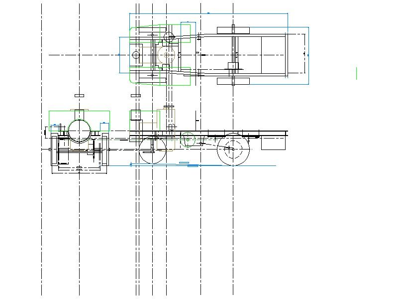
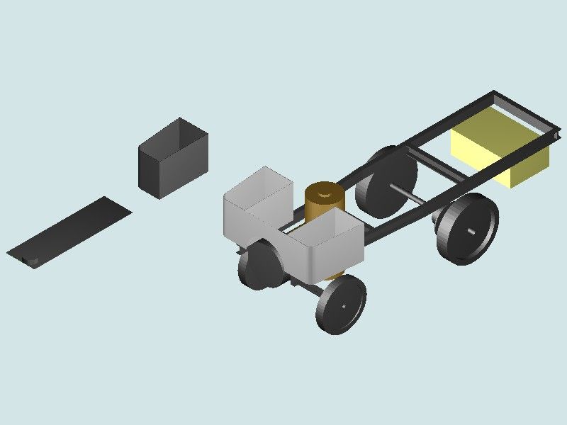
Participant@nigelgraham2I hope the drawings below, produced in TurboCAD 19 Deluxe, help explain my points.
I hope too, no-one thinks I do not realise the value of CAD. I do, but while most people use by their choice and own approach to how they – not it – design what they make, my choice is limited by how to use it, not by why.
'
Martin –
I am sorry but you are mistaken here:
" I'm not seeing any intention of you wanting to learn. "
Wrong. I have every intention of wanting to learn – I already knew what CAD offers; but I had not realised it is so hard to become sufficiently proficient! If I had known that in advance, I would not have bought it.. Anyway, is it wrong to be honest and admit failure?
' ' '
The pictures represents my level after hundreds of hours' trying to teach myself what many others must find easy to learn to high level, in much less time.
'
My original question was from my trying SolidEdge (CE) as an alternative to TurboCAD. I knew if I made reasonable progress, there are people here and in my club to offer help. It seems few in model-engineering use TurboCAD, but I have just updated my edition to TurboCAD 2021-x64. Siemens web-site offering SolidEdge tutorial videos deterred me with terms like "synchronous" in describing the videos supposedly for beginners. It implies needing much existing CAD knowledge, suggesting the material is for professional users moving from other makes. I had hit a wall of unintended technical exclusivity.
'
The drawings: Of my 4"-scale steam wagon chassis essentially as it is now, minus the enclosed vertical engine not yet made but which will stand behind the boiler and between the crew seats. I have omitted the seats and the chimney, for some reason, though I have made them. The flywheel shows as the green circle in the elevation.'
The orthographic colours are by Layers; which I find help differentiate sub-assemblies, and too see details under them.
The bunkers proved very difficult to draw as open-topped boxes with floors. The yellow block is of course the water-tank, sheet brass. The two chassis rails are of heavy channel-section; drawn by Extruding rectangles into cuboids for thickness / depth, Assembling and Adding them into cohesive units. Since the chassis necks inwards for the steering, making one rail needed nine cuboids!
Putting the bits together used both Assemble tools and co-ordinate sums – I know the latter should not be necessary; and I saw SE does not show a grid and co-ordinates, by default.'
I probably used "primitive" (library) cylinders for the boiler, smokebox, the differential with its chain-sprocket (not the true shape of the modified BMC unit, nor the sprocket teeth); rear axle, wheels. '
The front axle is really an I-beam. Each wheel is really a pair of dished, rose-pierced steel plates in a thick wooden rim and shrunk-on steel tyre. The radius-arms, springs and Ackermann steering are also fitted but like the wheel details, too difficult to show in 3D. I don't yet know where the chain and 2-speed gears will lie in the chassis: a typical task for the 2D drawing.'(Shrunk-on: 30 minutes in the oven at Gas Mark 9, then wiv' a big 'ammer! Many Edwardian factory staff photos include a bloke with a sledgehammer.) '
I did not make it from many drawings, certainly no CAD ones. I made these drawings from it. Perhaps that will explain that I am the designer – sort of – not the pencil or computer. Although the 3D picture has no practical value, these two drawings represent firstly, what I have already "designed" and made, and secondly, my level of skill with CAD.
I wanted taking up CAD to facilitate the project, with me still as designer ! All my mistakes, revisions and re-makings are by me. The software won't necessarily stop that, but might help me make the revisions and corrections before wasting more metal and electricity in the shed.
8 May 2022 at 11:54 #597424Nick Wheeler
Participant@nickwheelerOnce again, your approach is causing your problems. We keep saying that you need someone to show how any of your parts could be produced using a program you already have.
As we showed in a previous thread, your chassis rails are not nine separate operations each, but two simple, editable sketches and another editable procedure. Then you create a mirror of it for the other side. That makes you the designer, with the computer as a tool.
Coordinates are another deadly trap: let the computer use the features on the parts to position/align/join them. You won't assemble the real thing by moving the boiler back 30.56583mm and up 23.9 from the front crossmember and ground, but shift it until the mounting holes line up.
The elevations you need(I would prefer want, but I suspect we work differently) are then taken from the model because it already has ALL of the information. You can create as many as you need, showing the whole machine, separate parts or how sub-assemblies relate to each other. Again, that's being the designer.
Your 3D model is the CAD equivalent of a back of an envelope sketch, which is then used to start the design and figure out how you're going to do it – the traditional drawings of complex parts weren't created by just grabbing paper and pencil and drawing away. A considerable amount of training, practise, experience and thought was used first.
8 May 2022 at 14:32 #597439 John HinkleyParticipant@johnhinkley26699
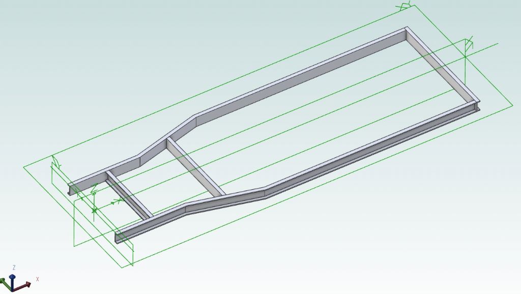
I have to agree with Nicholas Wheeler above, in that it appears that your basic approach is flawed. I find the drawing in your last post extremely crowded and difficult to read, possibly exaggerated by the scale. However, to prove, at least to myself, a relative newcomer to Alibre Atom, that a reasonable stab at it could be made, I devoted a whole half-hour to drawing up the following to illustrate how it could be done:
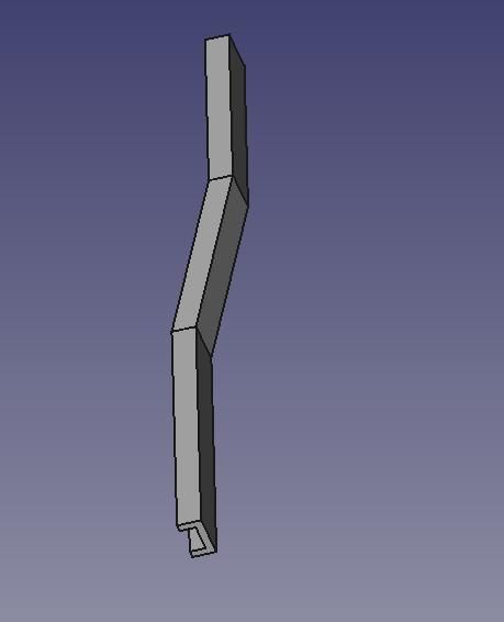
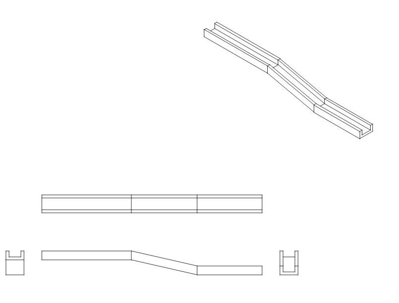
From the top, the shape of the chassis side rails, offset from the centreline by the appropriate dimension. (I had to guestimate the values, of course.) Next row: the cross-section of the rails, then sweep the cross-section along the side rail shape and then mirror about the centreline.
Third and forth rows, the cross members. That's the individual parts. Make an assembly and using constraints, align the parts to form the complete chassis, thus:
In this way it is possible to build up the whole model from the separate parts as you would in real life. Rightly, or wrongly, I have got the impression that you are trying to produce the 3D model all in one go from an orthographic projection. Correct me if I've got the wrong end of the stick..
Sorry to have taken up so much space. I really am trying to help.
John
Edit: Just noticed that I've missed a crossmember out – but you get the idea,
Edited By John Hinkley on 08/05/2022 14:33:44
8 May 2022 at 19:05 #597476lee webster
Participant@leewebster72680Hi Nigel,
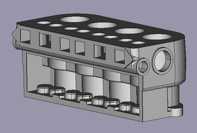
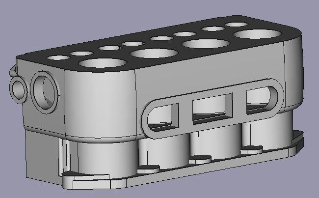
When I started with 3D cad 3-ish years ago it took me months to get something worth the effort. I was using FreeCAD then and managed to produce this model of an Austin 7 engine block.
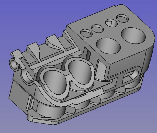
The next image is a "cut away" view of the block internals, internals I might add that play no part in the casting process. My mistake to include them in the design. I am learning!
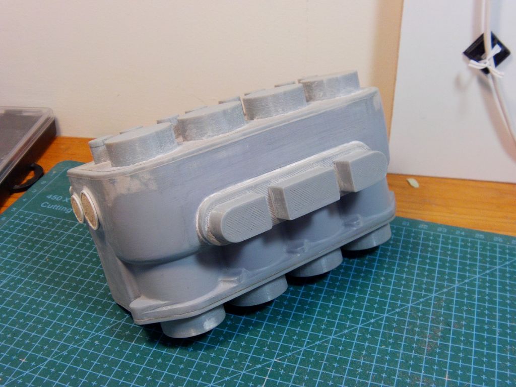
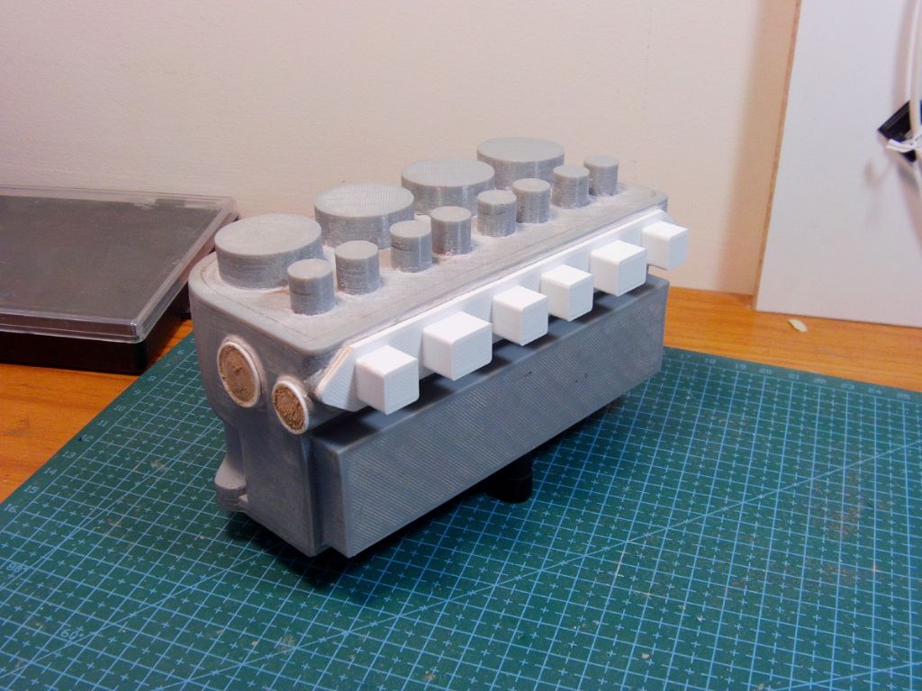
And then I 3D printed it using an Ender 3.
The 3D prints will be used as patterns to cast the parts in aluminium, I can't cast iron with my set up. If you have no strong need for 3D, don't bother with it. Stick to 2D if it suits your needs. There is no way I could have produced these models without 3D cad.
Lee
8 May 2022 at 22:37 #597494Nigel Graham 2
Participant@nigelgraham2Thank you for your help:
Nicholas –
Finding a tutor is the hard part! Short of very expensive courses a long way from home and not feasible for me.
TC does not use the term "sketch", and in the edition I used at least, those cranked channels can only by built up by adding separate entities. All ways came down to that approach. Thinking about it, I probably assembled only one length of channel from 3 cuboids, then made copies for the other 3 parallel to an axis.
The central portion being cranked meant I could only build it up separately from three rectangles, starting with a line joining the corresponding vertices on the parallel sections – which in turn can only be set by entering grid offsets. Using rotation would have entailed calculating the angle, but probably not accurately enough to work (i.e. pixel-on-pixel).
From a straight section of channel it was easy to rotate a copy of appropriate length by 90º, then copy that, to make the three cross-members. (One is in the cranked portion, its ends angled to suit, to support the back of the boiler, footplates and eventually the engine. No. 2 is just ahead of the back axle, No.3 across the rear end.)
As you say, the second longitudinal was a mirror-copy, and that was straightforward.
I know you are supposed to let the computer do the calculations but TC allows co-ordinate moves; and I use them when I should not, for assembling entities to each other. That is because I find TC's 3D assembly methods so hard. Simply mating two vertices is fairly easy, but otherwise needs fiendishly difficult "Reference Point" manipulations. (I don't know if other CAD systems use Reference-points: an object's RP is by default the centre of the plane area or of space the object occupies but can be moved to, typically, a 3D object's surface to give an assembly snap-point not on a vertex. )
Using co-ordinate and distance entries lets you place easily, objects at points not fully identified by others. For example, the cylinder representing the differential on that representing the axle: assemble the diff co-axially to the end of the axle, then enter the appropriate dimension to push it along the shaft. If you can't move the RP to help you do that, the only option is co-ordinate sums – but I do know TC hopes you don't need do that!
(When I tried using SolidEdge, I managed to drawn a concentric rectangle and circle, but found nothing to place the circle or copies of it elsewhere at set distances within the rectangle. I noticed too that the rectangle was a set of separate lines, not a closed polygon. And that in 2D!)
'
John –
Ah, well, that shows how radially different are Alibre Atom and TurboCAD!
You show the Alibre version of TC's "Model Space" – the drawing area – is a planes-frame floating in an infinite nothingness. Solid Edge seems similar. TurboCAD lets you display a grid instead, optionally inch or metric, to which you can set the drawing – using the Grid Snap, I normally put the major centre-lines on the main axes. In 3D your default view is "looking down " obliquely on the grid, in its (x, y) directions.
I could not see how you produced that channel cross-section; nor how you produced it along the full length, bends and all.
TurboCAD has a "Sweep" command, but I have never used it, and do not know what it is for. It is sometimes mentioned in the Users' Forum Gallery by users describing how they made some exquisite 3D image; and appears called "Rail Sweep" – hardly intuitive!
The drawing looks crowded because it is greatly shrunk to fit here; and contains many centre-lines and dimensions that do not show as such. However, I did not produce the 3D image from that. I don't think that is possible (in TC) anyway, and I drew it entirely from new.
Anyway, I would want the opposite – producing the orthographic workshop drawings from the 3D model. I think TurboCAD does offer that, but I don't know how.
Lee-
That is very impressive! 3D printing and CNC machining are obviously beyond me, and beyond my means, but I admire what can be done with them.
2D suits most of my needs, and is necessary for the workshop drawings, but I had wanted to be able to use 3D CAD mainly for assembly-drawings; and at least I have that option.
I have used 3D CAD for a non-engineering task: the diagrams for a caving-club journal article I wrote, explaining the nature of geological faults. I had to use only black-and-white, with hatching, to represent strata; and one part puzzled me for a while. In white-only, it kept appearing as a cavity. Once I realised I had to "colour" it white, it worked fine.
8 May 2022 at 23:06 #597496blowlamp
Participant@blowlampI made a video using rectangles to create a simple symetric version of a chassis similar to yours, without needing to mirror anything.
It uses the sweep tool that you haven't tried yet.
Martin.
Edited By blowlamp on 08/05/2022 23:08:11
8 May 2022 at 23:28 #597497blowlamp
Participant@blowlampI've also had a go at your bunkers. Started with a rectangle and shaped it to suit. Extruded, then Shelled to leave an open top container. Finally Mirrored to make a pair.
Martin.
8 May 2022 at 23:49 #597499Nick Wheeler
Participant@nickwheelerI've never moved anything using coordinates. It's the CAD equivalent of measuring off a print and hoping that everything works out OK.
Your 'hard to manipulate reference points' are what the computer provides to save you the calculations. A differential would have the reference point(Fusion calls them joint origins, and they can be vertices, edges, faces, hole centres, additional points or any other feature) where the centres of the pinion and ring gears meet. Or the pinion flange. Maybe one of the halfshaft flanges if you're weird. You would then use a relevant joint type to place that to your axle centre line. The joint function also allows you to offset it in any of the three main axes, and/or rotate it around them. So you could initially set the pinion angle, and skew the axle across the frame if you were modelling a Renault
 . And alter either angle when something else changed.
All these programs will display grids on planes, and the main axes. They also allow you to turn them off which is preferable.
9 May 2022 at 11:46 #597557SillyOldDuffer
Moderator@sillyolddufferPosted by Nigel Graham 2 on 08/05/2022 22:37:36:
…
TC does not use the term "sketch"…
…
I know you are supposed to let the computer do the calculations but TC allows co-ordinate moves…
When I tried using SolidEdge, I managed to drawn a concentric rectangle and circle, but found nothing to place the circle or copies of it elsewhere at set distances within the rectangle…
TurboCAD has a "Sweep" command, but I have never used it, and do not know what it is for.
… I would want the opposite – producing the orthographic workshop drawings from the 3D model. … I don't know how.
Once I realised …, it worked fine.
Don't get hung up on 'Sketch'! Although TurboCAD seem to have built 3D on top of a full-function 2D drawing tool, in effect you are doing Sketches, which are a type of 2D drawing designed for making 3D objects, with 2D functions stripped out and others added. I suspect TC's 2D editor has led Nigel into the mire by mixing 2D & 3D functionality.
Coordinates are best used sparingly. Real wagons are built from connected parts, each fixed in some way to another. Ditto 3D CAD: models shouldn't be a shower of independent bits made to look OK by flying in close formation! Coordinates are simple at first, but cause big problems later.
Rectangle/circle positioning is solved in SE by drawing construction lines just as in 2D. FreeCAD is the same and I expect the others work that way too.
Sweep exists to solve bent girder type problems. They make a solid by running a profile along a 'rail'. Example is FreeCAD, but F360 and SE are similar.
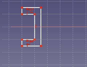
1. Sketch the U beam profile on the XZ plane:
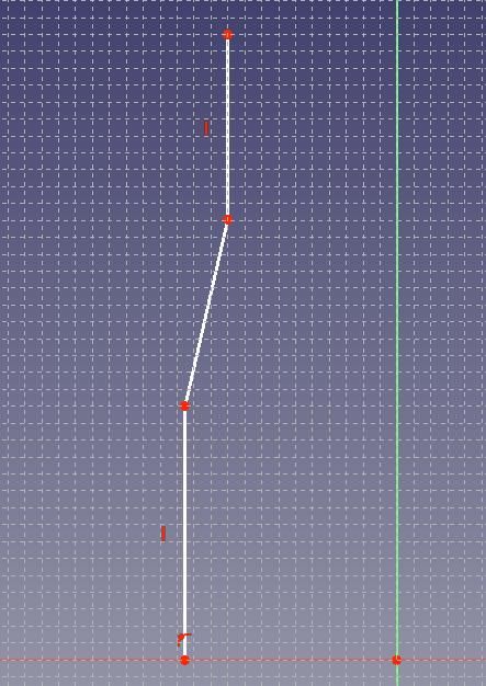
2. Open another Sketch on the XY Plane, and draw the length and sweep of the U-Beam:
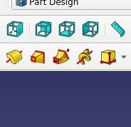
3. Select both sketches and click the Sweep button, yellow & red centre.
All being well, the U-Beam will appear:
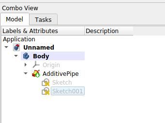
Not bad, but wrong – the sweep line is incomplete! No problem, looking at the History I see I've created a 'Body' consisting of an 'AdditivePipe' based on two sketches. One sketch contains the profile, the other is the sweep line. Within reason I can change both.
The missing line is added to Sketch001:
Closing the sketch redraws the sweep:
No dimensions yet- it's all been done by eye, correct shape, but not size. Generally best to add dimensions and other constraints as soon as they're known, but they can be deferred whilst the design is fluid. However, the model isn't finished until constraints have been added, and missing them can cause trouble. A later change might cause unexpected movement. Planned moves are wonderful, unplanned moves are annoying.
Best practice to give sketches and parts meaningful names in the history rather than the defaults:
In FreeCAD everything depends on what was done before; history. It can cause bother if an early step is adrift. SE's Ordered mode is also history based, but it also has a 'Synchronous' mode, allowing models to change irrespective of the history. Speeds development up, but can cause confusion. Then Ordered Mode is better. Solid Edge recommend learning Ordered mode first.
2D drawings are generated last from 3D models. Third/first angle are tick-box choices, the hard part is deciding what to dimension and caption etc, which is done with the mouse. Sections are easy. FreeCAD, SE, and Fusion are similar.
'Once I realised … it worked fine.' sums up my learning experience. Nigel rejects the idea he has a 2D mindset, but I recognise the symptoms: I had it too! Perhaps the hardest part of learning 3D-CAD was unlearning a mass of earlier 2D ideas. 2D brings a blizzard of unhelpful preconceptions about how 3D should work. Nope! The operator has to adapt!
Dave
9 May 2022 at 12:14 #597563Nigel Graham 2
Participant@nigelgraham2I think we've hit a snag: radially different CAD packages!
I have not given up entirely on trying to learn 3D CAD but the gaps between my attempts are becoming longer.
Everyone else here is using programmes other than TurboCAD, and those do the same things in very different ways! So I am reading here how others use methods not existing in TurboCAD, to draw the same things. Let's look at what I mean…
TC gives several options for creating plane figures and "solids" _ but the solid figures are in more than one form, with peculiar properties, and this is partly why it is so hard.
TurboCAD floats the image and plane-indicators against a grid (options include inch/metric and non-display). The 3D default view looks obliquely down at the grid: isometric, as the view-angle tool says. You can of course rotate objects to any angle in any plane.
This allows aligning major centre-lines or outlines to the origin, axes and grid; and placing objects by Snaps and/or co-ordinates and direct dimensions. So if I place an object at typed-in (1, 1, 1) from the origin or some other point, I know its Reference-Point will be (1.000000000, ditto, ditto) from that datum. If I then use the Copy tool appropriately, I know its offspring's RP will be at typed-in (x, y, z) translation or Aº rotation from its parent, again at n.0000000… accuracy. (You can also set you own co-ordinate origin, and definite angle or count-round increments.)
The RP in TurboCAD is the centre of the object's plane or spatial occupation: the dead-centre of a cube or sphere, on the centre of the long axis of a cylinder or prism. For an object not fully symmetrical, such as my chassis rails, it lies outside the object itself.
Using this RP correctly can be vital for 3D assembling parts other than by handy Snap points like vertices and edge-midpoints, but I find this very difficult. Luckily TC is flexible: allowing Assemble Part B to A by Vertex Snap, Move B across A by dimension-entry change, as accurately as above.
My error is not in using numerical values. TurboCAD expects numerical entries where necessary as it often is of course. Entering numbers allows for example, fitting parts along a shaft or across blank facets (surfaces); but I am using them where I need not, or should not. .
By trying to do the computer's work for it, a drawing that may look right by eye can hold tiny value errors preventing other editing tools from working at all. It took me a long time to learn that in drawing a plane figure from scratch rather than editing a "primitive" or by the Polygon-tool, I need Snap the lines together so the polygon can be filled (e.g. coloured, or cross-section hatched), copied, moved, extruded, etc. If one corner fails even invisibly, the extrusion is a wall of display-line thickness, not a solid.
To draw those bunker walls, I copied-in-place the outline to a very slightly smaller size – tricky on a non-rectangle and with a quadrant corner – and extruded both. The line thickness filled the gap. I see now I should really have extruded a Poly-line with one wall fractionally shortened to stop the figure closing. For its companion, I used mirror-copy or rotated a straight copy 180º. These are the only ways available in TC.
Incidentally, Nicholas, no half-shafts and gear geometry here. This wagon's axle is of traction-engine type, with the differential on through- and cannon- shafts; necessitated by using chain-drive.
The diff itself is a modified, ex- front-wheel-drive car unit, with a motorcycle sprocket on the crown-wheel's place. Consequently the datum-plane is that of the chain centre-line; not among the gears. The correct form is of the differential one the wheel, also traction-engine pattern; but I made the axle so many years before finding a photograph that shows this detail that it can damn' well stay like it!
.
I may try 3D modelling again, after a long break. For I need re-design the cylinders – machined from stock bar – as I made basic mistakes that some 20 years after I bored them, are now causing all sorts of unforeseen problems like studs penetrating steam-passages, and nowhere sensible for the valve-chest steam inlets!
9 May 2022 at 12:32 #597565blowlamp
Participant@blowlampTurboCAD is dreadfully poor compared to more modern offerings
Did you check out the two videos I made on the previous page, of how straightforward 3d CAD (MoI) can be?
I did your bunkers and your chassis in about seven or eight minutes – only approximations of sizes, but just to show the principle.
.
Martin..
Edited By blowlamp on 09/05/2022 12:34:59
9 May 2022 at 12:39 #597566Nigel Graham 2
Participant@nigelgraham2To answer Dave (SOD….)
Looking at your version of those cranked channels….
Yes, a very different package but the idea that TurboCAD might have made its 3D mode an extension (extrusion?) of its 2D had never occurred to me. Though I am worried how to use it, not how it was written.
I could have extruded the basic section from a "polyline" rather as I think you have – perhaps did, I forget now – and I am not sure that this shows much difference in difficulty and work between the two systems. If I could have used TurboCAD more efficiently that's by me, not its designers.
To make that channel section in TC there are two or three alternatives, all probably of similar effort. I did not try going the whole hog with root radii and tapered flanges!
+++
How did I bend the steel itself? It is 50 X 25 X 25mm HRS channel, the nearest to what appears on the ancient photos that are my only source material; but probably of over-scale thickness.
I have access to a manual bender really intended for forming narrow-gauge track rails, and used that to chalk-lines and wooden straight-edge on a concrete workshop floor, finally measuring the rails back-to-back, by steel rule to ensure parallelism more importantly than absolute displacement I can adjust for. I doubt the originals were much more sophisticated!
The I-beam front axle consists of 2 lengths of folded 2mm thick sheet-steel channel welded back-to-back, dressed flush and cut to width. The channel was second-hand from I know not what, but very close to scale by the photos. (And I must have been better at welding than I am now!)
9 May 2022 at 18:11 #597617lee webster
Participant@leewebster72680I think there might be a flaw in your attempts to draw in 3D. I recently commented on a youtube video where an A7 enthusiast is building an A7 replica racing car. I asked what CAD package he was using, it looked so bad at 3D I couldn't believe it was meant to do 3D. It was Turbocad. He slaged it off with a very choice swear word and finished by saying he was too old to try anything else. I was 65 when I started to use FreeCAD, and like A7 man, I found TC to be the biggest load of wossname I ever tried. Sling it over the nearest hedge and set yourself the task of learning Solid Edge or FreeCAD or MOI or use a crayon and draw on a piece of slate. just don't try to use TC.
Turbocad is the present you give to someone you hate.
10 May 2022 at 00:31 #597657 PatJParticipant@patj87806
Someone above mentioned how intolerant 3D programs are to the slightest imperfection in a 2D sketch.
This use to stump me in the beginning, and I forgot how big a problem it use to be for me.
If you are not snapping exactly to the endpoints of lines and such, then you can have tiny imperceptible gaps that can be difficult to track down and eliminate.
One way to avoid the gap problem is to over-draw every line, ie: draw the lines longer than they need to be, and then use the trim command to cut them off, thus ensuring none of the dreaded gaps.
Sometimes the trim command itself creates a problem, such as at the intersection of two curved lines. The trim command can produce a small section of arc on top of another line; and this stops a 3D program in its tracks.
Solidworks attempts to show you where the problems are in a sketch, but that feature is pretty ineffectual.
I draw 2D sketches that are intended for 3D very carefully these days.
Even then I sometimes have sketch problems.
One method for determining where sketch problems are is to draw a straight line across half the sketch, and trim it off. If the problem vanishes, then it is on the side of the sketch that was trimmed off.
You can narrow down a problem area somewhat quickly using this method.
Another method to salvage a sketch is to go back and extend all the lines over each other, and then trim them all off again.
This usually clears up the problem.
A 3D program treats a sketch as a boundary, or a fence.
If there is a gap in the fence somewhere (no matter how small), or two lines where there should only be one, or one line on top of another, or a line projecting out by itself beyond the fenced boundary, then the program cannot make the calculation required to create a 3D solid.
Another way to visualize it is to think of a piece of string that has the ends fused together, so you have a continuous loop. You can place this loop of string on a drawing board, and move it into an number of shapes (no overlapping shapes). As long as the string is not broken, and does not overlap itself, the program will work.
A sketch must be a complete, clean, non-overlapping, continuous boundary.
.
Edit:
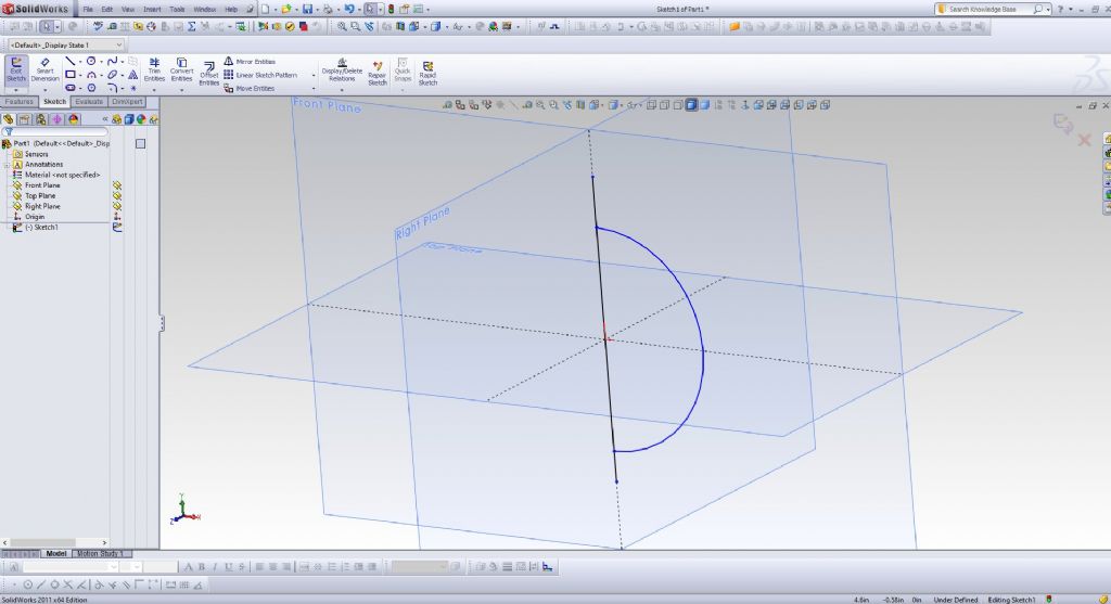
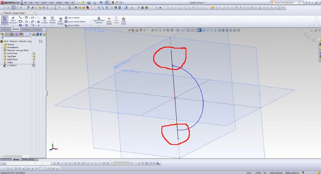
Another trick to diagnosing sketch problems is to temporarily cock the 2D sketch into an isometric position.
This is very helpful in exposing stray unintentional lines that are stopping the program.
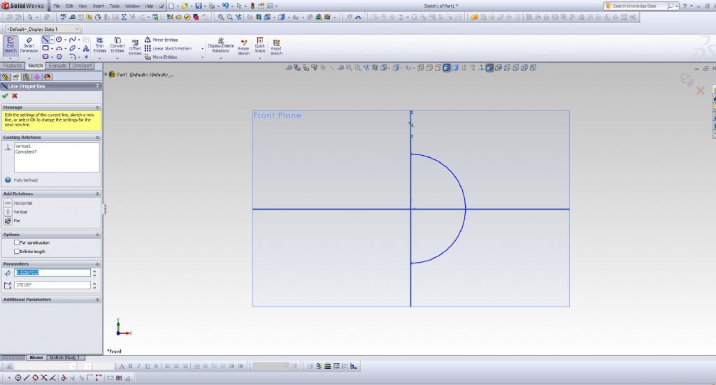
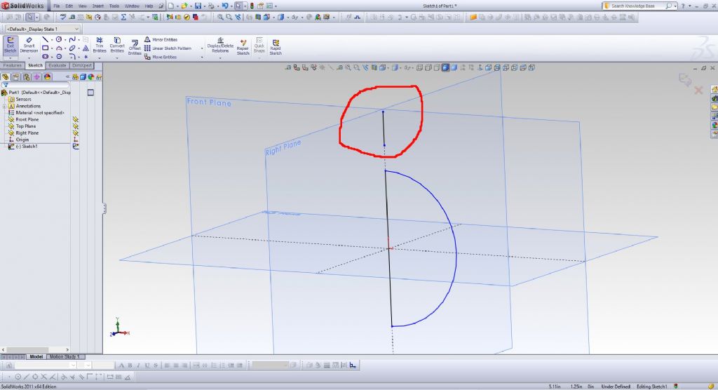
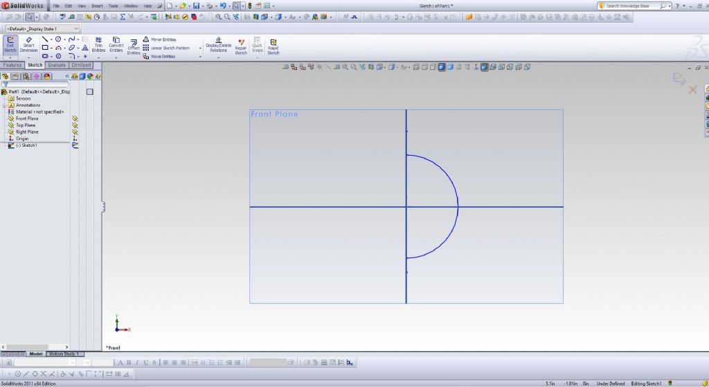
I will attach a couple of examples, where I added a stray line segment up above my sketch, and another example where my vertical line extends beyond the circle.
It is much easier to see these problems with the view cocked over into isometric.
Edited By PatJ on 10/05/2022 00:54:55
10 May 2022 at 02:48 #597662Nigel Graham 2
Participant@nigelgraham2Martin –
I'm afraid I'd not seen the videos but to be honest, while I am grateful that people are showing how they can draw the same parts as I'd done, they are using systems I do not know. I examined Dave's offering carefully, but was a bit lost because he refers to concepts and terms I have not met.
I have SolidEdge (CE) on my computer, but found it impenetrable.
Lee –
I don't want to get into merely slagging off programmes because I don't know how to drive them so they produce the very sophisticated work possible with them. I doubt that car enthusiast knows either, but is afraid to say so!
The TurboCAD Users' Forum Gallery is a huge collection of beautifully-rendered engineering and architectural images – including cars – showing its, and its expert users', capabilities. Far beyond what Mr A7 and I can do, but though TurboCAD has its faults and is difficult, it is he and I, not TurboCAD, at fault. Though any CAD package is hard to learn. They are designed for professional draughts-people fully trained, at great expense, to use them.
' ' '
I agree with you and Pat about boundaries around figures: it took me a long time to learn that!
' ' '
PatJ –
I have found if you are not careful, in TC at least, heavy copying, trimming and other editing without sufficient skill or care can create many line fragments and complete figures like circles, stacked below the visible ones. These can be very frustrating because TC doesn't know which one you mean. Fortunately, the pointer reveals them all, so you can weed out the dross.
' ' '
This illustrates the sheer difficulty I have using TurboCAD – NOT a judgement of the software as it was all my fault. I describe the steps I took, and the results, because clearly, I was doing things wrongly. I was not using the "wrong" programme.
I have just spent about 3 hours trying 3D again, using my engine's cylinders cut in cast-iron bar, not cast as cylinders. I need revise what I have part-made, due to problems I could not foresee.
I drew the basic block then tried to draw the covers: two discs, different diameters (compound); with a common sector cut off between the cylinders; a shallow boss on the inside face, shallow recess in the top, 6 stud-holes in each including that shared, bisected by the common cut-off. A fairly common feature, bringing the cylinders closer together.
Two overlapping sets of three concentric circles, like a Venn diagram. The cut line joins the circles' intersections. The stud holes, as circles. All still plane figures.
Trim the main outline circles to shape. Move one set a short distance away (TurboCAD makes co-ordinate and distance moves easy).
Join the arcs and cut-lines as polylines ( mind the "gaps in the fence" ) , extrude all plane shapes as required. Those generating the stud-holes project above and below, so subtracting these "dowels" leaves holes.
The recesses and bosses were fairly easy. Adjust their generating extrusions vertically from the common surface; subtract the upper ones to create the recesses.
The stud-holes cylinders were right so-and-sos though. I lost two and had to generate new ones, using temporary construction-lines to find their centres as the covers are now unsymmetrical.
Then one refused to play nicely at all; and I must admit this does hit TurboCAD quirks that are so hard to understand. I have mentioned previously that TurboCAD has at least three classes of 3D solids, each with odd characteristics. One is that if you try to alter its height, it moves up or down instead of growing or shrinking. This happened with one of the holes, making it impossible to generate it properly.
Then I "lost" one of the locating bosses – accidentally deleted. I generated a new one but chivvying it into place necessitated trial-and-error numerical moves as there were no points to which it could be snapped, and I do not know how else to have done it.
Finally I thought I would put the covers above, not on, the block – exploded diagram.
I gave up, with problems insurmountable…
First is the sheer difficulty of moving two semi-symmetrical objects in three dimensions from where I had drawn them, to other places in free space. Snap tools cannot help because those rely on defined points.
Secondly, strange events like the co-ordinates' origin no longer matching the grid axes; something I have seen occur previously. Possibly because I had switched to a facet work-plane and might not have switched it back.
Oddest was what happened to the main block.
I was trying to draw it to be made from a piece of cast-iron too narrow for plain use (giving down to 1/8 inch LP cylinder wall), so sandwiched between steel slabs which would also carry the outer cover studs and possibly the transfer passage. I had drawn and assembled the block and plates. Now, the two plates had risen vertically, like wings, to the top edge of the central block – yet I'd not touched them! Another work-plane error on my part?
.
I abandoned it, but could neither save the file first, nor did TurboCAD warn me to do so when I pressed the closing 'X'.
Well, well…
I have just tried re-opening TC. It launched straight into that drawing apparently at some auto-save point a little before I closed it. I have now saved it properly. So not lost!
And the two steel plates were back as they should, suggesting some setting had reverted to default.
' ' '
So don't let's get into name-calling that at which we may not be experts…
10 May 2022 at 07:15 #597667 JasonBModerator@jasonb
Those covers should be such a simple job if the first circle you draw is placed at the crossing of two axis you can then use the third axis as the centre.. Locate all other parts using that centre or simply a concentric constraint.
As for stud holes any half decent program will allow you to draw just one hole and then use a circular pattern to get six equally placed about the above mentioned ctr,
I drew the cylinder about a year ago to show how it can be done and probably the covers too back don't have time this morning to look back.
With your reluctance to watch videos or find online written manuals any software will be a slow learning process as you are blindly fumbling along rather than finding out how to make best use of what you have be it Turdbocad or any other sofware.
-
AuthorPosts
- Please log in to reply to this topic. Registering is free and easy using the links on the menu at the top of this page.
Latest Replies
Home › Forums › CAD – Technical drawing & design › Topics
-
- Topic
- Voices
- Posts
- Last Post
-
-
New member looking for help
Started by:
 manfromthemist
in: Introduce Yourself – New members start here!
- 10
- 22
-
1 July 2025 at 01:59
Oldiron
-
Twin Engineering’s heavy mill/drill quill removal
Started by:
Martin of Wick in: Manual machine tools
- 6
- 7
-
30 June 2025 at 23:33
James Frankland
-
Bearing boxes for ball race
Started by:
Paul McDonough in: Beginners questions
- 8
- 14
-
30 June 2025 at 22:43
Stuart Smith 5
-
All things Beaver Mill
1
2
…
8
9
Started by:
Robert James 3 in: Manual machine tools
- 42
- 205
-
30 June 2025 at 21:14
Mark Rand
-
IME Watchmakers lathe
Started by:
Greensands in: Manual machine tools
- 4
- 5
-
30 June 2025 at 20:29
bernard towers
-
2 Machine lights
Started by:
modeng2000 in: Workshop Tools and Tooling
- 2
- 5
-
30 June 2025 at 20:15
modeng2000
-
Firth Valve Gear
Started by:
Andy Stopford in: Traction engines
- 7
- 15
-
30 June 2025 at 19:58
Andy Stopford
-
Wiring up a single phase AC motor with 4 wires
Started by:
ell81 in: Beginners questions
- 6
- 8
-
30 June 2025 at 19:49
Howard Lewis
-
M type top slide conversion??
Started by:
jimmyjaffa in: Beginners questions
- 4
- 8
-
30 June 2025 at 19:37
Howard Lewis
-
New (old!) member
Started by:
iansoady in: Introduce Yourself – New members start here!
- 3
- 3
-
30 June 2025 at 19:30
Howard Lewis
-
Request for a Slot to be Milled in a Shaft
Started by:
James Alford in: Help and Assistance! (Offered or Wanted)
- 7
- 12
-
30 June 2025 at 19:04
Craig Brown
-
Meddings MF4 Manual
Started by:
Richard Kirkman 1 in: Help and Assistance! (Offered or Wanted)
- 9
- 17
-
30 June 2025 at 16:11
Richard Kirkman 1
-
FreeCAD v1.0 tutorials
1
2
3
Started by:
 Michael Gilligan
in: CAD – Technical drawing & design
- 12
- 51
-
30 June 2025 at 15:40
Speedy Builder5
-
Boiler Design – issue 4765
1
2
…
7
8
Started by:
Charles Lamont in: Model Engineer & Workshop
- 26
- 178
-
30 June 2025 at 12:58
Paul Kemp
-
High strength 4mm steel?
1
2
Started by:
iansoady in: Materials
- 20
- 31
-
30 June 2025 at 10:55
JohnF
-
What Did You Do Today 2025
1
2
…
6
7
Started by:
 JasonB
in: The Tea Room
- 32
- 172
-
30 June 2025 at 07:37
Diogenes
-
cutting cams
Started by:
bricky in: Help and Assistance! (Offered or Wanted)
- 4
- 14
-
30 June 2025 at 06:54
 JasonB
-
Cookies
Started by:
 Michael Gilligan
in: The Tea Room
- 4
- 4
-
29 June 2025 at 21:42
 Fulmen
-
Multi Cylinder Radial Engine.
Started by:
ebeneezer in: I/C Engines
- 3
- 5
-
29 June 2025 at 20:24
 JasonB
-
Clarkson MK3 t&c grinder
Started by:
Gerd Vanhaevere in: Manual machine tools
- 5
- 7
-
29 June 2025 at 19:07
noel shelley
-
Offen screw type telescopic gauge.
Started by:
Graeme Seed in: Workshop Tools and Tooling
- 3
- 7
-
29 June 2025 at 18:41
bernard towers
-
Tell ‘Em Straight! (Anti-virus sellers)
Started by:
Nigel Graham 2 in: The Tea Room
- 3
- 3
-
29 June 2025 at 13:35
Andrew Crow
-
Sanjay’s Banjo Engine
Started by:
 JasonB
in: Stationary engines
- 3
- 4
-
29 June 2025 at 10:05
 JasonB
-
My experiences with an ELS lathe
Started by:
David Senior in: CNC machines, Home builds, Conversions, ELS, automation, software, etc tools
- 9
- 17
-
29 June 2025 at 08:59
Diogenes
-
TurboCAD Snaps and Dimensioning?
1
2
Started by:
Nigel Graham 2 in: CAD – Technical drawing & design
- 8
- 36
-
28 June 2025 at 18:30
Nigel Graham 2
-
New member looking for help
-


