New technology in Model Engineers Workshop
New technology in Model Engineers Workshop
Home › Forums › Model Engineer & Workshop › New technology in Model Engineers Workshop
- This topic has 152 replies, 43 voices, and was last updated 14 February 2015 at 04:50 by
John McNamara.
-
AuthorPosts
-
31 May 2011 at 16:40 #69465
John McNamara
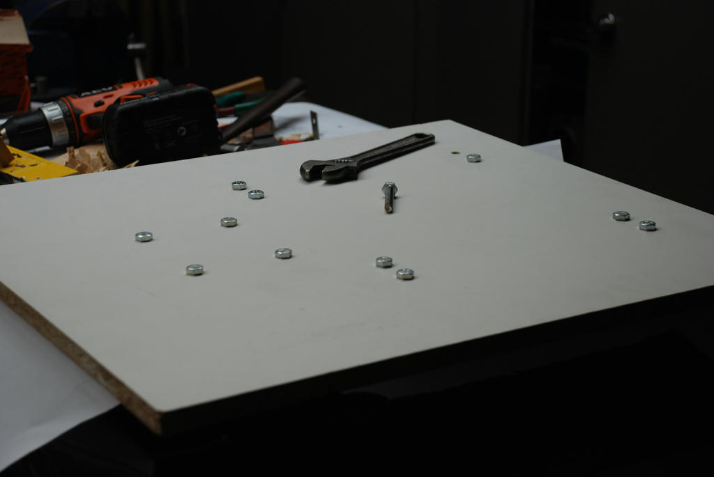
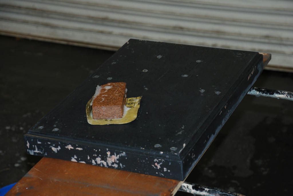
Participant@johnmcnamara74883Hi allI stripped the rest of form work today, it came out cleanly, with a few blemishes now patched with epoxy filler it is ready to paint.The PVC tile bull nose strip that was used to create the edge detail did not stick to the epoxy and was saved. The detail is only there for aesthetic reasons, it does make the base look a lot more interesting than just a rectangular chunk.Next time I am going to use a different formula for the gel coat Using the much thinner Megapoxy H spayed on. to avoid disturbing the release coat.First the M8 bolts that held the inserts in position while casting were removed.After patching… a good rub down with wet and dry paper and water.A quick test for flatness, very pleasing The base was cast on a piece of melamine coated MDF that was sitting on my surface plate on parallel cleats to clear the machine screw heads. about .002 inch error under the straight edge. There will be no problem setting up the rails. Note the inserts half covered by the straight edge.Edited By John McNamara on 31/05/2011 16:51:08
31 May 2011 at 19:08 #69471KWIL
Participant@kwilJohn M, With all the griping about new technology or absence of it, why the waste of Forum space and not an article submitted for publication to a wider audience?
31 May 2011 at 21:00 #69483Hugh Gilhespie
Participant@hughgilhespie56163‘John M, With all the griping about new technology or absence of it, why the waste of Forum space and not an article submitted for publication to a wider audience?’Hmm – Well for me, I am enjoying this posting very much. It is very refreshing to see someone trying new techniques and documenting the results very well. Surely this is exactly the sort of thing that should be encouraged on this forum. Just my twopennorth.Regards, Hugh1 June 2011 at 02:58 #69508John McNamara
Participant@johnmcnamara74883Hi All
Hi Kwil
With the almost incomprehensible size of now multi terabyte hard drives storage space is no longer an issue. Information is never wasted as long as there are others that may find it useful.I have considered preparing an article for the magazine; maybe in the future.
At the moment I just want to “get on with it”,Posting live has the advantage of spontaneity; you are not tied to a publication date and the inevitable delay before the article hits the reader. Every day I discover an issue that must be overcome, or a new idea to improve the work comes to mind.
I know there are others following this thread over 3000 reads so far, very humbling and encouraging; it inspires me to do better. Hopefully a few readers will be encouraged to try the process, and share their findings.
Hi Hugh Gilhespie
Thank you for your note of encouragement.Cheers
John McNamara
Edited By John McNamara on 01/06/2011 03:02:41
Edited By John McNamara on 01/06/2011 03:03:03
Edited By John McNamara on 01/06/2011 03:03:15
Edited By John McNamara on 01/06/2011 03:03:49
1 June 2011 at 06:58 #69511John Stevenson 1
Participant@johnstevenson1Thank you John M,I for one am also following this with interest, my questions are genuine questions of interest.The 3,000 reads also proves that there is an interest in new technology.One thing that came to mind is that my nephew is into kitchen and bathroom fitting and I have scrounged offcuts of very thick 50mm or so worktop that has the same melamine finish for work benches and shelves.I would image that that is also very stable as a base for larger projects. Another thing is or local garden centre also stocks all fancy aggregate for paths and beds, some of this is quite small, 5mm or so and in a lot of cases sharp which I’m sure would be better then the smooth pebbles as mentioned before.I look forward to the next instalment.John S.1 June 2011 at 16:20 #69542John McNamara
Participant@johnmcnamara74883Hi John SIt is not easy to get a definitive answer to the properties of MDF In your case laminated both sides with melamine or the like.I think the issue here is the deflection properties of MDF not the yield (Breaking) strength.I am sure you could place your bench top pieces between two supports and jump on them without breaking them. (Don’t try it just in case)As is often the case in machine design it is deflection not strength that determines selection of the appropriate section. For each application you have to determine the accuracy you require.Damping is another issue. will there be any resonance effects, or vibration. particularly from a low density material like MDF.The link below shows MDF to have a Young’s modulus of 4 GPaAluminium 69GPaSteel 200 GPaThe lower the number the greater the deflection will be.Check the properties of other materials too.An excellent tool that only costs 14 euros is MITcalc for simple beams. for non Structural engineers (Like me) very useful indeed.It is a simple spreadsheet that graphs deflection and yield, for many different materials and many commonly available sections or you can define your own. It takes about an hour or two to become fluent with it. Note how it shows results in red where the material properties are exceeded.As a caveat while you can use it for beams used in building construction, it is not a replacement for a qualified engineer where human safety is involved.I agree re the aggregate. Particularly if there is a clean and (Dry) local source.From my reading most are using granite or quartz. otherwise they use synthetics…Aluminium oxide Silicon carbide Etc.CheersJohn MEdited By John McNamara on 01/06/2011 16:31:35
6 June 2011 at 08:44 #69783John McNamara
Participant@johnmcnamara74883Hi All
It’s been a while since I posted, a busy week here.
The design has had a few modifications.
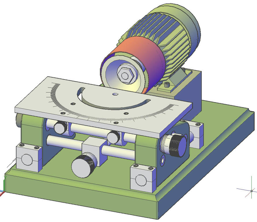
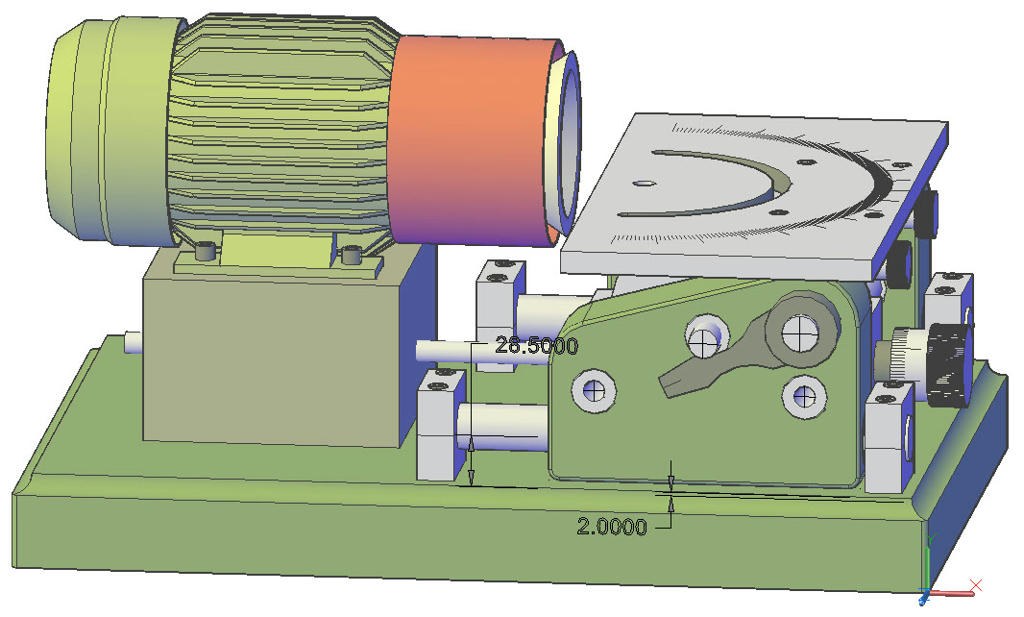
Firstly the end support castings have been lengthened to 170mm and the location of the various shafts changed.
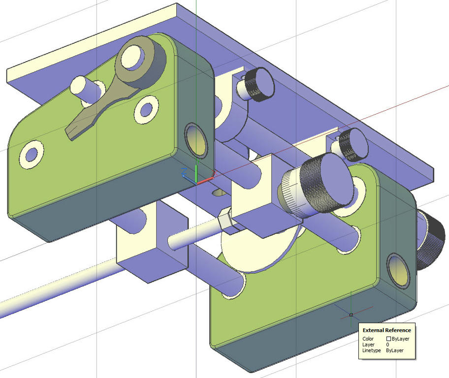
Provision has been made to shift the table laterally a total of 70mm 35mm each way from centre. I plan to have a fine adjustment for the lateral position similar to the Quorn – this is yet to be finalised. I am wrestling with the table angle indicator, the difficulty being that if the table moves sideways the angle indicator should not.
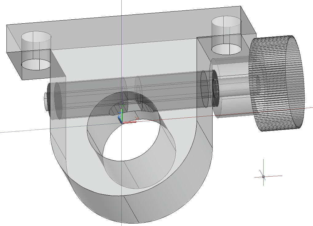
As shown below the clamping for the table is finalised; rather than using set screws that inevitably marr the shaft I have used self centering brass pincer collars. The outer one is threaded, the one closest to the knurled knob is not.
Additionally I plan to make it possible to shift the motor to one side when the motor pillar is finalised, it appears likely that many times the edge of the wheel should be near the centre of pivot.
I would be very interested to hear from MEW members who have built the Worden and use it. Is there ever a need to rotate the motor?
The adjustment knobs for both X and y turn an M12 * 1.75 shaft. There are 70 divisions on the graduated sleeves. There should be 68.8976 divisions for exactly fo .001 inches per graduation mark. I rounded to 70 divisions because it divides by 70 and 10 for the graduation marks to cover one rotation of the shaft.
The Y Axis thread should be reverse threaded to make it intuitive, easy enough to turn on the lathe. The nut (In the motor base), will be cast in epoxy so no problem making or sourcing a special tap.
Making the end support castings
Starting out with a flat base of melamine MDF, onto which a 1:1 printed copy of the side elevation plan for the parts was placed. this paper plan was then protected with “Baking film” a product suggested by my wife, it worked well : the epoxy did not stick to it.
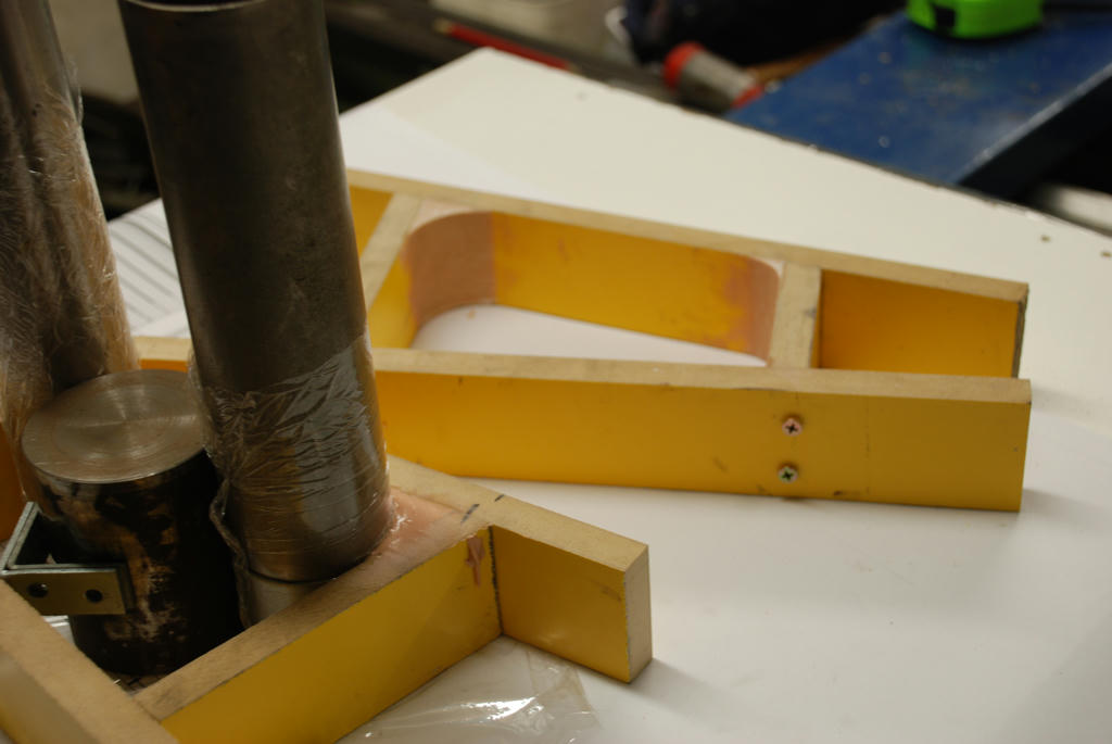
Using this layout, a simple tray mould to contain the mix was cut and aligned carefully with the plan, using 50mm strips of melamine coated MDF.
This left the radiused corners. To form these, odd lengths of pipe I had to hand of the correct radius were used as formers. One was a little small so I wrapped a few layers of tape over it to bring it up to size. I also wrapped cling film around the pipes to stop them sticking to the epoxy body filler.
It was a simple matter to fill the corner with quick setting body filler then press the former (pipe) into the corner and wedge it. Some material squeezed out. The top was trowled off. The material squeezed out along the sides was not touched. After about 15 minutes the mix was “gel” set (still soft). The formers were removed and it was a simple matter to remove the still soft excess material. The small corners were simply trowled with a piece of rod to form the 6mm radius. After an hour the inside of the mould frame was sanded ready for casting.
I used PVA glue as a mould release applied neat, rubbing it in thoroughly with my finger, and when that was set I greased the sides as well. The base of the mould had already been protected as noted above.
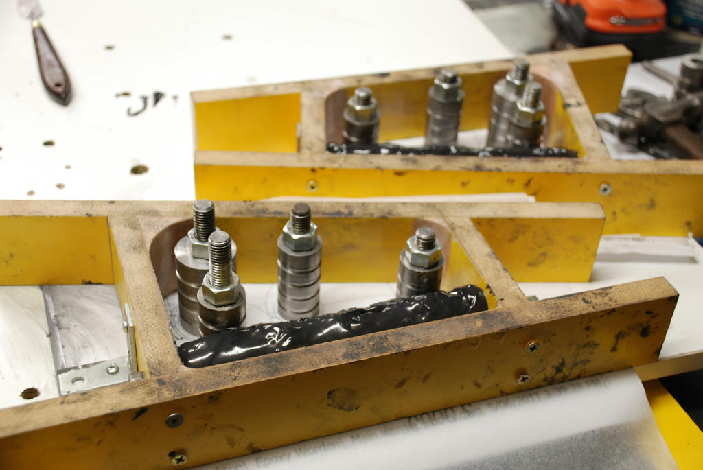
It was decided to cast the Y axis bearings in situ using the Epoxy bearing material I developed previously.
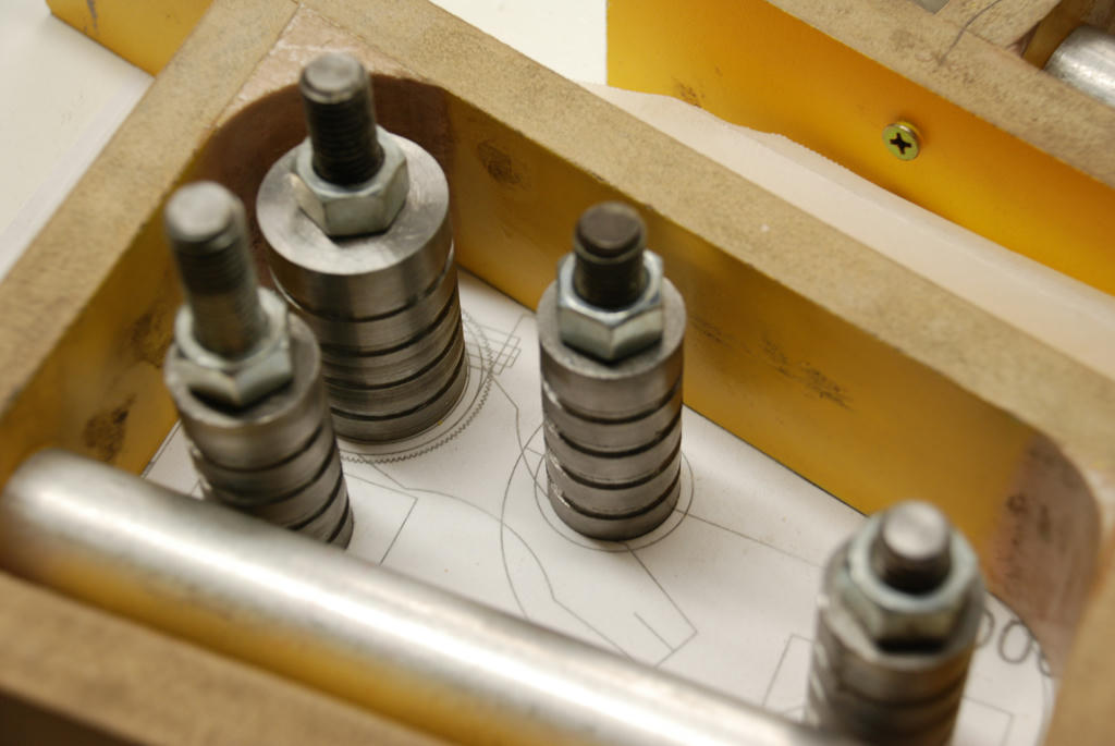
Two pieces of rod cut to 170mm were tapped both ends to enable them to be carefully centered in the mould and clamped. Before the main cast these rods were greased and coated with bearing material. There is a difficulty here….The material tries to run off. I had to turn the casting for an hour before it started to gel. A heat gun would be handy here. It would reduce that time to 15 minutes or less.
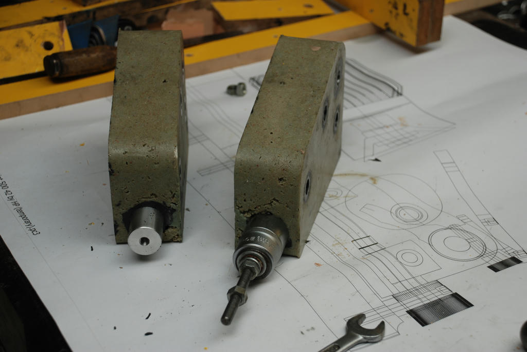
A fair amount of force was required to remove the rods when the cast was set. I used a handy socket and a piece of M8 threaded rod to break the initial grip, once started using a punch (being careful not to touch the bore), the rods were driven out. Upon inspection the bores are shiny. Currently we have a heavy push fit. I will ease the bores slightly for a light push fit. I am guessing about .0001 inches will do it. After the casting has fully hardened over the next week it can be done.Mild steel inserts were made from bar oddments I had to hand,
Leaving a 60mm length sticking out of the chuck I skimmed the OD, center drilled, drilled 12.5mm, faced, grooved with the parting tool and parted off in one setting.
There are 3 x 25mm and 1 by 35mm diameter inserts for each end casting.
The 12mm holes were made to enable the inserts to be securely bolted in position.
The next step will be to bore the inserts to the correct diameter on the mill.Cast mix
1620 ML of oven dried fine washed sand
600ml Megapoxy HICB, normally used in rotary rock crushers (it contains about 60% fine silica powder), therefore our mix contained approximately 16.21% epoxy by volume.
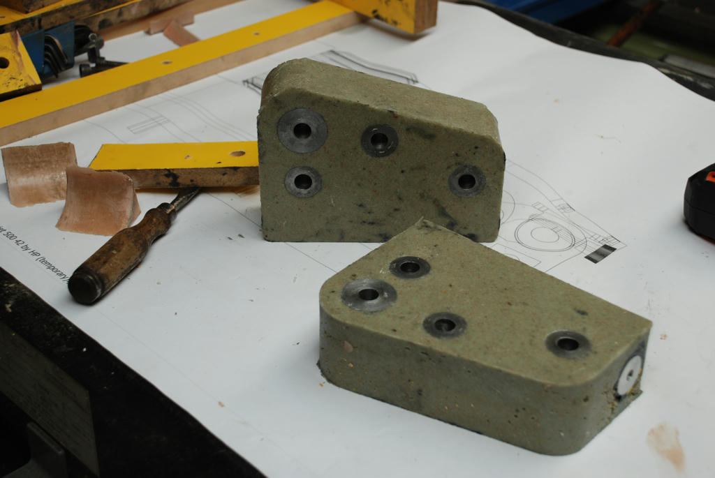
A similar result could be obtained with plain epoxy and graded sand. The mix was a friable mass rather stiff. As shown in the photos we got a good casting with few blemishes. Not quite enough tamping to fill the voids that will need be attended to next time.Finishing
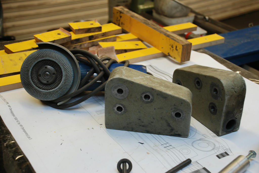
As removed from the mould there were sharp corners and a few blemishes. A small hand grinder was used to remove the sharp corners and form the small radius edge abounding each side. It also made short work of tidying up any raised blemishes. The wheel used was a rather old flap wheel that had seen better days. Maybe this was an advantage as it was not as aggressive as a new wheel would be. There are a few blemishes that will be repaired prior to painting.Continued next post…
Edited By John McNamara on 06/06/2011 08:45:13
6 June 2011 at 08:51 #69784John McNamara
Participant@johnmcnamara748836 June 2011 at 09:07 #69785John McNamara
Participant@johnmcnamara748836 June 2011 at 09:15 #69787John McNamara
Participant@johnmcnamara74883….From previous postBearing former rod pulled6 June 2011 at 10:05 #69789Steve Garnett
Participant@stevegarnett62550Posted by Keith on 20/05/2011 13:31:41:Perhap this country has lost its innovators, hence we are going down hill!
I think that there may be a lot of truth in that. One of the things that has been noted in the past about the people who were truly innovative is that the vast majority of them had what could only be described as an ‘unorthodox’ education – in other words, they weren’t at their formative stage shoved through a curriculum primarily intended to educate the masses, and one that only encourages certain types of rigid thought process.What this meant for people like James Watt (early education at home by his mother, didn’t attend grammar school until much later) was that they could have ‘what if’ thoughts that weren’t constrained by a load of stuff that they’d learned by rote and never questioned. If the only education that you feed to people is based on the present national curriculum, is it really any surprise that we have no innovators of the type we used to?So I don’t think that it’s quite the way ady described it, but I think he’s pretty close when he says that Governments have interrupted the true course of Darwinism! Oh, and Darwin was another one with an unconventional educational background, as well. And there are loads more household names in the same category too.(I should also say that I’m not in the slightest trying to distract from John’s very interesting posts – it’s just that when I read through the earlier part of the thread, this bit stood out.)Edited By Steve Garnett on 06/06/2011 10:08:33
6 June 2011 at 12:22 #69797ady
Participant@adyWe can still do stuff nowadays, but it’s best done in secret.There are far too many busybodies and government/council stasi around nowadays, a natural progression in a society which acquires more money than sense.The more money a society has the more irritating-zero-wealth-creation-busybody-jobs a government generates.The difference between the UK and the Republic of Ireland is a real culture shock to anyone who visits, they can’t afford useless busybodies and it’s just like being back in the good old 1980s.The latest rule to reduce opportunities is banning joe public from entering to buy metal from scrapyards, a real blow in my case because of the huge range of choices which instantly disappeared.For anyone making a prototype bit of engineering this only serves to create yet another barrier.I wouldn’t be in the least surprised to see a law making the licensing of lathes and other larger immobile power tools held in private hands appear at some point in the UK in the future.I recall reading about some British rocket building guys years ago who built a projectile for launching then visited the local cop shop to inquire about any problems with launching a projectile thousands of feet into the air.The advice given was there wasn’t a law against it but could they go somewhere well away from where the public might get bashed on the head when it came down.Nowadays you’d create a major response from multiple government departments.Edited By ady on 06/06/2011 12:37:18
6 June 2011 at 12:57 #69798Steve Garnett
Participant@stevegarnett62550Posted by ady on 06/06/2011 12:22:57:I recall reading about some British rocket building guys years ago who built a projectile for launching then visited the local cop shop to inquire about any problems with launching a projectile thousands of feet into the air.The advice given was there wasn’t a law against it but could they go somewhere well away from where the public might get bashed on the head when it came down.Nowadays you’d create a major response from multiple government departments.Not if you did it properly, you wouldn’t. Just join the UKRA and follow the rules, which are pretty sensible.
6 June 2011 at 13:06 #69799ady
Participant@ady…and slap bang on the front page…..lol============================In addition to this great news, the council is working very hard to
ensure a number of issues raised by membership are resolved and a
couple of exciting project come to fruition this year.Hopefully, within the next couple of weeks, we will be announcing the return of two much missed UKRA institutions.
- The UKRA National Event.
- The UKRA magazine – “10,9,8…”
and
================================Eventually If the council don’t get you first then the insurance liability costs will kill this kind of innovation off forever.6 June 2011 at 14:07 #69801Terryd
Participant@terryd72465Posted by ady on 06/06/2011 13:06:15:………………………………..
Eventually If the council don’t get you first then the insurance liability costs will kill this kind of innovation off forever.Well if a rocket launched in this area misfired and set fire to MY home or car when it landed, I would certainly hope that the rocketeer had good liability insurance.T6 June 2011 at 14:35 #69806Terryd
Participant@terryd72465Posted by Steve Garnett on 06/06/2011 10:05:46:Posted by Keith on 20/05/2011 13:31:41:Perhap this country has lost its innovators, hence we are going down hill!
I think that there may be a lot of truth in that. One of the things that has been noted in the past about the people who were truly innovative is that the vast majority of them had what could only be described as an ‘unorthodox’ education – in other words, they weren’t at their formative stage shoved through a curriculum primarily intended to educate the masses, and one that only encourages certain types of rigid thought process.Edited By Steve Garnett on 06/06/2011 10:08:33
Hi Steve,I agree in part with your sentiment, When I entered teaching from an engineering background I took a course in ‘Creative Design’ at Loughborough university this course produced teachers who could encourage students to think laterally and literally be ‘creative’. Many excellent courses in Engineering and Technology were developed by and for schools to encourage the sort of innovative creativity you are describing. We had a professional body called ‘The Schools Council’ which consisted of teachers, academics and industrialists who suggested and developed suitable ideas, projects and courses. To help fulfil these requirements.However in the 80’s we had a Prime Minister who was anti industry in a big way, and an education minister in the form of Edwina Curry (I joke not). Mrs Curry said that education had to be reformed to get rid of unnecessary outdated content. As an example of this need for reform she was interviewed of Midlands Today when she said that she had visited a school where young students were being shown how to weld, And of course this was ridiculously outdated as all welding was done by machine or robot. She knew that because she had seen it in the nearby Austin Rover plant on a visit. And these comment were by the person who made the decisions!So we got the National Curriculum which we all worked hard to implement but it was changed year on year, huge amounts of work and course development dumped at each change, until the Labour government gave us a breather. The old courses which encouraged knowledge, experience, innovation and creativity were abolished by Ms Curry as was the ‘Quango’ we called ‘The Schools Council’, thus removing professional guidance and leaving Curriculum development in the hands of the bureaucrats and ‘Inspectors’ who wouldn’t recognise creativity if it were stuffed up their backside and ignited.I could have cried in the late 80s and early 90s as the machinery and equipment was torn out of engineering and wood technology workshops and sold to dealers for a song. The workshops were than turned into ‘Blue Peter’ technology rooms staffed by poorly trained teachers.I retired from education a while ago , frustrated by the fact that we were no longer educating young people, but merely getting them ‘qualified‘ with boatloads of GCSEs etc. This is how schools are judged. It matters not whether the students understand or remember what they have learned or whether they are better people, well rounded and educated (in the best sense of the word) or not.I am not optimistic either as the present generation of teachers have been trained to teach to these parameters and the National Curriculum which is generally acknowledged as a failed and expensive exercise.TEdited By Terryd on 06/06/2011 14:42:04
6 June 2011 at 14:38 #69807John McNamara
Participant@johnmcnamara74883Hi All
Just an addendum to the earlier post today post re casting the end plates for the Epoxy Worden; being impatient I decided to accelerate the final cure and placed the parts in an oven at 80 degrees C for two hours. Curing in an oven also produces a slightly stronger casting.
I was impatient to see just what sort of fit will be obtained for the main Y axis guides, and did not want to wait for a week for full cure.
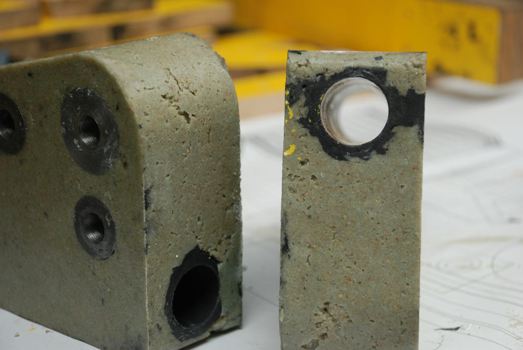
As the attached photo shows I used a reamer; a nice rather old and slightly blunt reamer, that has I have used before for a similar fit; as are many of my tools a find at a local market. I know if used carefully by hand it will not create an oversize hole, it cuts a couple of tenths under. And the spiral flutes give a good finish.
I would not care to try an adjustable reamer here the straight flutes sometimes dig in and you are never quite sure what final finish you are going to get. If I did not have a reamer of the correct size I would have made up a D bit or a lap.
Having reamed the hole, when dry the shaft slides in and out with a small push. With a smear of oil it is very close to perfect, a touch tight, I will let it wear itself in.
CheersJohn
Carefully hand reamed:Just a tiny amount of material removed:Edited By John McNamara on 06/06/2011 14:43:26
6 June 2011 at 16:15 #69813Mike Crawshaw 1
Participant@mikecrawshaw1Hi John,As one of the many readers following your exploits I would like to thank you for an informative and entertaining thread.Although it is highly unlikely that I will ever implement any of the processes you described I have really enjoyed thinking about the possibilities.Thanks,Mike6 June 2011 at 18:37 #69822Steve Garnett
Participant@stevegarnett62550I do like these dual-purpose threads – especially this one, as John rather well illustrates at least one of the other points rather well – I’m pretty sure that the modern education system isn’t really responsible for any of what he’s illustrated!Posted by Terryd on 06/06/2011 14:35:18:I am not optimistic either as the present generation of teachers have been trained to teach to these parameters and the National Curriculum which is generally acknowledged as a failed and expensive exercise.As I’ve been discovering recently, most of the problems are with what they haven’t been trained to do. If you ask them how to develop any new curricula from scratch, they often don’t have the faintest idea of how to go about it. They seem to be curiously deficient in their understanding of the basic philosophy involved – usually to the extent of not even realising that there is one!Unfortunately, it’s going to take a sea-change in enlightenment, and at least a generation after that before we get back to where we were in the 60’s. My recollection is that it was the early 70’s where a lot of the ‘new ideas’ were introduced into teacher training, and I’m afraid it’s been downhill all the way since then.6 June 2011 at 18:55 #69823KWIL
Participant@kwilI agree with Steve, in the 60s when I was developing my industrial and scientific skills, we were taught to think about it, question why and why not. Now they just do not know and as Steve says they do not even know they do not know!
6 June 2011 at 20:11 #69828ady
Participant@adyMy own theory is that British management is amongst the worst on the entire planet.After the destruction of our entire industrial base the present/next generation of amazingly incompetent British managers moved into unaffected areas such as education, healthcare, financial services and government jobs.25 years later we have the biggest banking crisis in recent history, Education is going down the toilet, healthcare is crumbling and those Council/Government guys couldn’t be trusted to run a decent sweetie shop.It’s the youngsters I feel sorry for. They get to pay the price, and it’s a very high price.And it gets worse.Germany, who hung grimly onto their industrial base during the bad times, is now the 2nd biggest exporter of goods in the world, 80 million Germans are exporting more than even 300 million Americans.German exports rise to all time highOnly China exports more than the European nation.
6 June 2011 at 22:31 #69839Terryd
Participant@terryd72465Posted by Steve Garnett on 06/06/2011 18:37:17:I do like these dual-purpose threads – especially this one, as John rather well illustrates at least one of the other points rather well – I’m pretty sure that the modern education system isn’t really responsible for any of what he’s illustrated!Posted by Terryd on 06/06/2011 14:35:18:I am not optimistic either as the present generation of teachers have been trained to teach to these parameters and the National Curriculum which is generally acknowledged as a failed and expensive exercise.As I’ve been discovering recently, most of the problems are with what they haven’t been trained to do. If you ask them how to develop any new curricula from scratch, they often don’t have the faintest idea of how to go about it………………………..Hi Steve,Given that teachers are now trained in about 2 terms of a post grad course with no previous experience, and much of that time is spent on so called ‘teaching practice’ (which bears no relation to the three terms I had to undertake before even being considered) it is a wonder they can be taught anything about the processes involved in education.They may have the academic knowledge from a first degree but that is like giving an engineering graduate a few weeks experience and then trusting him/her with a large project. It doesn’t work.T6 June 2011 at 23:54 #69849John Stevenson 1
Participant@johnstevenson1All our crafts teachers came from industry via a training scheme, as soon as they came from teacher training colleges it all went downhill.
7 June 2011 at 08:07 #69859Terryd
Participant@terryd72465Posted by John Stevenson on 06/06/2011 23:54:04:
All our crafts teachers came from industry via a training scheme, as soon as they came from teacher training colleges it all went downhill.Hi John,I came out of industry and was retrained at a TT college (Loughborough) one of the most highly regarded colleges in the country and had been training excellent teachers since 1927. Many of my colleagues were ex industry and many were college trained. All were very good or excellent teachers. Remember TT colleges were around long before the retraining of ex soldiers and craftsmen, who were also in fact retrained by these self same colleges.Our lecturers at Loughborough were renowned in their fields, several having written what became standard texts, for engineers and woodworkers alike, not just teachers. A good craftsman is not necessarily a good teacher. I have seen many such excellent people try to retrain and fail miserably in teaching, one burly ex toolroom man leaving in tears. Two of the worst teachers I have ever met were ex craftsmen, excellent at their craft but abysmal teachers and they were eventually sacked. I have come across many such cases almost as bad in my years as Head of Department.The problems came with Curriculum changes imposed by the government and more recently with the poor quality of teacher training of post grad students, many of whom do not have the basic knowledge to teach the subject.T7 June 2011 at 08:16 #69860Terryd
Participant@terryd72465Hi John McNamara,I have searched for a while trying to find Megapoxy H over here in the UK as I would like to try the technology you have proposed. However, I cannot find a source and the nearest equivalent I can find locally is almost £30 sterling (46 Aud) for 1 litre. This seems a bit pricey. You did mention in one of your posts that you thought Megapoxy H is available in the UK. Do you remember the reference or the website where you saw it?Best regardsTerry -
AuthorPosts
- Please log in to reply to this topic. Registering is free and easy using the links on the menu at the top of this page.
Latest Replies
Home › Forums › Model Engineer & Workshop › Topics
-
- Topic
- Voices
- Posts
- Last Post
-
-
How To Make A Pressure Gauge Syphon?
Started by:
 MEinThailand
in: CAD – Technical drawing & design
- 4
- 10
-
1 May 2025 at 06:55
 JasonB
-
Dead flies on the front of the car
Started by:
Plasma in: The Tea Room
- 4
- 4
-
1 May 2025 at 06:34
Speedy Builder5
-
Some wild kangaroos over a few days on our Front Door Ring Cam
Started by:
 Blue Heeler
in: The Tea Room
- 2
- 3
-
1 May 2025 at 03:08
 Blue Heeler
-
12 INCH HARRISON
Started by:
john landonbrowne in: Manual machine tools
- 4
- 4
-
30 April 2025 at 22:46
 Bazyle
-
Myford ML10 chuck not revolving.
Started by:
 pothole50
in: Manual machine tools
- 12
- 21
-
30 April 2025 at 22:17
halfnut
-
New member – Nef (from Scotland)
Started by:
nefarious in: Introduce Yourself – New members start here!
- 4
- 4
-
30 April 2025 at 22:13
noel shelley
-
Info on UK Power outage 2019
Started by:
Stuart Smith 5 in: The Tea Room
- 8
- 11
-
30 April 2025 at 22:08
noel shelley
-
Sound effects
Started by:
duncan webster 1 in: Electronics in the Workshop
- 3
- 4
-
30 April 2025 at 20:59
duncan webster 1
-
Dodgy car parts a new low
Started by:
jon hill 3 in: The Tea Room
- 15
- 22
-
30 April 2025 at 20:20
Howard Lewis
-
Help me identify my lathe
Started by:
nefarious in: Workshop Tools and Tooling
- 4
- 9
-
30 April 2025 at 19:49
Howard Lewis
-
Scam email
Started by:
Ian McVickers in: General Questions
- 13
- 16
-
30 April 2025 at 19:45
Howard Lewis
-
Hello from Leicester.
Started by:
 pothole50
in: Introduce Yourself – New members start here!
- 5
- 5
-
30 April 2025 at 19:31
Howard Lewis
-
Superheater pipe repair
Started by:
Colin Reed in: General Questions
- 7
- 7
-
30 April 2025 at 18:27
 Fulmen
-
Warco Machines for Sale
Started by:
my.dad.the.toolmaker in: Manual machine tools
- 5
- 6
-
30 April 2025 at 16:40
 Nicholas Farr
-
Photos
Started by:
petro1head in: Website Questions, Comments, and Suggestions
- 4
- 4
-
30 April 2025 at 15:21
 Nicholas Farr
-
Material Choice
Started by:
 Vic
in: Materials
- 3
- 5
-
30 April 2025 at 13:40
halfnut
-
Selling an Expensive Item
Started by:
Clive Brown 1 in: The Tea Room
- 12
- 15
-
30 April 2025 at 02:01
Chris Crew
-
Warco VMC power feed.
Started by:
Hollowpoint in: General Questions
- 2
- 3
-
29 April 2025 at 20:57
Hollowpoint
-
Anyone know about wells and Victorian plumbing?
Started by:
Ian Parkin in: The Tea Room
- 15
- 23
-
29 April 2025 at 20:48
Martin Kyte
-
moving 150kg+ machines inside warehouse
Started by:
aytact in: General Questions
- 13
- 15
-
29 April 2025 at 18:43
 Nicholas Farr
-
Lathe floor height?
Started by:
beeza650 in: Beginners questions
- 10
- 16
-
29 April 2025 at 17:46
SillyOldDuffer
-
Half Scale 1/4HP A J Weed Engine
Started by:
 JasonB
in: Stationary engines
- 4
- 17
-
29 April 2025 at 17:05
 JasonB
-
Building Bernard Tekippe’s Precision Regulator
1
2
3
Started by:
Chris Raynerd 2 in: Clocks and Scientific Instruments
- 12
- 62
-
29 April 2025 at 16:33
gerry madden
-
Some help with a Cowells speed controller needed.
Started by:
Hollowpoint in: Electronics in the Workshop
- 6
- 14
-
29 April 2025 at 16:24
 Robert Atkinson 2
-
Family tree prog
1
2
Started by:
JimmieS in: The Tea Room
- 15
- 31
-
29 April 2025 at 15:24
JimmieS
-
How To Make A Pressure Gauge Syphon?
-
Latest Issue
Newsletter Sign-up
Latest Replies
- How To Make A Pressure Gauge Syphon?
- Dead flies on the front of the car
- Some wild kangaroos over a few days on our Front Door Ring Cam
- 12 INCH HARRISON
- Myford ML10 chuck not revolving.
- New member – Nef (from Scotland)
- Info on UK Power outage 2019
- Sound effects
- Dodgy car parts a new low
- Help me identify my lathe


