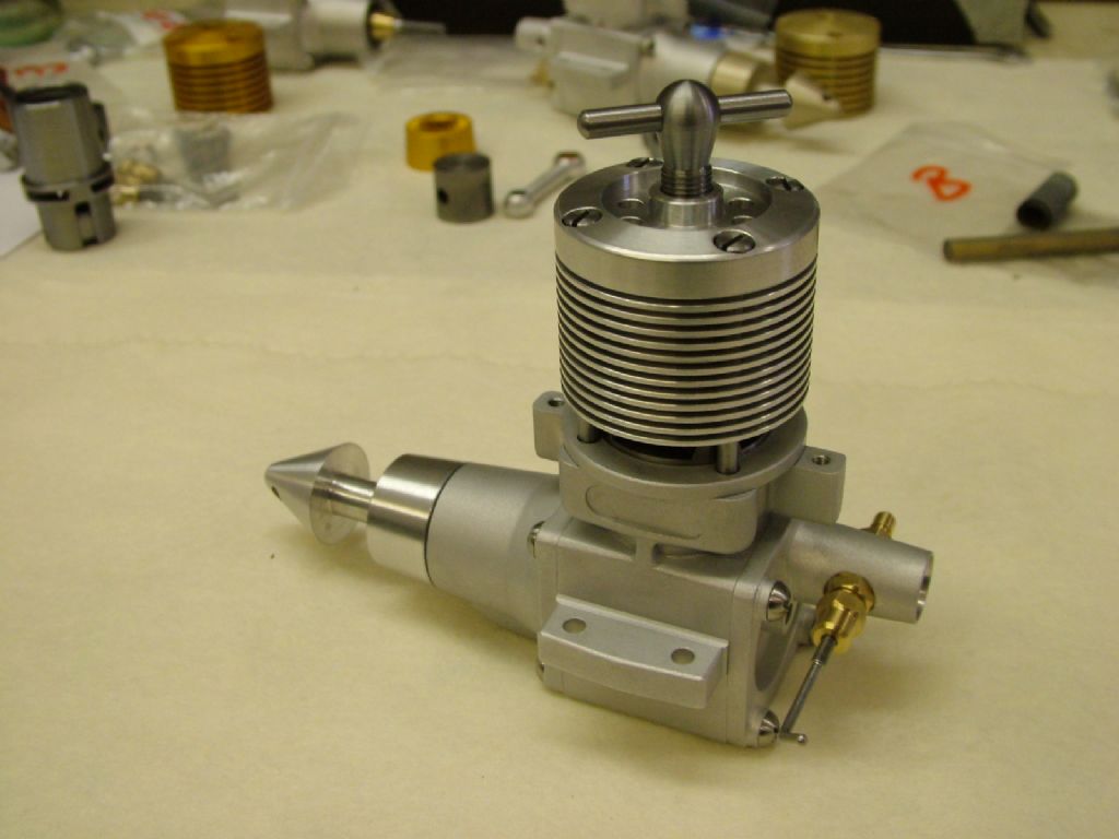
Nalon Viper

Advert

Nalon Viper

Home Forums I/C Engines Nalon Viper

Viewing 25 posts - 76 through 100 (of 144 total)
  • Author
    Posts
  • #442397
    JasonB
    Moderator
      @jasonb

      Ramon, they are not sowing on MEM either as I looked earlier and would have pasted an image from there.

      Advert
      #442398
      Ramon Wilson
      Participant
        @ramonwilson3

        Well that is something really special Emgee but I'm sure you would consider that it's far from the average home model engine builders scope surprise Ceramic balls running in a ground shaft and steel housing is not going to be carried out on the average Myford I guess. Awesome looking product though what kind of rpm and power output are these engines producing ?

        I well remember the original article in Aeromodeller by the Meketmeyer brothers but that was long before I took any interest in making engines myself.

        Looks like Jason is right, things have moved on but I still think that what I do and what Graham and any others with similar interest in making a small diesel require is far more basic. As I read it the inference of John MCs initial post was to suggest such is required for the kind of engines like the Nalon Viper. I find myself at odds with that view – I simply can't see the need.

        In answer to Grahams question about kit all my engines have been made on a Super 7 and an old Linley mill. All bores are lapped not ground which has proved immensely successful – for what I want of it – but the engines you show there are a completely different level and world away from anywhere I have been or indeed from the Nalon Viper that began this interesting foray into modern engine techniques.

        Thanks for sharing the pics and info though – the engineering is indeed very impressivethumbs up

        Tug

        #442400
        Ramon Wilson
        Participant
          @ramonwilson3

          Hi Jason – I can see all images posted on MEM on opening however I have just called a friend who tells me all he can see is the no image logo. (On the Oliver thread)

          I simply can't explain it – all my images are, and have been for years, stored on Google Photos (previously Picasa) and they are all in order as far as I can see.

          I do notice that some folders say shared and others not – I cant find anything so far that lets me 'share' those that aren't but I'm ceratain that this is not something that I have done in the past ie make them 'shared' in order to post.

          Any suggestions welcome as whatever it is has ruined an awful lot of posting if it is elsewhere too – can you see anything on the wide a wake thread?

          Many thanks – Ramon

          #442401
          JasonB
          Moderator
            @jasonb

            It's that same issue you had once before where people just see a no entry sign, Wide Awake is OK. the shared option may be the issue as it is a bit like you have them set to private.

            You could always upload a couple of pics to your album here for the purpose of this thread.

            #442402
            Ramon Wilson
            Participant
              @ramonwilson3

              Thanks Jason – I'll look into it – back later, hopefully with a couple of picssmiley

              #442407
              JasonB
              Moderator
                @jasonb

                Thinking about it a bit more even the Viper design had moved on from earlier engines, just look back at some of the other engines Ron drew up and put into the Motorboy's books – some had the shaft running in nothing more than a hole in the alloy casting and then plenty more with just a plain bronze bush, it is not until the later ones that we start to see ballraces. The Lightweight tether boat engine that I made a few years ago just had plain bearings yet the Stuart literature at the time touted it as "one of the crack engines in speed boat racing" and it probably was back in 1935 and is a world away from the engines that Jim Allen documents on MEM.

                As Ramon says a lot of hobbists who want to make a small IC engine are not looking for performance, most would be more than happy to just have an engine that runs at the end of the construction. Yet others build with the aim to get the best possible performance from an engine and are constantly looking for ways to squeeze that last little bit out. An engine like the Viper is ideal for them as it's not too complicated and not requiring castings also makes it attractive to those doing their first engine or two. Maybe some will get the bug and want to start to develope higher performing engines others may not.

                I certainly fall into the first group and won't really run an engine after I know it actually works, maybe just the odd run with friends and like minded people and at the odd show, putting any of the engines into an airframe, hull or chassis has no appeal to me personally.. In fact on the recent Midget which was again a tether boat engine I even altered the cams and timing to get a slower revving engine as I wanted a nice sound rather than an all out screamer and for that there is really no point in altering the design from the same plain bronze bearings.

                So long as you enjoy your way of doing it that's all that matters.

                #442429
                john feeney
                Participant
                  @johnfeeney58965

                  Hi "Tug"

                  Most of the engines with the` high performance` bearing set up are of 2.5cc capacity and used for class F2C team racing. I think they are of Russian and Ukraine design and manufacture. They are not generally available, although Profi engines are, where price is around $800.

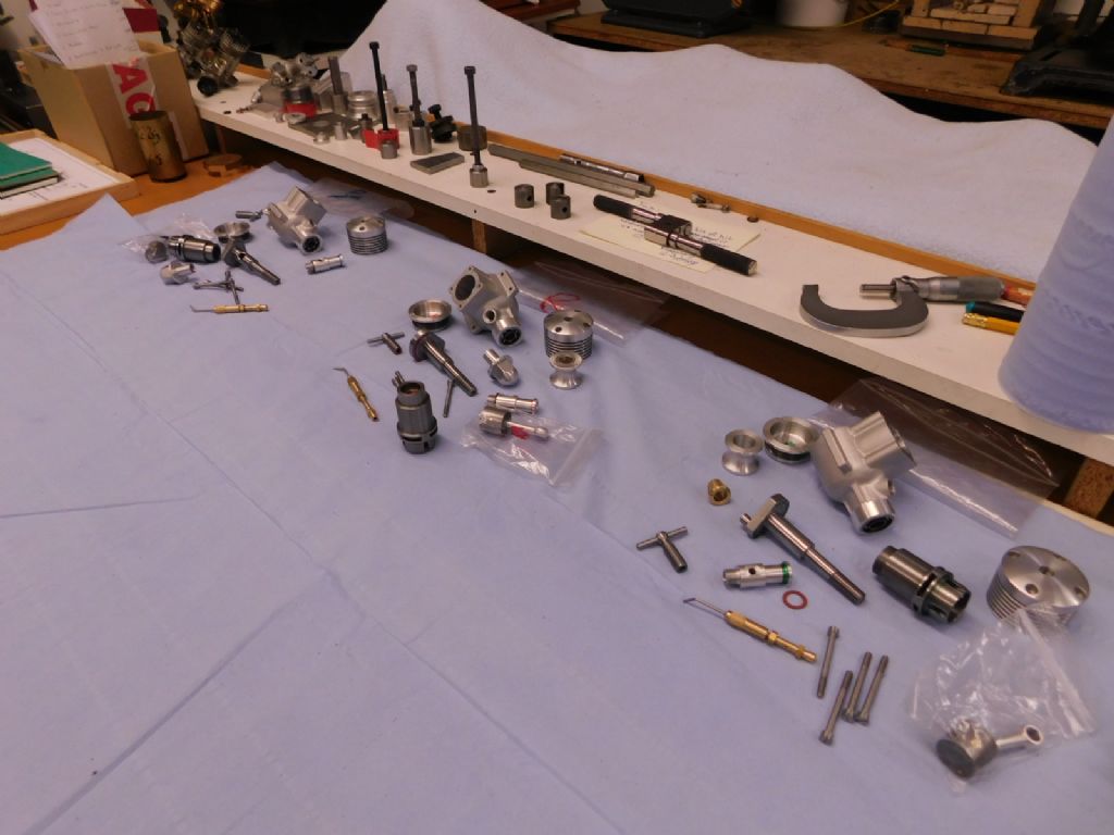
                  My engines( 1.5cc capacity) where designed in about 1980 and originally used a `machined from solid` crankcase. I eventually found an investment foundry who would make castings from `home made wax` dies. (see album photo`s) The top one is the crankcase, the next one is for the soluble wax core, the third one shows the front and rear housing dies. The final one shows a crankcase wax pattern before the core is dissolved, it`s a previous version.

                  I have tried most of the bearing arrangements but not all at once.Currently I clamp the front bearing onto the shaft with the prop.driver. I have run it up 18000/20000 rpm with no problems, power is about 0.3 bhp.

                  There is a lot more involved in these types of engines and I havn`t kept up with their design and manufacture over the last 10 years or so. Mine are basically 1980`s vintage using steel cylinders and cast iron pistons.

                  For most model engineers making an I. C engine the Nalon Viper is a good step up from the side port `Mills` type engine

                  Another one is the Sugden Special, I think plans are available but not sure if the cast aluminium crankcase is available.

                  John Feeney

                  #442454
                  Old School
                  Participant
                    @oldschool

                    John

                    As you say the best F2c engines are coming out of the Ukraine and Russia but these are diesel and the class is fuel limited so not maximum performance a compromise between speed and distance.

                    The all out 2.5cc power class is F2A speed glowplug engine with tuned pipe exhaust systems running with the engines reving around 40,000 rpm and the best one is built in this country BR Irvine engines th Profi from the Ukraine is catching up.

                    #442466
                    Ramon Wilson
                    Participant
                      @ramonwilson3

                      Hi again,

                      Yes Jason, I'm sure that is the goal for most who set out to make a small diesel or glow motor for the first time. I know it was on the Nova that was my first and it has been ever since.

                      All out performance is an entirely different perspective and is not something that I personally seek. That said I do want an engine to run as well as it should and hopefully much in the same vein as the original. A fair example would be the little 1cc Super Tigre compared to the Eta series – at a scaled 5 cc their individual performance is considerably different but still as anticipated.

                      John (F) – Whilst I am aware of their existence I have no knowledge of modern F2c engine make up nor the modern speed engine that Old School describes both of which really are a million miles away from Grahams desire to make a Viper. A high performance engine to me would be of the order of an Eta 15, Oliver Tiger, Enya and Super Tigre 15 diesels and as previously said OPS , Super Tigre etc glows.

                      Thanks for the info on your engine(s) – as said it certainly looks to be a very nicely machined engine with performance to boot. I am intrigued by your current method of clamping the front bearing – is this to allow movement in the rear bearing due to expansion as John MC implies or is the shaft held axially by the rear bearing allowing the front one to move slightly under case expansion – this is the way I set my engines up.

                      Jason – I have finally managed to make all my (relevant) image files as 'shared'. I contacted a friend but his PC was still not showing images on the Oliver thread on MEM. Since then I have rebooted my PC in the hope that might help. If they still cannot be seen then I really do not know what to do next.

                      I have uploaded some images of the Olivers to my album on here ….

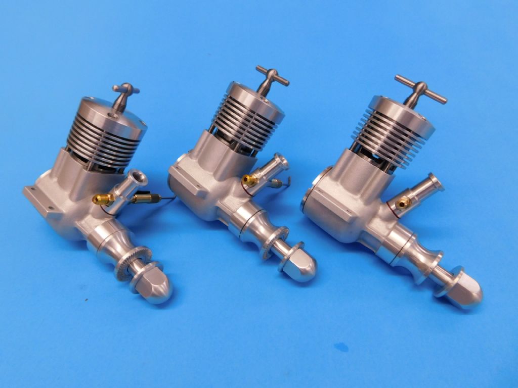
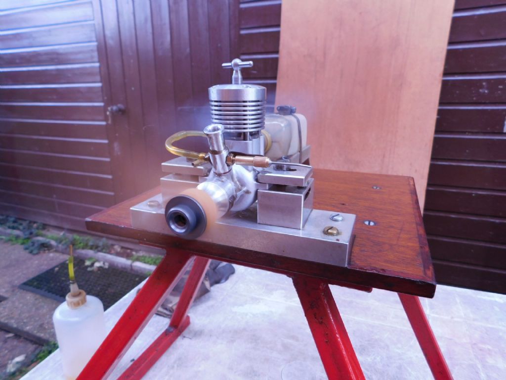
                      These are my latest engines, all machined from solid with cast iron pistons in En1a liners

                      tiger (116).jpg

                      These are identical – the image distorts their height

                      tiger (117).jpg

                      tiger (121).jpg

                      It's been refreshing to discuss these small engines and their manufacture something not too often seen on here these days.

                      Regards – Tug

                      #442626
                      John MC
                      Participant
                        @johnmc39344

                        Some interesting comments but nothing that explains why the correct method for mounting rolling element bearings should be ignored. It doesn't matter if its an engine suitable for a first time builder or the latest very high performance engine, why not do the job properly? In most cases the design will need a little updating, why not to make a better job?

                        The principles have been known for many years, certainly since the Viper was designed.

                        Reading through the FMV engine history, those guys seem to understand the problem of different expansion rates. Not sure their solutions are good, clearly they have not heard of C3, C4 clearances.

                        As for my sketch, thats is what it is, a NTS sketch to show the principle, doesn't matter if there is a flywheel or propeller, principle is the same. As for which bearing (in this application) should be fully constrained, I think it best the bearing nearest the load (prop or flywheel), will be running cooler therefor less likely to want to move. I have suggested a circlip there are other ways of clamping the bearing

                        As for the radial fit of the bearing in its housing, I'm surprised at the somewhat casual approach to it. Again, for a successful installation its important to get these fits correct. Small diameter bearings require some very tight tolerances, always tempting to add a bit more, just in case!

                        Also please note that these well founded principles apply to where ever rolling element bearings are used.

                        My final (possibly!) word on the subject is, if at all possible, in some way acquire a copy of the SKF general catalogue (other makes are available), its all in there.

                        John

                        #442648
                        Roy Vaughn
                        Participant
                          @royvaughn26060

                          John, I can assure you that "those guys" certainly knew of high clearance races, one at least of which is needed for the rear race in an aluminium housing setup. I think in fact they allude to the difficulty of getting same in affordable quantities. Roy

                          #442674
                          Ramon Wilson
                          Participant
                            @ramonwilson3

                            Hello John,

                            As you appear to be insisiting that this method is the only way I can't help but wonder why it is that in all the engines I have ever seen dismantled, either in my hand or in literally hundreds of engine reviews over the years I have never seen any form of spacing between bearings other than the shaft itself. By implication you seem to suggest it should.

                            From a practical point of view it just introduces another part, not only unnecessary but something that would require to be perfectly concentic in order to run with the case bore itself.

                            In my humble opinion, and, in the face of so many that have spent so much time in developing the power of these small engines I assure you it is humble, none have done more than those involved in racing or speed in all genres but for me specifically, control line flying. To dismiss the Meketmeyer brothers in such a fashion and indeed those that followed on sets yourself high upon the bar. Their ideas and articles sharing those views were groundbreaking at the time as was that of Stockton and Jehlik, T/R world champions whose radical ideas using an ETA15d as a basis lead on to Paul Bugl's incredible engines all from which the modern F2c engine developed.

                            Your initial posting and subsequent insistance that this is the 'correct' and by implication the only way leads me to wonder why so many commercial engine manufacturers – certainly in the pursuit of more powerful engines than their competitors – have never adopted this method over the years on what must have been thousands of differing designs – sorry I simply can't see it. I don't disagree with your recomendation per se – just in this specific application.

                            Yes, I may not have an academic background, indeed I was once accused on here of having a, quote 'Monkey see, Monkey do' unquote kind of approach. Well so be it, it has proved to be a viable attribute for me so far. 'Yer pays yer money yer takes yer choice' I guess but I've always been keen to learn from others just always tried to make my own mind up as I see fit about the advice being given. I'm afraid this is one of those occasions I don't share the same view.

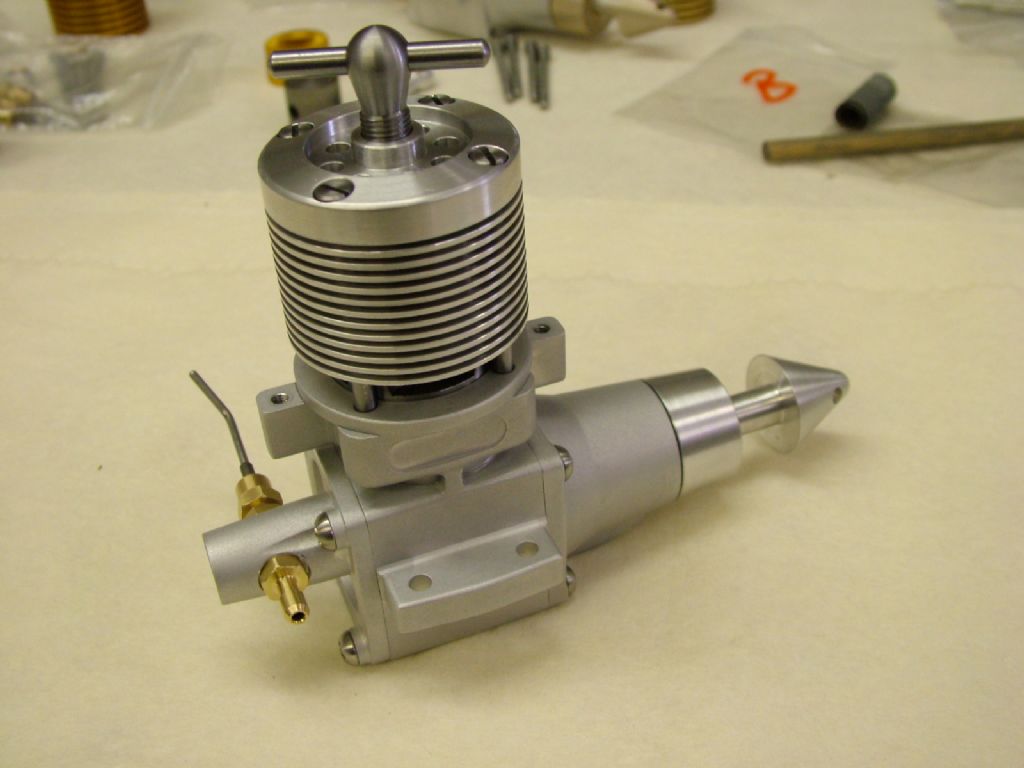
                            Yes, I do have the SKF catalogue along with the RHP one but neither has any info on these small I/C engines (that's TIC by the way) however, to the best of my ability, I do try to fit them with as good a radial fit as recommended in them- heres another example, my favourite of those made so far – another scaled to 5cc, this time the 2.5 cc ETA Elite Mk11

                            dscf3049.jpg

                            dscf3047.jpg

                            On that note I'm afraid we shall have to agree to differ – I will continue as before even if it is 'wrong' – others of course will have to make their own mind up.

                            Seasons Greetings to you

                            Regards – Tug

                            Edited By Ramon Wilson on 21/12/2019 14:06:53

                            #442684
                            Old School
                            Participant
                              @oldschool

                              John

                              Its one solution, if it was as good as you say it would be in use in miniature high performance engines but not everything scales as we would expect.

                              i would be very happy to be proved wrong. As for C3/4 bearings yes they are in the bearing manufactures catalogues but try buying a small quantity no chance.

                              #442713
                              JasonB
                              Moderator
                                @jasonb

                                I suppose one reason a spacer has not become common practice is it rather Bu**ers up any front induction engine as the spacer will block the inlet port in the hollow crankshaft.

                                I suppose the spacer could also be machined to provide the required "open" period but it would need to be keyed to the crankshaft in some way to prevent it rotating out of position and you wouldthen have to fit the front bearing after the rear one, conrod and spacer which is not ideal particularly when it comes to taking the engien apart and trying to extract the front bearing with crankshaft in place

                                #442728
                                Ramon Wilson
                                Participant
                                  @ramonwilson3

                                  Now that's what I call lateral thinking Jason – if it could be moveable then fixed in position as opposed to keyed it could be used to vary the inlet timing positioning smiley

                                  Don't quite see your reasoning in involving the conrod in this and also extracting the front bearing with the crankshaft 'in place' ? – hardly possible I would have thought.

                                  Given that the bearing housings are exactly in line – an important factor of course – I have always fitted the front bearing with an interference fit as close to that recommended that can be acheived with the measuring kit available. The shaft fit on the front bearing is a very light tap fit. The rear bearing is also a light tap fit on the shaft with the outer again an interference fit. The case is heated and the shaft dropped in, lightly tapped through the front bearing and the rear bearing drops into it's housing. Making the shaft tolerances too high does lead to difficulty on disassembly.

                                  As previously mentioned the size of the housings are indeed important but without the correct measuring kit not always easy to establish the kind of tolerances required.

                                  Given that a plug guage will not enter a hole of the same diameter, making a very tightly toleranced and highly polished (and easy to measure) plug guage just under the lowest tolerance size will overcome this issue

                                  The housing is bored very finely until the guage just slips in. Casual? well maybe – but it works – especially if you don't have some pretty esoteric measuring kit to hand and it is tenths involved here and not many of them either way. By making the guage to the lowest tolerance if the housing does prove tight this can easily be eased with a slip of wet and dry paper around 600-800 grit.

                                  It's worked so far for me – it's up to others to decide how best to go about it.

                                  Seasons Greetings Jason

                                  Regards – Ramon

                                  PS I am told the image issue on MEM is now resolved – thanks for the heads up

                                  #442734
                                  JasonB
                                  Moderator
                                    @jasonb

                                    That should have read crankshaft not conrod. My reason for suggesting a bearing would need to be removed was so that the key locating the spacer and the spacer itself could be removed.

                                    Seasons Greeting to you and Sue too.

                                    #442758
                                    John MC
                                    Participant
                                      @johnmc39344

                                      A few points. Wide clearance bearings are readily available in most sizes at only a very small price premium. Its not always possible to do things properly "on the cheap", sometimes spending a bit more money must be done. The exception seems to be C5, hens teeth comes to mind.

                                      The "FMV" article, I've read that again, while they are well aware of the problem, the solutions offered leave a lot to be desired. That was nearly 45 years ago, surely things have moved on since?

                                      JasonB, yes a spacer on the crank would cause a problem as you describe, not insurmountable though. The great thing about forums, in general, is that a solution can be found if only people can get out of the "not designed here" frame of mind.

                                      I was going to share my latest design for a small IC engine that I'm (slowly) building. Not now though, for fear of upsetting the status quo…….

                                      John

                                      #442765
                                      Ramon Wilson
                                      Participant
                                        @ramonwilson3

                                        Thanks Jason – regards from Sue too.

                                        John – I've always believed it possible to disagree without being disagreeable. We are all entitled to an opinion and you have a view – which I respect – but don't share. I've expressed my thoughts and put forward my reasons to support them but please, don't be churlish on my account – no ill feeling is meant I assure you.

                                        Do share your engine design with us, I'm sure there are many who would like to see what you are doing. I have shared all my engine builds either on here, MEM or HMEM and David Carpenter has then taken some of them to include on his MEW website. Though there have been questions over time I don't recall any negativity.

                                        Merry Xmas – Ramon

                                        #442767
                                        Roy Vaughn
                                        Participant
                                          @royvaughn26060

                                          I believe that the current top motor in pylon racing is the MB, also a Rob Metkemeijer design, so it's bearing setup may illustrate the state of the art for front induction motors. I found some maintenance instructions online which give some clues:

                                          http://bmpra.bmfa.org/mb-service-sheet-2

                                          LINK

                                          I'd be interested to know where high clearance bearings can be obtained in one or two off quantities.

                                          Roy


                                          Edited By JasonB on 22/12/2019 10:03:56

                                          #442768
                                          JasonB
                                          Moderator
                                            @jasonb

                                            looks like a fairly similar setup to john's suggestion for the front bearing and although an integral bearing at the rear it may be able to slide (can't really tell from the sketch) in it's housing and being integral there is no need for a spacer.

                                            #442771
                                            Clive Hartland
                                            Participant
                                              @clivehartland94829

                                              Many tears back my two main engines being a Dooling 29 and a McCoy 29 which I used for all of my control line racing. Both had plain crankshaft bearings and I could get 18000 rpm with a smaller prop.

                                              If there was a pile in it was always straight in on the prop and crankshaft which never seemed to bother them, I never bent any crakshafts even on smaller engines. In fact the only damage I did was to an Amco 3.5 which snapped the gudgeon pin which I replaced quickly with a bit of a 1/8" drill.shank. That engine powered a 'Powerhouse FF which had a 5 sec run.

                                              #442772
                                              Ramon Wilson
                                              Participant
                                                @ramonwilson3

                                                Roy – it's been quite a while since I got them but did manage to source some C3 bearings for an Eta 15 S&J build from 'Simply Bearings' – certainly only bought two as I recall

                                                Worth a try perhaps?

                                                The MB engine certainly is a state of the art motor with modern thinking (but still not using a spacer). As said before though a superb standard of machining but I'm sure you'd agree far beyond the scope of the average home builders kit.

                                                Nice to see Metkemeijer spelt correctly – mine was a guess indecision I have some drawings for an engine he designed for C/L aerobatic use which I'm sure feature a similar build process on crankcase design – I'll have look how he has set up the bearing on that.

                                                Regards – Tug

                                                #442777
                                                Emgee
                                                Participant
                                                  @emgee
                                                  Posted by JasonB on 22/12/2019 10:06:46:

                                                  looks like a fairly similar setup to john's suggestion for the front bearing and although an integral bearing at the rear it may be able to slide (can't really tell from the sketch) in it's housing and being integral there is no need for a spacer.

                                                  On the MB the front bearing is locked in with a nut, with the ability to add/remove shims for correct end float of the shaft, using a circlip doesn't allow for positive adjustment.
                                                  To remove the rear outer bearing race requires the case heating to above normal working temp so I doubt it moves in use.

                                                  Emgee

                                                  #442778
                                                  Emgee
                                                  Participant
                                                    @emgee
                                                    double post removed text
                                                     

                                                    Edited By Emgee on 22/12/2019 10:35:45

                                                    #442948
                                                    John MC
                                                    Participant
                                                      @johnmc39344

                                                      I've just read through the service sheet for the MB engine. Like the idea of incorporating one of the inner races in to the crankshaft, a simple solution to the vexing problem of clamping one of the inner races to the shaft.

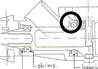
                                                      Why, I wonder, is there any need to use shims to control end float of the shaft? In the area I have circled in the (copied) sketch, if there is a small amount clearance between the case and the bearing the need to him would be eliminated. As a bonus the tolerances on the various linear dimensions associated with the components could be eased somewhat.

                                                      As Emgee has pointed out the heat required to disassemble the engine suggest the bearing won't move in use. What will happen is that the bearing will be able to find its own position during running, therefore not imposing any axial load on its self. The other bearing is doing all the axial location, just as it should be.

                                                      mb engine3.jpg

                                                    Viewing 25 posts - 76 through 100 (of 144 total)
                                                    • Please log in to reply to this topic. Registering is free and easy using the links on the menu at the top of this page.

                                                    Advert

                                                    Latest Replies

                                                    Home Forums I/C Engines Topics

                                                    Viewing 25 topics - 1 through 25 (of 25 total)
                                                    Viewing 25 topics - 1 through 25 (of 25 total)

                                                    View full reply list.

                                                    Advert

                                                    Newsletter Sign-up