Nalon Viper

Advert

Nalon Viper

Home Forums I/C Engines Nalon Viper

Viewing 25 posts - 51 through 75 (of 144 total)
  • Author
    Posts
  • #442009
    John MC
    Participant
      @johnmc39344

      Firstly my thanks to JasonB for pointing out that I am concerned with the axial location of the bearings.

      If the (Nalon Viper) engine could be made exactly to the (poor) drawings I've studied, additional axial load on the bearings due to incorrect constraint of the bearings (over constraint) would be applied as the engine reaches running temperature.

      This would be so very easy to correct and reduce the need for extremely accurate machining. If anyone is interested I will sketch the correct way to mount these bearings.

      This error seems to be a common theme with this type of engine that use rolling element bearings for the crankshaft support.

      Saying that its always been done this way and it works is not a reason to persist with poor engineering design. I've built several small "diesel" engines, those with ball bearings have all needed a small change to bearing mounting to correct what is a fundamental error.

      Also, it looks like the crank disc of the Nalon Viper will contact the outer, stationary member of the adjacent bearing……

      John

      Advert
      #442036
      Emgee
      Participant
        @emgee

        Hi John

        I for one am interested to see your method of machining/fitting bearings in the crankcase of model engines, any improvement to performance is most welcome.

        Isn't it always the case there will be some contact between the disc valve and the crankcase components ?

        Emgee

        #442054
        JasonB
        Moderator
          @jasonb

          John, having just had a closer look at the Viper drawings I tend to agree with you, the forward face of the crank disc is flat and will pull up against the bearing outer, other designs often have a shallow raised area so that only the bearing inner makes contact.

          Also a step is often provided for the taper collet to limit it's axial position as this is drawn all the force from tightening the prop nut will be pulling the bearings tightly together into their housings particularly as the larger dia of the shaft is the same length as rear bearing + gap between bearings.

          #442076
          Ramon Wilson
          Participant
            @ramonwilson3

            When I read your post John I assumed – incorrectly – that you were referring to radial loads. As said I have no technical qualification to base comment on only practical experience. I have made several engines now as well as re-fitted bearings to quite a few commercial engines without experiencing any of the issues you show concern over. However I've always fitted my front bearings with a minimal end float in the housing as they are, as Jason suggests, clamped between a step on the shaft and the prop driver/collet. Sometimes if the tolerances are awry on commercial engines then the bearings will clamp up as said – this usually requires a deepening of the front housing or a shim behind the front bearing – the front bearing should be set such to have a degree of float

            All I can add is that I have operated these small engines since the age of thirteen but, it has to be said never as a high end competition user where issues that you raise would no doubt be of note. Now approaching seventy five, I am, never the less, a very firm believer in that you can learn something every day so would be most interested in any information that you would care to impart on the matter

            It is sometime since I looked at Ron Cherniches drawings for the Viper – I believe these are the only ones available. The web of course should not bear on the outer face but on a smaller diameter raised area as Jason points out. In his defence Ron was a died in the wool dedicated small engine pesron who did many drawings – inevitably mistakes occur – I know Jason has always found the ones on minewink

            Regards – Tug

            #442085
            JasonB
            Moderator
              @jasonb

              Viper drawings for those interested

              #442206
              Ramon Wilson
              Participant
                @ramonwilson3

                Thanks Jason been a while since I looked at those.

                I see Ron has drawn the make up of shaft to case without any tolerances or allowance, the main shaft length dimensionally the same as the case length plus rear bearing.

                I think it fair to say that anyone intending to make one of this type of engine would soon see that either the main portion of the shaft needs to be extended or the case width between bearings reduced at the front end slightly (5 thou ish) should more than suffice.

                I revisited Rons site – his discourse on the Viper is here . I believe this was in his latter days and quite ill, perhaps that goes some way to explain his error.

                Tug

                Edit – I just found  that the link does not go to the respective page – Select 'Engines' then 'Finder' in the left hand menu and scroll down to Nalon Viper

                Direct link

                Edited By Ramon Wilson on 18/12/2019 12:09:49

                Edited By JasonB on 18/12/2019 12:24:50

                #442207
                JasonB
                Moderator
                  @jasonb

                  yes indeed Ramon quite likely one of the last engines that he drew and we don't know what info was on Eric's sketches that he worked from. But at least we have the engine as drawn and many others too thanks to Ron which may otherwise have become lost.

                  I see that the photo's on MEN site of Norman Long's engine show the raised area at the front of the crank web so only contact with the bearing inner , also a second diameter to the crankshaft that may have given something for the front bearing inner to bear against or it was longer and the tapered collet tightened against teh extra shoulder giving the end float so the bearings wre not "tightened" as the crankcase warmed up. Also shows long SLOTTED screws for the head/cylinder.

                  Edited By JasonB on 18/12/2019 12:30:20

                  #442212
                  Emgee
                  Participant
                    @emgee

                    The raised area on the shaft to prevent interference with the bearing outer is shown as .375" diameter on the front view of the shaft but not on the side view.
                    As Ramon says anyone building the engine will be aware of such pitfalls and make changes required to any lengths stated.

                    May have to get some al block cut up to get on with the build.

                    Emgee

                    #442220
                    Graham Williams 11
                    Participant
                      @grahamwilliams11

                      Blimey, I only asked about suitable alum spec lol. but greatful for all the knowledgable input. Hadn't twigged any issue with crank to rear bearing, note to self, read drgs more thoroughly, but believe it's something that I can do fairly easily. The 'photos from the MEN site are of a Mk 2 whose cylinder/head were much different to the Mk1, Drgs and 'photos show csk slotted screws as Jason points out but I've managed to get both cheese head and cap screws of the right length in 6BA for my Mk1, will probably use the allen pins as they match the front and rear housing screws which I have quite a few of.

                      Cheers

                      Graham W

                      #442225
                      JasonB
                      Moderator
                        @jasonb
                        Posted by Emgee on 18/12/2019 13:14:03:

                        The raised area on the shaft to prevent interference with the bearing outer is shown as .375" diameter on the front view of the shaft but not on the side view.

                        It think you are wrong there. The rear bearing is 3/8" ID and the dimension you are looking at is that of the 0.692" length of shaft. Inside that you have the smaller 1/4" solid circle for the smaller bearing to fit and the dotted circle is the minor dia of the 1/4" BSF thread.

                        Edited By JasonB on 18/12/2019 14:55:08

                        #442252
                        John MC
                        Participant
                          @johnmc39344

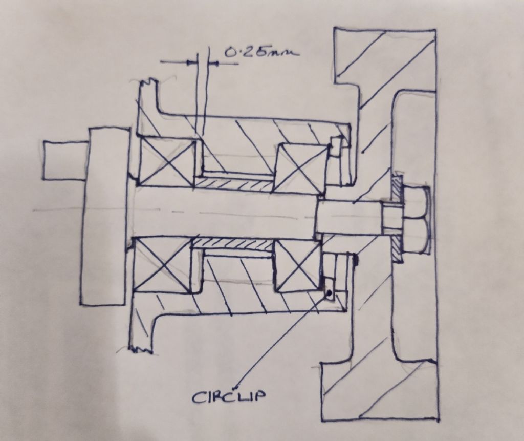
                          I've attached a sketch of how the bearings should be mounted. This is for a rotating shaft, stationary housing. The bearings are clamped to the shaft by the nut on the end of the shaft. the order being nut, washer, flywheel (or prop driver), brg. inner race, spacer, brg. inner race and crankshaft. Note the crank shaft reduces in diameter before the end of the brg. inner race.

                          Hopefully it will be self evident from the sketch that there is clearance for one of the outer races to move axially, the fit in the housing would be a transition fit. The other bearing is the locating bearing. The outer race is against an abutment formed in the housing and held in position with a circlip. I've suggested a circlip but there are other ways.

                          Always best to use the bearing manufacturers recommendations for fits.

                          This arrangement will stop axial loading caused by differential expansion of the various components. Also will greatly reduce the accuracy requirements for the various axial lengths.

                          Look at any well designed assembly (ball bearings/rotating shaft) and this is how it will be done. If the housing rotated then the mounting would be a little different.

                          Over constraint of the bearings, as the are with the Nalon Viper, is a common reason for bearing failure, often mistaken for other problems.

                          The whole business of rolling element bearing mounting is drummed in to students of mechanical engineering, some still get it wrong or choose to ignore these basic principles with the inevitable consequences…..

                          John

                          img_20191218_163339_3.jpg

                          #442258
                          john feeney
                          Participant
                            @johnfeeney58965

                            Hi John MC

                            That`s pretty well how all high performance engines are made although the circlip is often replaced by a threaded locking ring.

                            John Feeney

                            #442261
                            Old School
                            Participant
                              @oldschool

                              It's one way of doing it but not would not be my choice. Just make the crankshaft 10 thou longer and then you can clamp up the rear part of the crank against the centre of the front bearing .The the expansion of the front housing is taken up by the crankshaft moving in rear bearing. The front bearing can be held in with a circlip but I have found it uneccesary, I have clamped the front bearing in one engine I modified but used a clamp ring ring with a left hand thread so if the bearing did rotate it tightened up the ring.

                              The easiest solution is to make the front housing out of steel as is current practice in modern tether car engines press fit bearings C3 or 4 tolerance and the expansion problems almost disappear.

                              #442262
                              Ramon Wilson
                              Participant
                                @ramonwilson3

                                Thanks for your contribution John – your set up is exactly as I described before only reversed. The float of one of the bearings is usually at the front end

                                I have to say that I have never seen this set up as you have drawn in any small single cylinder engine I have been involved with over many years and never ever have I seen a front (or rear) bearing in one held in with a circlip.

                                Whilst I accept it is just a sketch it also implies there is a considerable gap between what appears to be a bearing 'spacer' and the crankcase bore. Again I have never seen any engine fitted with such a spacer only the crankshaft acting as 'one piece' This gap (and there should be one for lubrication) should only be in the order of a thou or so otherwise crankcase compression will be lost. This may be okay for spindles etc but it certainly isn't the norm for small IC engines that I have had experience of.

                                Like all matters there is always several ways to skin a cat but for the type of engines being discussed here this isn't one I would consider as neccessary.

                                The above not intended to be dismissive of your input which is well meant I'm sure but I don't think this is the right advice for anyone attempting to make one of these small engines

                                Regards – Tug

                                #442263
                                Old School
                                Participant
                                  @oldschool

                                  Johm Feeny I cannot say I have seen a modern engine like that who made them would like to have a look. My interest is going fast so anything new is of interest.

                                  #442265
                                  Old School
                                  Participant
                                    @oldschool

                                    Have a read of this it's very interesting approach to the problem of bearings in aluminium crankcases. I have built a 10cc tether car engine designed Mats Bohlin using the front end as described in the article it requires great accuracy to make it work.

                                    Its interesting at the time Mats built this engine Picco was also racing, his engine was conventional design pressed in bearings in aluminium crankcase, Picco set the World record for a 10cc tether car at a fraction under 345kph Mats engine was 0.1kph slower.

                                    http://bmpra.bmfa.org/wp-content/uploads/2016/12/FMV-Engine-history.pdf

                                    #442266
                                    Graham Williams 11
                                    Participant
                                      @grahamwilliams11

                                      On the UK Combat fliers FB page there is a modern combat engine ( think 20-23K rpm), probably Ukraine in origin, shown in all its glory and no spacer or circlip, what I would call ordinary design, should expect the Viper to be an order of magnitude less in the RPM range! If mine runs and starts easily will be well chuffed as I'm not a trained toolmaker/engineer and it is a complicated engine compared with what I've made before.

                                      Cheers

                                      Graham W

                                      #442282
                                      Roy Vaughn
                                      Participant
                                        @royvaughn26060

                                        The definitive source on high performance model engine design is the FMV Story. Although it is 40 years old the principles don't change. They include a detailed description of the main bearing design referencing most of the techniques discussed above.

                                        Roy

                                        http://bmpra.bmfa.org/wp-content/uploads/2016/12/FMV-Engine-history.pdf

                                        #442287
                                        Graham Williams 11
                                        Participant
                                          @grahamwilliams11

                                          Reading all these latest posts, particularly on hi-po engines it comes to mind what sort/class of machinery is being used………. are they outside the normal 'run of the mill' used by the what I believe is the majority of model makers?

                                          #442302
                                          Emgee
                                          Participant
                                            @emgee

                                            Yes of course Jason, must look more carefully at these details.

                                            Emgee

                                            #442304
                                            Old School
                                            Participant
                                              @oldschool

                                              Graham

                                              My interest is racing tether cars the smaller classes1.5, 2.5 and 3.5cc these rev around 40,000 their life is short.

                                              Most of my work is modifying existing engines, making new pistons out of high silicon content aluminium etc.Crankshafts I have made in Hungary and liners chromed and ground in Russia.

                                              My workdhop is fairly standard model engineers one Myford 254 lathe, Seig X3 milling machine and drilling machine bench grinder plus a tool cutter grinder. The latest addition is a Seig KX1 cnc mill.

                                              #442360
                                              Ramon Wilson
                                              Participant
                                                @ramonwilson3
                                                Posted by john feeney on 18/12/2019 17:39:46:

                                                Hi John MC

                                                That`s pretty well how all high performance engines are made although the circlip is often replaced by a threaded locking ring.

                                                John Feeney

                                                Hello John,

                                                I am most interested to see your confirmation of John (MC's) assertion that this is how the make up should be. What area of high performance engine would you be referring too here for though as previously said I have not operated engines at a high end competitive level I would say that I have operated, stripped and rebuilt what would be considered high performance diesel and glow motors over time – SuperTigre, Rossi Ops etc. I have never seen such a set up as described by John in any of these engines so would be very interested to learn more.

                                                Have you set the bearings in your diesel in this fashion as from it's appearance I would guess at a high revving scheurle ported 1.5 with good perforrmance in mind from the outset. You may have missed my previous post but again would like to say you have made a superb job of it and I would certainly like to know more about it.

                                                With regard to Johns drawing the other thing to note is that a flywheel is shown and not a propeller. Obviously a prop would create forward forces that would all be taken on the front bearing as drawn. In a marine situation of course it would be the other way round. How those forces act within a tethered car I have no idea – I assume if a twin shaft engine is used then the forces on each wheel act on the engine laterally pushing on one end and pulling on the other?

                                                I'm afraid I can't quite agree though with Johns assertion that most of these engines bearings are set up incorrectly – yes drawings sometimes do not meet expectation but overal I feel its a bit misleading. That said I'm always willing to learn so all input is always of interest.

                                                Here are my latest engines – 5cc versions of the Mk 3 Oliver Tiger


                                                Hope this will be seen as a post of interest in the subject matter and to further Grahams interest in producing a worthy runner smiley


                                                Regards – Ramon – aka 'Tug'

                                                Edited By JasonB on 19/12/2019 15:48:56

                                                #442382
                                                JasonB
                                                Moderator
                                                  @jasonb

                                                  I suppose things may have moved on a bit with time, a high performance engine from the 50s and 60s like Ramon bases his scratch builds on is probably a bit behind current day thinking.


                                                  Ramon, your images are not showing on the forum

                                                  Edited By JasonB on 19/12/2019 13:26:59

                                                  #442387
                                                  Ramon Wilson
                                                  Participant
                                                    @ramonwilson3

                                                    Hello Jason, yes I guess they are but if commercial engines have moved on it would be interesting to hear about them. My last high performance engine was an OPS 90 marine – I didn't strip it down however but would never imagined it had the set up as described above – maybe it did – anyone know? Do these small 'nitro' engines fitted to R/C cars have such a lower end – I'd certainly like to see their make up if so.

                                                    Can't explain the image situation Jason I pasted the URL in the box and set the image size – it appears on my PC okay.

                                                    The full build and images can of course be seen on MEM here

                                                    Regards and Seasons greetings – Ramon

                                                    #442393
                                                    Emgee
                                                    Participant
                                                      @emgee

                                                      Ramon

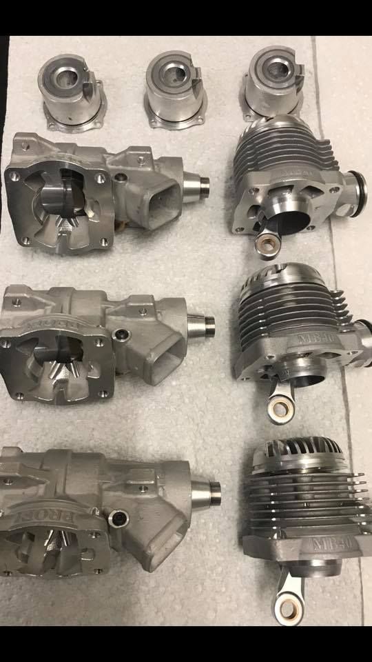
                                                      The current top performing pylon racing engine used in the FAI Class F3D 6.5cc 2 stroke glow ignition powered models is from MBProfi in Holland, the earlier articles describe his engine development for c/l team race engines.

                                                      The crankshaft on these engines is supported at the front by a ceramic ballrace and secured by a locking ring, the bearing is shimmed to achieve the required shaft endfloat.
                                                      The rear is supported by ceramic balls running in a groove ground into the shaft and an outer race, the cage is a phenolic material.

                                                      The builder is currently experimenting with fit of the rear race and has found less problems are encountered if there is good clearance within the bearing arrangement.

                                                      Rob is still making team race engines from solid and competing in most European control line contests, he also flies in F3D class using his own engines.

                                                      Emgee

                                                      Dismantled engines to give some idea of design,

                                                      mb engines dismantled.jpg

                                                      Edited By Emgee on 19/12/2019 14:31:04

                                                      Edited By Emgee on 19/12/2019 14:37:14

                                                    Viewing 25 posts - 51 through 75 (of 144 total)
                                                    • Please log in to reply to this topic. Registering is free and easy using the links on the menu at the top of this page.

                                                    Advert

                                                    Latest Replies

                                                    Home Forums I/C Engines Topics

                                                    Viewing 25 topics - 1 through 25 (of 25 total)
                                                    Viewing 25 topics - 1 through 25 (of 25 total)

                                                    View full reply list.

                                                    Advert

                                                    Newsletter Sign-up