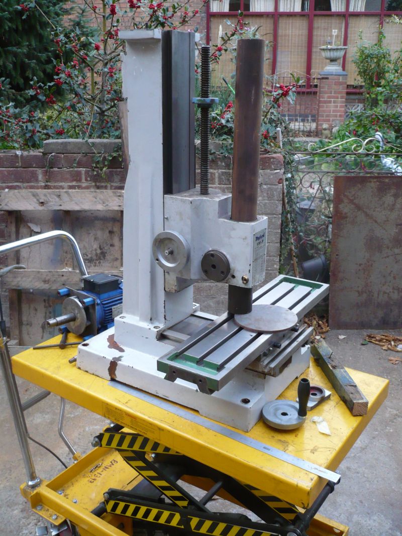
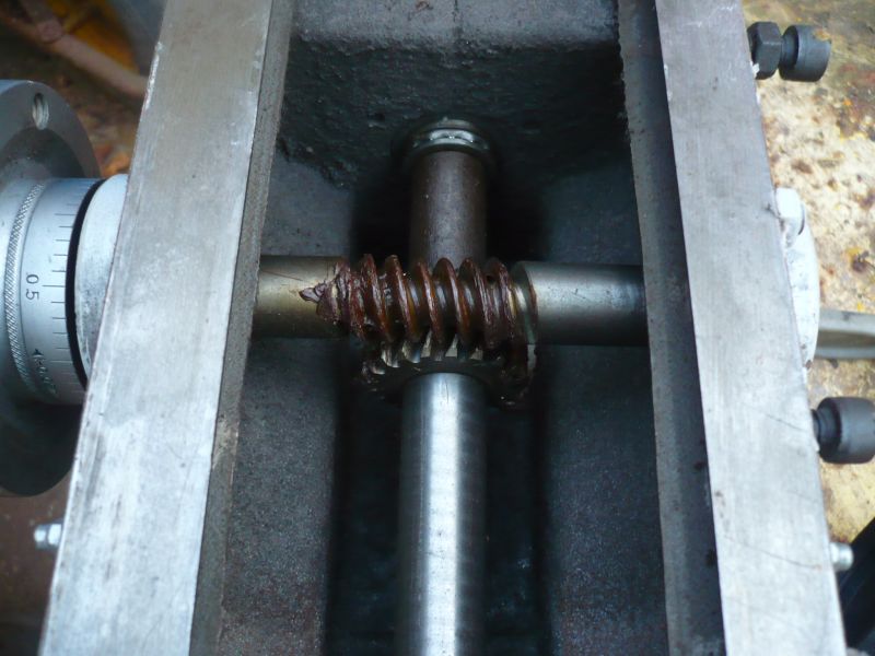
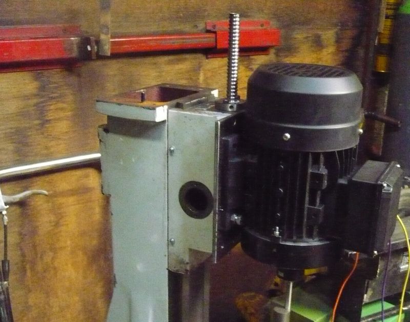
Myford VMB Mill conversion to CNC
Myford VMB Mill conversion to CNC
- This topic has 7 replies, 5 voices, and was last updated 19 January 2015 at 16:07 by
 John Stevenson 1.


- Please log in to reply to this topic. Registering is free and easy using the links on the menu at the top of this page.
Latest Replies
-
- Topic
- Voices
- Last Post
-
-
Robert Atkinson will be proud of me :)
1
2
Started by:
Michael Gilligan
in: Electronics in the Workshop
- 17
-
3 February 2025 at 01:53
Steviegtr
-
question about correcting error introduced by using straight slide in valve gear
Started by:
Chris Kaminski
in: Locomotives
- 4
-
2 February 2025 at 23:39
duncan webster 1
-
Had Another Go
1
2
…
14
15
Started by:
Nigel Graham 2
in: CAD – Technical drawing & design
- 22
-
2 February 2025 at 23:24
Nigel Graham 2
-
What Did You Do Today 2025
1
2
Started by:
JasonB
in: The Tea Room
- 19
-
2 February 2025 at 23:16
Nigel Graham 2
-
ZYTO mini Lathe – need help!
Started by:
theshonkymachinist
in: Beginners questions
- 6
-
2 February 2025 at 22:48
Nigel Graham 2
-
Myford Topslide base casting graduations
Started by:
Martin Kyte
in: Workshop Tools and Tooling
- 2
-
2 February 2025 at 22:26
Baz
-
A New Scam Format?
Started by:
Nigel Graham 2
in: The Tea Room
- 4
-
2 February 2025 at 21:54
Vic
-
The wonders of AI…
1
2
Started by:
Robin Graham
in: The Tea Room
- 14
-
2 February 2025 at 19:21
Michael Gilligan
-
NEW LOOK – Model Engineer & Workshop
1
2
3
4
Started by:
sohara
in: Model Engineer & Workshop
- 36
-
2 February 2025 at 18:33
Graham Titman
-
Classical architectural detail..
Started by:
Diogenes
in: Books
- 2
-
2 February 2025 at 16:31
Michael Gilligan
-
Build Your Own Metal Working Shop From Scrap (7 book series)
Started by:
Dr_GMJN
in: Books
- 5
-
2 February 2025 at 13:54
noel shelley
-
Alibre Workshop/Meshcam pro
Started by:
Ian McVickers
in: CNC machines, Home builds, Conversions, ELS, automation, software, etc tools
- 5
-
2 February 2025 at 13:07
Baz
-
Stuart Beam Engine
Started by:
Phil P
in: Help and Assistance! (Offered or Wanted)
- 2
-
2 February 2025 at 12:55
Phil P
-
Square Bed Lathe
Started by:
Clive Foster
in: Manual machine tools
- 6
-
2 February 2025 at 12:29
bernard towers
-
Using Schneider ATV12 with remote terminal VW3A1006.
Started by:
chrismac
in: Workshop Tools and Tooling
- 5
-
2 February 2025 at 11:48
chrismac
-
Totally unacceptable treatment
Started by:
Me.
in: General Questions
- 13
-
2 February 2025 at 11:33
Vic
-
CAD – Target Enigma
1
2
3
4
Started by:
SillyOldDuffer
in: CAD – Technical drawing & design
- 17
-
2 February 2025 at 10:20
SillyOldDuffer
-
Changes to Well-Known Auction Site
Started by:
Chris Crew
in: The Tea Room
- 19
-
1 February 2025 at 20:10
Mark Rand
-
Vickers Inverted Engine
Started by:
JasonB
in: Stationary engines
- 9
-
1 February 2025 at 18:48
JasonB
-
Colchester bantam cross slide
Started by:
Marcel Jolinon
in: Manual machine tools
- 3
-
1 February 2025 at 18:01
Bazyle
-
Early Myford Super-7B gear change wheels??
Started by:
flatline
in: Beginners questions
- 8
-
1 February 2025 at 17:46
Brian Wood
-
Mobile workshop
Started by:
Sonic Escape
in: The Tea Room
- 12
-
1 February 2025 at 17:05
bernard towers
-
building milling machine made from scrap part 1
Started by:
celso ari schlichting
in: General Questions
- 1
-
1 February 2025 at 16:51
celso ari schlichting
-
My week this week! My workshop videos
1
2
…
11
12
Started by:
Phil Whitley
in: The Tea Room
- 13
-
1 February 2025 at 16:09
Phil Whitley
-
Myford S7 VFD problem
1
2
Started by:
Glyn Davies
in: Manual machine tools
- 21
-
1 February 2025 at 15:13
Nealeb
-
Robert Atkinson will be proud of me :)
1
2
Latest Issues


Newsletter Sign-up
Latest Replies
- Robert Atkinson will be proud of me :)
- question about correcting error introduced by using straight slide in valve gear
- Had Another Go
- What Did You Do Today 2025
- ZYTO mini Lathe – need help!
- Myford Topslide base casting graduations
- A New Scam Format?
- The wonders of AI…
- NEW LOOK – Model Engineer & Workshop
- Classical architectural detail..

