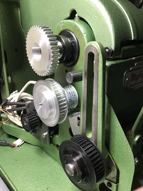
Thanks Matt. From the photo is appears that the spindle gear is larger – normally is as it sits around the spindle which is a large diameter – also has the through hole in it…But perhaps it is larger and the cluster gear at the bottom – the one to which your drive pulley is affixed, is also larger, ie , the same size as the spindle gear. Moot, as you say it is 1:1 all the way through!.
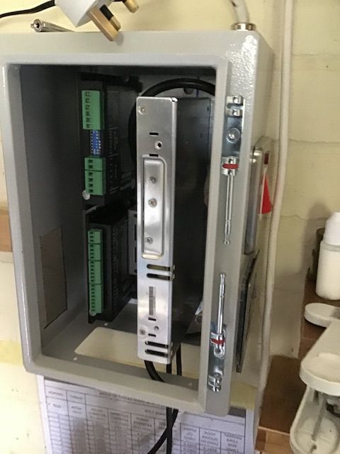
A bit of an update on my Rocketronics journey, stepper fitted, encoder fitted, electronics installed In cabinet, some how I made a balls up, the instructions said to connect encoder using Rj45 connector but some how when fitting the Rj45 plug the live ( red) and ground ( black ) got crossed so have had to order another encoder from Germany, so waiting for that to arrive, a bit annoying but there it is.
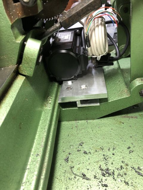
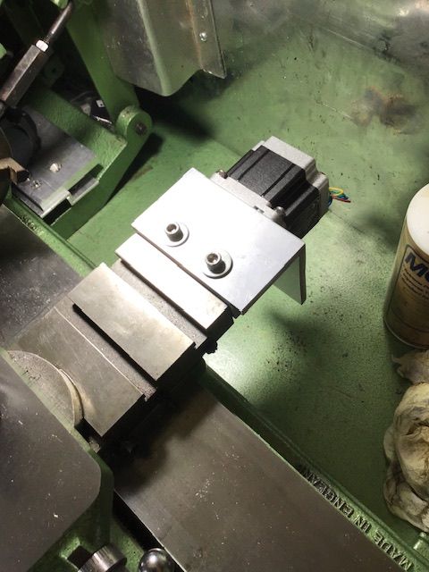
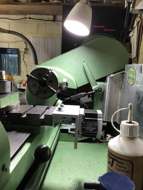
while I await the encoder I am having a think as to fitting the X stepper onto the back of the crosslide, not sure how I am going to do that yet as I don’t want it on the front.
I have since the picture was taken cut the banjo arm to just leave the bit around the leadscrew, and fitted the belts to make sure everything runs true although I have removed the spindle to encoder one.
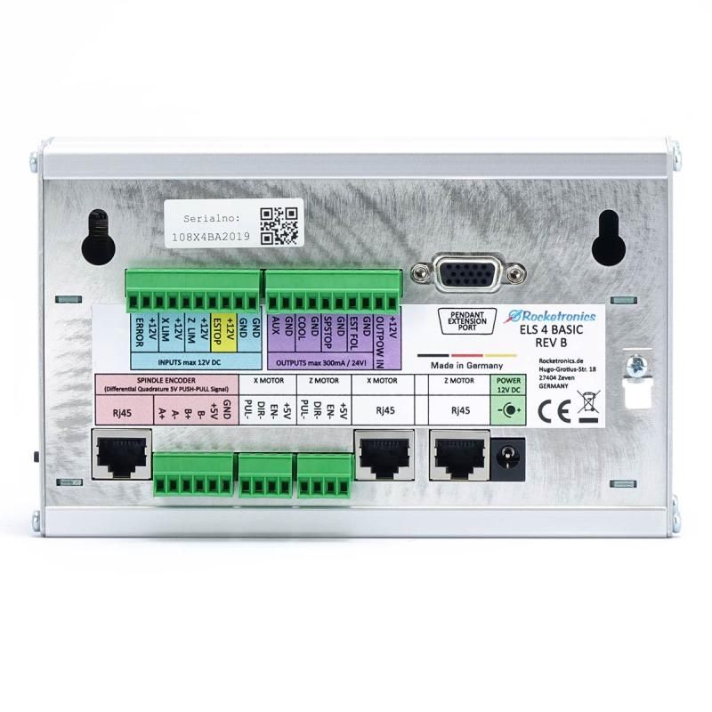
If you connect the encoder to the ELS box using the screw terminals, then you don't need a differential line driver but if you decide to use an RJ45 (shielded ) cable to connect to the encoder to the box then you do. The diff. line driver staggers the signals to reduce any chance if interference. (my description!!)
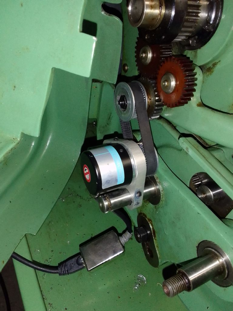
I made us a neat little inline RJ45 connector using Rocketronics line driver so I could easily connect up the encoder. (as per photo below)
I have replied to your message. You need to connect the spindle encoder in the bottom left of the photo – ie section 'spindle encoder'. If using the RJ45 then use a line driver. If not line driver, then the connector.
Thanks for the replies but as the benefit of the Rj45 is the shielded cable according to Rocketronics and as I am using shielded cable anyway I can’t see it would be any different, so have decided to wire direct.
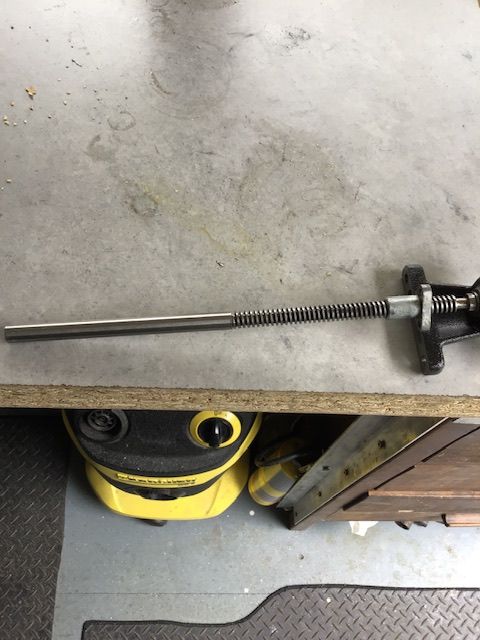
Finally finished fitting the X stepper today, the end of the leadscrew had no thread on the last 12mm but was tapered so I turned it true using a graver then used a length of 10mm silver steel bored a hole to suit the leadscrew and then drilled both for a pin but I also used locktite, so that is all the mechanical work finished now also been doing some of the wiring while I am waiting for the new encoder to arrive
Had to clean the swarf before I started, then I had three clocks come in so I had to make a mess again to make some screws as a few were to damaged to repair, it’s fun making 10 & 12 BA screws on the Myford, it was easier when I had the Pultra but don’t have room for both much to my annoyance.
I have spent the last god knows how many days wiring everything up and although I I have only made sure the steppers are working I am chuffed to bits, I have only tried the fast and slow jog on both the leadscrew and the crosslide they are working albeit the wrong way round but that can be easily changed in the settings along with some other settings IE pitch of lead screws , how much backlash each screw has ( very hand that it takes that into account)
plus a few other settings, I have already put the leadscrew 8 tpi converted to 3.175mm in the settings but I am unable to find the pitch of the crosslide screw , I would have thought it would be in the manual but I can’t find it, so if anyone knows what the pitch of a Myford 10 imperial crosslide screw is it would be much appreciated.
Dell
never mind I have found it 10 tpi converts to 2.540mm.
First cuts with the Rocketronics ELS, Not the best of videos but at least it shows the ELS working , I didn’t have the backlash setting correctly with the first cut but after checking several times in various places it averaged out at 0.003” so the second cut was pretty much spot on