Myford Ml7 Technical Drawings

Advert

Myford Ml7 Technical Drawings

Home Forums Model Engineers’ Workshop. Myford Ml7 Technical Drawings

Viewing 6 posts - 26 through 31 (of 31 total)
  • Author
    Posts
  • #660387
    Howard Lewis
    Participant
      @howardlewis46836

      Purely an aside, Try finding a Tap for 6.354 mm x 1.27 mm, or 0.907 mm pitch!

      Or looking for 0.236 x 25.4 " one!

      I'll settle for 1/4 BSW or UNF, or M6

      If a machine was originbnally made to Imperial (Or Metric ) dimensions, best to stick to those units.

      Yes, Ive come across some hybrids, 3/8 BSF at one end of a stud and 3/8 UNF at the other, or 5/16 BSF bolt with a 5/8 A/F head, but those wouldn't have beeen my choice.

      Yes, we quote BA sizes in Imperial, but really are Metric (O BA is 6 x 1, with succeeding sizes decreasing by a factor 0.9 ) The odd ball feature is the 47.5 degree thread form,, but that might be the Thury parentage to differ from both Whitworth, and Metric form

      Measuring items in units which were not used originally just makes for complications

      Witness film speeds in Russian Gost units rather than Scheiner or ASA

      DON'T mention Weston or Hurter and Driffield, or the A/F sizes for Whitworth form fasteners!

      Howard

      Advert
      #660388
      David-Clark 1
      Participant
        @david-clark1

        Hi Howard, I think converting threads directly is a stupid idea and doubt that was what the original poster meant.

        Yes, metric dimensions would be fine but threads should be suitably selected for the jo.b in hand wether they are imperial, metric or measured in bananas.

        #660405
        HOWARDT
        Participant
          @howardt

          A design is basically imperial or metric, not both. While you can use threads of one in the other, where I use metric fasteners in my imperial engine builds, you shouldn’t convert dimensions unless you merely want to use measuring devices in the other standard. Trying to round dimension or use material sizes will create all sorts of problems with fits and clearances. Metrication or imperialisation needs to be applied creating a complete set of new working drawings with all the fits and clearances worked out to ensure a working model.

          #660408
          JasonB
          Moderator
            @jasonb

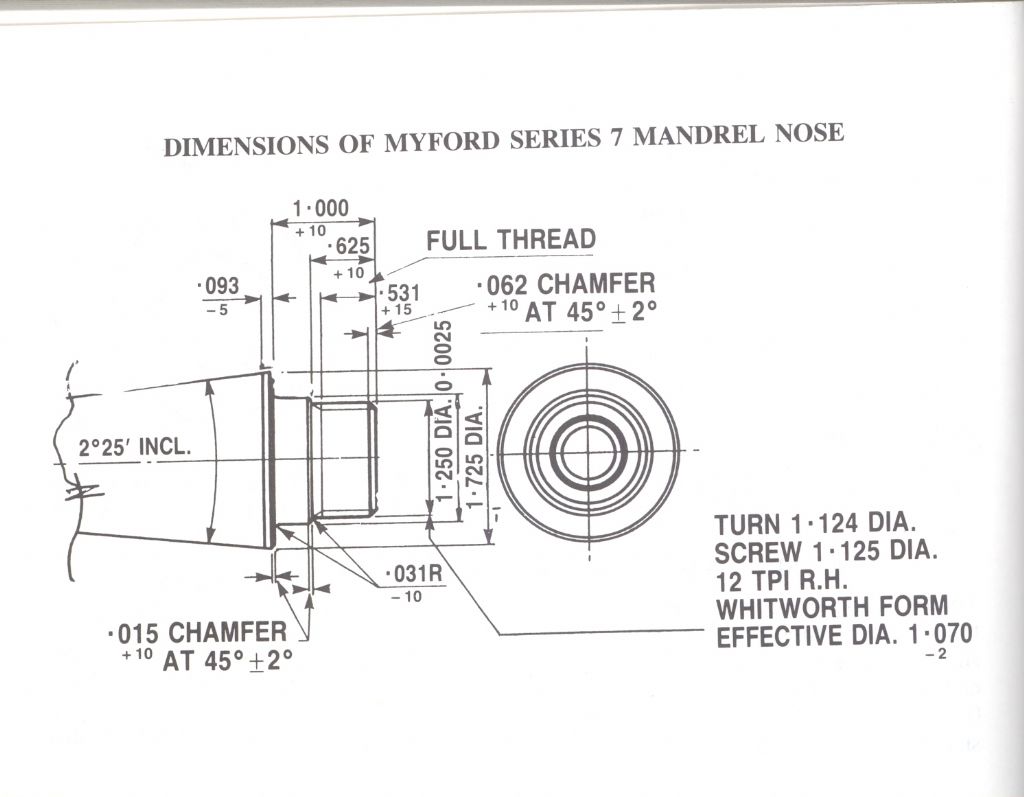
            I think this is an original Myford drawing for the spindle nose, not sure how easily those -ve figures would translate to modern H & h fits. Certainly easer to see how many thou under or over you can be than having to go looking up charts and working out what the tolerences are in microns.

            #660434
            Alan Donovan
            Participant
              @alandonovan54394

              Hello.

              First.

              To follow on from JasonB’s comments on the dimensioning of Myford parts. Myford (Beeston) used a ‘metal off’ system of tolerancing for all their manufactured parts. This was to enable the engineer actually cutting the metal to have a target dimension to achieve, but if he/she went over that dimension they would almost certainly still be within tolerance.
              It also removed the need for the operative to undertake the mental mathematics needed with the plus and minus tolerancing systems, where maths errors can lead to potentially higher scrapage rates for components.

              As we all understand, it is easier to remove excess metal than replace what we removed in error.

              Second.

              If I remember correctly, I think there was reference in this thread to wax(?) printing components to investment cast in metal. Would this require two CAD files? The second file to print an enlarged wax component to allow for casting shrinkage.  Plus the additional metal (wax) for where machining is required.

              All the best to everyone. Alan


              Edited By Alan Donovan on 18/09/2023 07:44:49

              #660435
              JasonB
              Moderator
                @jasonb

                I think most people making their own patterns would print in somnething like PLA which is the usual basic filament material and then after some surface prep use that as the pattern. One or two may CNC cut the pattern.

                You would ideally want a STL file for printing and STP or STEP if CNC cutting with suitable allowance for shrinkage of the chosen metal, machining allowances added to all faces to be machined including draft angle, core prints added as required and then suitable core box drawings/files to form the cores in. If the part needed to be split in half then you would want two files and need to include pins/sockets to locate the two halves together. Then there would be a separate machining drawing required.

              Viewing 6 posts - 26 through 31 (of 31 total)
              • Please log in to reply to this topic. Registering is free and easy using the links on the menu at the top of this page.

              Advert

              Latest Replies

              Viewing 25 topics - 1 through 25 (of 25 total)
              Viewing 25 topics - 1 through 25 (of 25 total)

              View full reply list.

              Advert

              Newsletter Sign-up