Myford ML7 motor wiring

Advert

Myford ML7 motor wiring

Home Forums Beginners questions Myford ML7 motor wiring

Viewing 25 posts - 1 through 25 (of 44 total)
  • Author
    Posts
  • #163164
    Steve Terry
    Participant
      @steveterry41719

      Help please!

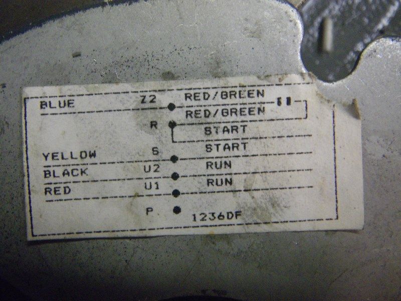
      I have a Myford lathe and it needs a new motor. I have an EMG elettromeccanica one that fits physically (it was supplied as a replacement for the original) My problem is the terminal markings (lathe is fitted with a Dewhurst reversing switch)

      What do I connect to where?

      Motor terminals are:

      U1(blue wire from motor) currently linked to W2 (red wire from motor)

      V1 (red wire from motor) currently linked to U2 (one side of capacitor connected)

      W1 (nothing connected)

      V2 (brown wire from motor and other side of capacitor)

      Drum switch is connected to the eight terminal block as per drum switch instructions.

      Many thanks

      Steve

      Advert
      #7295
      Steve Terry
      Participant
        @steveterry41719
        #163182
        Adam Harris
        Participant
          @adamharris13683

          Is the Dewhurst set up for 3 phase or single phase ? Adam

          #163183
          Steve Terry
          Participant
            @steveterry41719

            Sorry, I should have said single phase.

            #163187
            Les Jones 1
            Participant
              @lesjones1

              Hi Steve,
              Is the information you have given referring to the old motor and wire colours the wires that come from the switch, (Or are they the wires from inside the motor to the terminals.) ?

              Les.

              #163190
              Steve Terry
              Participant
                @steveterry41719

                Hi Les,

                The info refers to the new motor (unfortunately the old one was removed before I got it) and the wires are those that disappear into the depths of the motor.

                At present there is no wiring between the terminal block and the motor.

                Thanks Steve

                #163191
                Adam Harris
                Participant
                  @adamharris13683

                  Sorry, rereading your post I can see that you have a single phase setup. Well U1 and U2 are normally Run terminals but you need to establish if this is the usual capacitor start, induction run motor or capacitor start capacitor run motor, Assuming it is the former, one circuit is the U1-U2 run circuit and the other circuit is the Capacitor, start, centrifugal switch circuit. The Dewhurst taps into the U1 and U2 circuit , taking the flow into the Capacitor, start, centrifugal switch and reversing the direction around the cap,start,centrifugal sw circuit according to whether switched to Fwd or Rev. Bearing this i mind, you should be able to work out what goes where without relying on the existing colour coding which may be erroneous. Tubal Cain covers most motors wiring in his book although I do not have it to hand. Does the new EMG have resilient rubber mounts – shame if it does not.

                  #163195
                  Steve Terry
                  Participant
                    @steveterry41719

                    Hi Adam,

                    Does that mean I have to remove the physical links between U1-W2 and V1-U2?

                    Does it also mean that I only have a connection between two cores (to U1 and U2- three counting earth) from the motor to the Dewhurst?

                    No resilient mounts unfortunately!

                    apologies if these questions seem obvious.

                    Steve

                    #163207
                    Les Jones 1
                    Participant
                      @lesjones1

                      Hi Steve,
                      You will need a four core (+earth) cable between the motor and the switch. You will need to remove both links. I am making no assumptions on the colour coding of the wires inside the motor. I believe that the run winding is between V1 and W2 and the start winding between U1 and V2. Confirm this is the case by measuring the resistance between V1 and W2 I would expect it to be a few ohms (Probably less than 10) Measure the resistance between U1 and V2 I would expect this to be between 10 and 20 ohms. Confirm that you get an infinite reading between V1 and V2 IF THIS IS THE CASE then the pair from the switch that does not reverse polarity goes to V1 and W2 The pair that reverse polarity between forward and reverse go to U1 and U2. If you cannot identify the two pairs from the switch we will need to ask more questions to identify them.

                      Les.

                      #163214
                      Adam Harris
                      Participant
                        @adamharris13683

                        Sorry Steve, but since your U2 is connected to the capacitor circuit it would seem that the U1-U2 circuit is not the Run circuit as I thought. You will have to research italian wiring diagrams online. Without trying to irritate you, I would suggest selling it on ebay and buying a used resilient mount British motor (Brook Crompton or Hoover) for it on ebay which will give less vibration and easier for spares if ever needed.

                        #163234
                        Neil Wyatt
                        Moderator
                          @neilwyatt

                          Rather than remortgaging for a Brook Crompton, he Manufacturer's website has this pdf which shows the connections with English instructions:

                          http://www.emgelettromeccanica.it/data/public/file/9_schemi_collegamento.pdf

                          Neil

                          Edited By Neil Wyatt on 10/09/2014 08:44:29

                          #163238
                          Les Jones 1
                          Participant
                            @lesjones1

                            Well spotted Neil, (I looked on their website but could not find that information.) I seems to confirm my theory as to how the motor is wired. There seems to be an error on the connections for anticlockwise rotation. The right hand end of the capacitor is not connected to anything. It should go to V2 (One end of the start winding ) as in the drawing for clockwise rotation.

                            Les.

                            #164319
                            Ian Symes
                            Participant
                              @iansymes12360

                              Hi Guys

                              I have a similar problem.

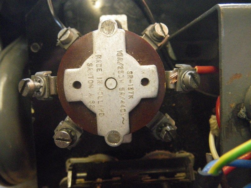
                              I can't get the Stanton switch to switch forward/reverse from the Brooke Crompton motor.

                              On my Super 7

                              The switch has different connections to that shown in the manual.

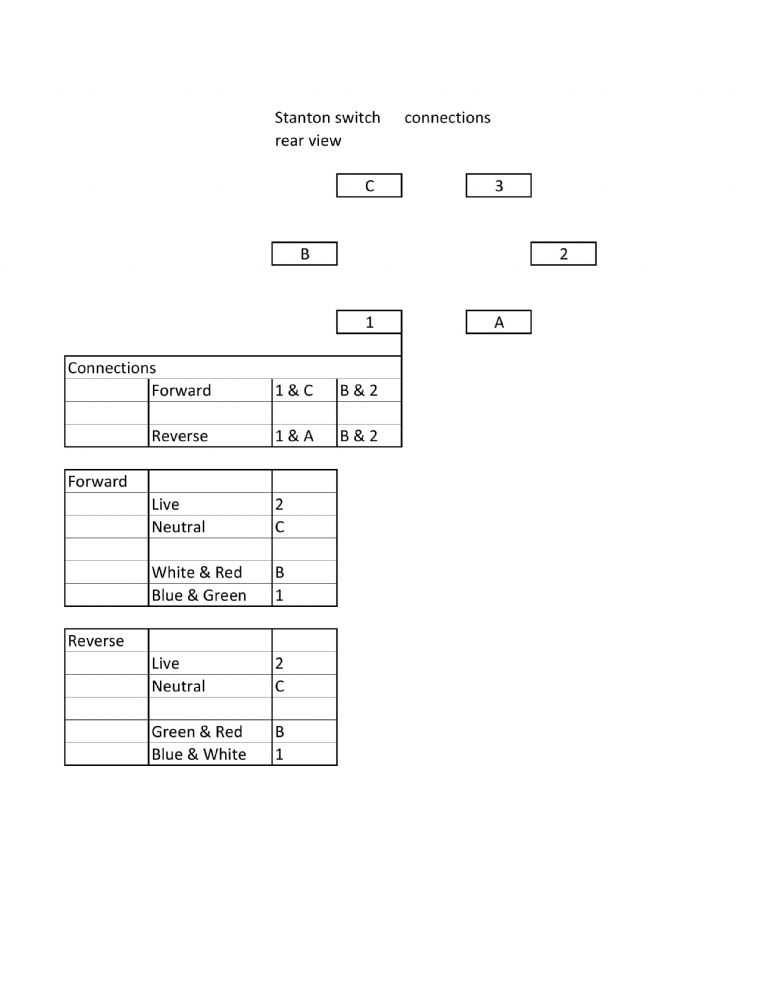
                              LH from the top, rear view

                              C B 1

                              RH

                              3 2 A

                              I have drawings on PDF but can't attach them.

                              Without them the above wont mean a lot.

                              How do I attach them?

                              Thanks

                              Ian

                              #164342
                              Les Jones 1
                              Participant
                                @lesjones1

                                Hi Ian,
                                As far as I know this forum does not support .PFD files to be inserted into forum posts. You could convert it to a .JPG file by using a screen capture program such as "Gadwin print screen" You could also look for a utility program to do the conversion. You could also use "Dropbox" by putting the .PDF file in your public folder. Then put the URL of the public link to the file as a link in your forum post. If you only need to send it to one person then get them to send you a PM with their email address (To avoid putting email addresses on the forum.) then send it as an attachment to a normal email.

                                Les.

                                #164352
                                Ian Symes
                                Participant
                                  @iansymes12360

                                  Hi Les,

                                  Thanks for the info.

                                  I have converted them to .JPG but still can't load them.

                                  I will try Dropbox when I get home tonight.

                                  Ian

                                  #164363
                                  Les Jones 1
                                  Participant
                                    @lesjones1

                                    Hi Ian,
                                    To add pictures to a post the files have to be first uploaded to your albums. To do this click on albums on the green band near the top of the forum web page. When you have the files there you can add them to a post by clicking on the camera icon at the top of the box where you are typing the message. By the way Thanks for bringing this thread back to life since the OP seems to have lost interest in having his problem fixed.

                                    Les.

                                    Edited By Les Jones 1 on 23/09/2014 11:46:01

                                    #164371
                                    Ian Symes
                                    Participant
                                      @iansymes12360

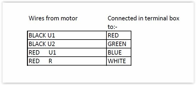
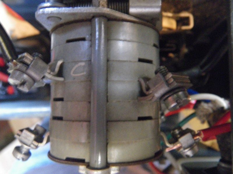
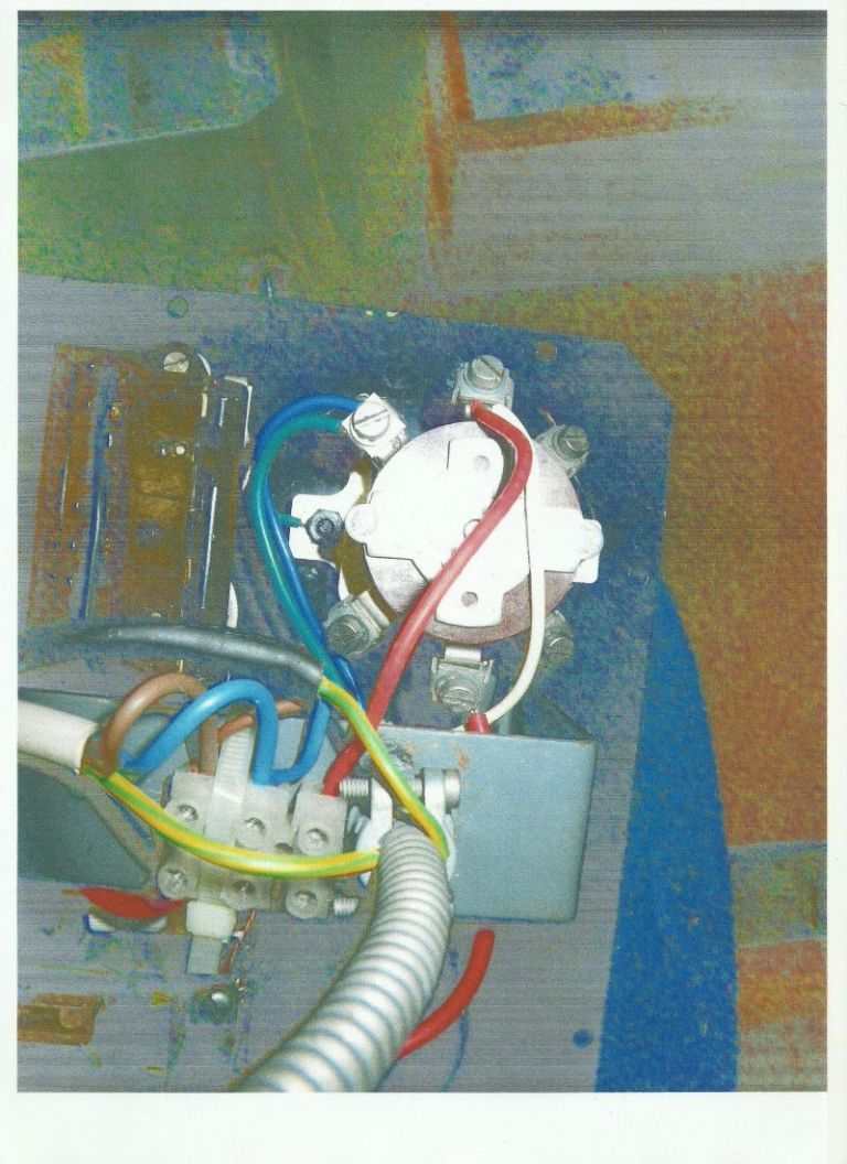
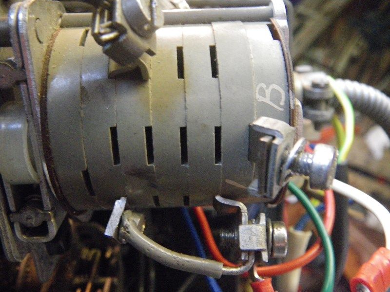
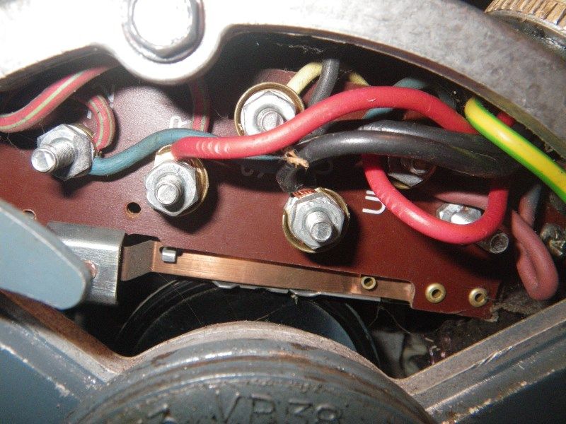
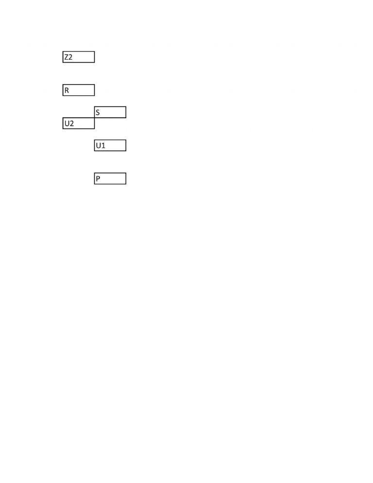
                                      terminal box.jpgterminal box connections.jpgswitch top.jpgswitch photo.jpgswitch link.jpgswitch end.jpgswitch connections.jpgmotor wiring.jpgmotor layout.jpgmotor end plate.jpg

                                      #164372
                                      Ian Symes
                                      Participant
                                        @iansymes12360

                                        Hi Les.

                                        As you can see the photos are on the forum,

                                        thanks to a friend who came into the office.

                                        Ian.

                                        #164381
                                        Les Jones 1
                                        Participant
                                          @lesjones1

                                          Hi Ian,
                                          Can you confirm if the switch is 2 positions (Forward Reverse) or 3 positions (Forward off reverse) ? Also can you confirm that the table labelled "connections" in the picture of switch information shows the contacts that connect together in the 2 or 3 positions of the switch and in no position terminal 3 connects to any of the other terminals ? If this is the case then this switch cannot reverse the motor. Is this data from a document or have you worked it out by testing for continuity between the terminals ?

                                          Les.

                                          #164386
                                          Ian Symes
                                          Participant
                                            @iansymes12360

                                            Hi Les,

                                            The switch is 3 position.

                                            It is probably the original switch the lathe is on a Myford industrial stand.

                                            The switch position is something I worked out.

                                            I'll check position 3 tonight.

                                            Ian

                                            #164462
                                            Ian Symes
                                            Participant
                                              @iansymes12360

                                              Hi Les,

                                              Thanks for all your help.

                                              3 is connected to C when the switch is in reverse.

                                              Ian.

                                              #164463
                                              Les Jones 1
                                              Participant
                                                @lesjones1

                                                Hi Ian,
                                                I would expect 3 to show continuity to A in the forward position of the switch. Can you double check if this is the case. If it is not the case then I suspect that the switch is faulty. If it is the case it should be possible to get the switch to work but it will only provide single pole isolation of the run winding. (If it was used for reversing a 3 phase motor then it would isolate all 3 phases in the centre off position.)  In one of the pictures of the switch there is a short grey wire linking two terminals. The right hand terminal is 1 (I think) Which terminal is the other end connected to ? In the picture they both seem to be in the same angular position which does not make sense as the 6 terminals appear to be at 45 deg, 90 deg, 135 deg, 225 deg, 270 deg, and 315 deg.

                                                Les.

                                                Edited By Les Jones 1 on 23/09/2014 22:29:19

                                                #164477
                                                Ian Symes
                                                Participant
                                                  @iansymes12360

                                                  Hi Les.

                                                  I will check the switch position tonight.

                                                  The link in the photo is below, in line with terminal 1 looking from the back of the switch and is not marked.

                                                  Ian.

                                                  #164478
                                                  Les Jones 1
                                                  Participant
                                                    @lesjones1

                                                    Hi Ian,
                                                    So there are 7 terminals on the switch. (Or are there even more ?)

                                                    Les.

                                                    #164499
                                                    Ian Symes
                                                    Participant
                                                      @iansymes12360

                                                      Hi Les.

                                                      No more just the 7

                                                      Ian.

                                                    Viewing 25 posts - 1 through 25 (of 44 total)
                                                    • Please log in to reply to this topic. Registering is free and easy using the links on the menu at the top of this page.

                                                    Advert

                                                    Latest Replies

                                                    Home Forums Beginners questions Topics

                                                    Viewing 25 topics - 1 through 25 (of 25 total)
                                                    Viewing 25 topics - 1 through 25 (of 25 total)

                                                    View full reply list.

                                                    Advert

                                                    Newsletter Sign-up