Myford ML7 cross slide screw repair

Advert

Myford ML7 cross slide screw repair

Home Forums Manual machine tools Myford ML7 cross slide screw repair

Viewing 15 posts - 1 through 15 (of 15 total)
  • Author
    Posts
  • #608368
    Jon Halland
    Participant
      @jonhalland84811

      Hi All,

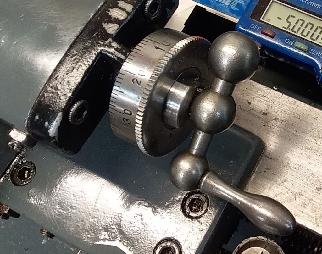
      My "new" 1950 Myford ML7 came with a home made larger scale for the cross slide, see pic.

      The engineering is not great and was quite destructive to the handle thread. I do have the original scale and would like to use it. I'm not sure if this is possible with the state of the handle thread. I've cleaned up lots of bolts with files and using dies from the screw end, but this looks pretty damaged here, so very difficult to get a correct start. I guess the best way would be to use some sort of clamping die and unscrew/cut the thread. The thread is 1/4'' BSF.

      Is such a die available?

      Is the thread so bad that it's not likely to succeed?

      Thanks.

      pxl_20220804_060317834.jpg

      pxl_20220804_060328658.jpg

      pxl_20220804_060350477.jpg

      Advert
      #14629
      Jon Halland
      Participant
        @jonhalland84811
        #608370
        Hopper
        Participant
          @hopper

          YOu can get a 1/4" BSF die from Tracy Tools and many other ME suppliers who advertise on here and in the mag. It will clean that thread up ok. But your screw end looks pretty nasty and will be missing a lot of thread right where the original ball handle screws on, a critical point. (That damage would have been done by the original set-up, not the larger dial.)

          I would highly recommend sticking with your larger resettable dial, maybe using a tiny copper pad under the end of the grub screw so it does not chew up the thread again after you clean it up. The missing bits of thread will not be so critical in that set up.

          Plus the original ML7 dial is a miserable little thing that should have been tossed away at the factory. Too small to read, does not reset to zero, and so cheaply made the lines are not precision at all and the Mazak internal thread strips every time a stiff breeze blows in the workshop door. That is why someone went to the bother of making their own larger, resettable replacement. Well worth having. I made my own larger resettable dials for the ML7 and regard it as the best mod ever made. Should have done it years ago. Being able to reset the dial to zero massively simplifies life when taking multiple cuts or screwcutting etc. No more mental gymnastics and felt pen marks and cursing and swearing.

          If worst comes to worst, you could cut that threaded spigot off, drill and tap the end of the feed screw and put in a replacement threaded section. But I would not go that far if the larger dial works ok with a bit of fettling on the uncut screw.


          Edited By Hopper on 04/08/2022 08:43:41

          #608371
          V8Eng
          Participant
            @v8eng

            New replacements are available from Myford.

            #608373
            Hopper
            Participant
              @hopper
              Posted by V8Eng on 04/08/2022 08:40:49:

              New replacements are available from Myford.

              Indeed. As are larger resettable dials that screw directly onto the original screw. It is only a matter of money. Also MEW at some point in the future will be publishing an article I submitted on how to make your own such dials.

              Edited By Hopper on 04/08/2022 08:48:28

              #608375
              V8Eng
              Participant
                @v8eng
                Posted by Hopper on 04/08/2022 08:47:04:

                Posted by V8Eng on 04/08/2022 08:40:49:

                New replacements are available from Myford.

                Indeed. As are larger resettable dials that screw directly onto the original screw. It is only a matter of money. Also MEW at some point in the future will be publishing an article I submitted on how to make your own such dials.

                Edited By Hopper on 04/08/2022 08:48:28

                Yes not cheapo stuff.

                Your article might get me making a resetable dial (if I ever get back into the shop).

                Edited By V8Eng on 04/08/2022 09:09:35

                #608378
                Martin Kyte
                Participant
                  @martinkyte99762

                  I think I would be inclined to turn the thread off and loctite a sleeve onto the new parallel portion of the shaft. You can then set to run true and turn to size and screwcut the thread finishing off with a die. If you are clamping a threaded collar to a threaded section using set screw(s) then the screws should always be fitted with copper or brass pads under the screws so the pads bear on the thread. Copper is soft enough to deform and not ruin the thread but a better way is this.

                  Turn up a small pad of copper/brass to just clear the set screw threaded hole. Thread the collar onto a rod which is close fit on the bore of the collar. Insert the pad into the threaded hole and with a punch down the hole give it a sharp rap with a hammer. This will expand the pad and retain it in the threaded hole. Withdraw the rod through the middle and replace with the correct size tap and fit the set screw. By judiciously advancing the pad with the set screw and turning the tap back and forth a matching thread will be cut in the end of the pad. Reassemble the whole and then when the set screw is tightened there will be absolutely no damage to the thread ever again.

                  Don't thank me, this is the way George Thomas did it. (the pad not the loctite bit)

                  regards Martin

                  Edited By Martin Kyte on 04/08/2022 09:35:10

                  #608390
                  Hopper
                  Participant
                    @hopper
                    Posted by V8Eng on 04/08/2022 09:09:22:

                    Posted by Hopper on 04/08/2022 08:47:04:

                    Posted by V8Eng on 04/08/2022 08:40:49:

                    New replacements are available from Myford.

                    Indeed. As are larger resettable dials that screw directly onto the original screw. It is only a matter of money. Also MEW at some point in the future will be publishing an article I submitted on how to make your own such dials.

                    Edited By Hopper on 04/08/2022 08:48:28

                    Yes not cheapo stuff.

                    Your article might get me making a resetable dial (if I ever get back into the shop).

                    Edited By V8Eng on 04/08/2022 09:09:35

                    It is much simpler than the one in the OP above. More along lines similar to the ones Myford sells today. And all the indexing/graduating and number stamping was done in the lathe by a very simple method. (Me being a totally lazy so and so.)

                    dial.jpg

                    Edited By Hopper on 04/08/2022 10:55:50

                    #608391
                    Hopper
                    Participant
                      @hopper
                      Posted by Martin Kyte on 04/08/2022 09:34:07:

                      Turn up a small pad of copper/brass to just clear the set screw threaded hole. Thread the collar onto a rod which is close fit on the bore of the collar. Insert the pad into the threaded hole and with a punch down the hole give it a sharp rap with a hammer. This will expand the pad and retain it in the threaded hole. Withdraw the rod through the middle and replace with the correct size tap and fit the set screw. By judiciously advancing the pad with the set screw and turning the tap back and forth a matching thread will be cut in the end of the pad. Reassemble the whole and then when the set screw is tightened there will be absolutely no damage to the thread ever again.

                      Don't thank me, this is the way George Thomas did it. (the pad not the loctite bit)

                      Old GHT was a marvel, wasn't he? Just totally in awe of the man.

                      Edited By Hopper on 04/08/2022 10:58:55

                      #608394
                      Jon Halland
                      Participant
                        @jonhalland84811

                        Thanks for the all replies.

                        My primary concern is to get the lathe cleaned up and back running, think exploded view – just a lot less organized. Hence back to original dial fitting which is simple, in it's time very cost effective and not bad design engineering imo. It solves:

                        Adding a dial and fixing it.

                        Adding a handle and fixing it.

                        Locking the cross feed screw in place and setting its tightness using the dial and locking it all with the handle.

                        All this for just 3 components (washer, dial, handle). The drawbacks in this solution are: a handle on a thread (can unscrew) that relies on the soft metal of the dial to 'bite' and fix the whole thing, so limited lifespan.

                        I would like to have an adjustable dial working but the current version is not my kind of engineering:

                        The back plate with the marker is loose and the small holes to hold it are elongated so it can move about a mark. This is part due to poor drilling and it being part of the tightening of the whole screw/dial/handle system.

                        The stud with the 2 set screws is threaded and the set screws forced into the cross feed screw, so to screw the handle on as the last bit the feed screw has to be grabbed with a pair of plies on the other side of the bracket and tightened a lot, not to unscrew in use – all force through the set screws. This is probably what caused most of the damage to the thread.

                        A future project could be to use the marker and dial plates and make a better solution.

                        #608432
                        Hopper
                        Participant
                          @hopper
                          Posted by Jon Halland on 04/08/2022 11:59:03:

                          A future project could be to use the marker and dial plates and make a better solution.

                          When I made mine I thought about using some kind of extension on the existing screw like your previous owner has done and then making some GH Thomas style dials as he designed for the Super 7 but it all got too complicated and full of compromises so went with the simple but effective version in my pic above. It does have the advantage of threaded steel rather than Mazak to lock the handle against, which is a definite plus as you say.

                          #608435
                          Howard Lewis
                          Participant
                            @howardlewis46836

                            The Dial can be resettable, as It looks as if Hopper has done, by having a close fit on the spindle but clamped by a grubscrew with a brass or copper pad under it, to protect the spindle.

                            All that is needed to reset is to ease the grubscrew, reposition the dial and to retighten the grubscrew..

                            What may be more difficult is putting the marks onto the dial, since you will need 100.

                            One way, if you can't find a 100t gear to use as an index, might be to clamp the existing nasty Mazak dial to the blank of the new resettable one, one a mandrel in the chuck, and use that to scribe the lines using a knife tool in the tool post.

                            You can move the Top Slide to and fro, to produce lines of different lengths for the 10s, 5s and units.

                            Howard

                            #608436
                            Howard Lewis
                            Participant
                              @howardlewis46836

                              The Dial can be resettable, as It looks as if Hopper has done, by having a close fit on the spindle but clamped by a grubscrew with a brass or copper pad under it, to protect the spindle.

                              All that is needed to reset is to ease the grubscrew, reposition the dial and to retighten the grubscrew..

                              What may be more difficult is putting the marks onto the dial, since you will need 100.

                              One way, if you can't find a 100T gear to use as an index, might be to clamp the existing nasty Mazak dial to the blank of the new resettable one, one a mandrel in the chuck, and use that to scribe the lines using a knife tool in the tool post.

                              You can move the Top Slide to and fro, to produce lines of different lengths for the 10s, 5s and units.

                              Howard

                              #608439
                              Hopper
                              Participant
                                @hopper
                                Posted by Howard Lewis on 05/08/2022 07:30:59:

                                The Dial can be resettable, as It looks as if Hopper has done, by having a close fit on the spindle but clamped by a grubscrew with a brass or copper pad under it, to protect the spindle.

                                All that is needed to reset is to ease the grubscrew, reposition the dial and to retighten the grubscrew..

                                What may be more difficult is putting the marks onto the dial, since you will need 100.

                                One way, if you can't find a 100T gear to use as an index, might be to clamp the existing nasty Mazak dial to the blank of the new resettable one, one a mandrel in the chuck, and use that to scribe the lines using a knife tool in the tool post.

                                You can move the Top Slide to and fro, to produce lines of different lengths for the 10s, 5s and units.

                                Howard

                                All that will be revealed in the upcoming article in MEW. But no, no grub screw in my design. Screws straight on like the original with no grub screw.

                                The 100 divisions were done using compound gearing with the standard Myford change gears and a special quick-action detent, plus a carriage stop. Very simple all round. (The lazy man's way of doing things!)

                                #608442
                                Howard Lewis
                                Participant
                                  @howardlewis46836

                                  Apologies, Hopper.

                                  Thought that i saw a grubscrew in a flat on the front of the dial.

                                  Having had spring loaded resettable dials slip when turning the handle too fast, I took the easy way out and used the grubscrew method.

                                  A bit clumsy, but doesn't slip so easily!

                                  I await your article with anticipation!

                                  Howard

                                Viewing 15 posts - 1 through 15 (of 15 total)
                                • Please log in to reply to this topic. Registering is free and easy using the links on the menu at the top of this page.

                                Advert

                                Latest Replies

                                Home Forums Manual machine tools Topics

                                Viewing 25 topics - 1 through 25 (of 25 total)
                                Viewing 25 topics - 1 through 25 (of 25 total)

                                View full reply list.

                                Advert

                                Newsletter Sign-up