DMR, I have a Myford S7 of similar age to yours. I have always lubricated the spindle using “the few drops at the start and then close off” system like yourself as I never realised that anything else was intended. I also have the original clutch but strangely have never had any bother with it (and it has been dismantled and reassembled for reasons not associated with the clutch); don’t know why I’ve been lucky.
Mine is a plain 7 not Super 7, and I fitted a second-hand, early-type gearbox. You may already have found this tip:
If yours matches mine, lifting the gear-lever and letting it rest on the casting between the selector slots (obviously with the tumbler-reverse in neutral) gives an unofficial neutral allowing the leadscrew to be rotated freely with the handwheel.
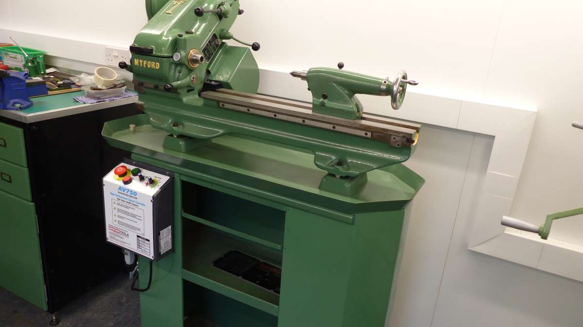
I gave mine a Newton-Tesla 3-ph conversion and am pleased I did. I do of course use the mechanical transmission to advantage as well, particularly as the motor should not be run at very low speeds as a matter of course. OK for reversing a tap or die from the work, but that’s about all.
Note that NT supply a set designed for these lathes.
.
Do though protect the motor of any type, 1ph or 3ph from swarf. Obviously you must not seal ventilation holes and fan grilles, and I fabricated a complete splash-back / motor-guard unit from 3mm grey PVC sheet. It’s held partly by a clamp on the countershaft frame and partly by screws to a batten on the wall behind the lathe.
How do I know?
The hard way…. when machining some bronze.
A long spiral of swarf obligingly descending between the cabinet and me, was the decoy so I did not notice it had a companion sneaking round the back. It found its way into the 3-phase motor like an earthworm on freshly-dug soil. Flash! Crack! All Stop – Finish With Engines. Even in the house, shown by the oven clock off.
I had to send both the motor and control unit back for test and repair. The motor had survived but not the electronics.
Thanks for the replies,I will go through the points raised:-
John Fletcher: Were You looking at the photos of the old motor? I have fitted a new motor and inverter during the rebuild, more photos to come yet.
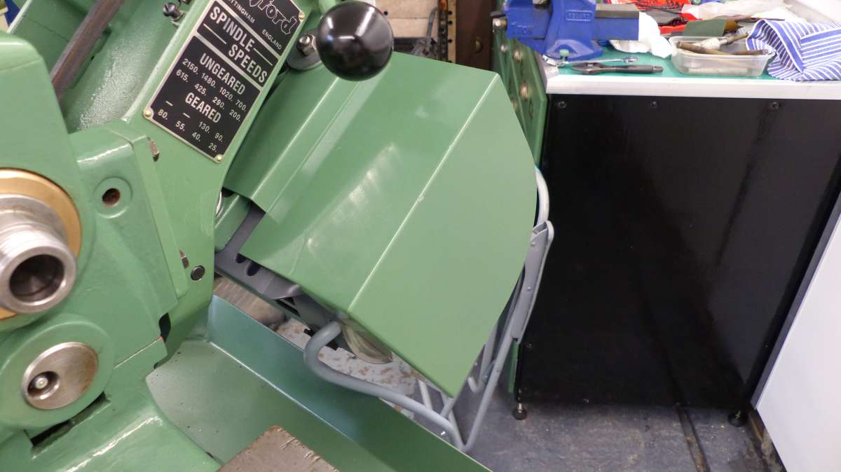
Robert:-Future photos will show that I have fitted a Myford swarf guard to the motor, read somewhere about potential pyrotechnics!
Dennis: Sorry I have been absent, had to pause work on the lathe to sort out the workshop when builder was available, and pick the rebuild up after.
I would appreciate the screw cutting chart for the early gearbox if You can supply it,I would be very grateful.
The alignment of the headstock was checked in both vertical and horizontal planes before tightening the headstock bolts,using a Dial test indicator in the surface guage, pins down against the back shear of the bed and all lined up,using the test bar. Tailstock components were matching numbers and when the above test was repeated with the tailstock centre entered in the test bar there was negligable variation from the first test.
Clutch:- Noticed some slip during testing, I will have to adjust it up tighter,but to be honest with You,with the new motor set up i will probably not be using it much.
Lube system, aleady made a little puddle leaving it open overnight, so found out the messy way how best way To use it! Thanks to Chris H as well!
I’m not worried about geting it mucky, thats what it is there for!
Nigel Graham 2:-
Sorry to hear about You’re swarf woes…Ouch!
As mention above, I have fitted a swarf guard to help counter this.
Thank You for the tip about ‘neutralising’ the gearbox, that will come in handy!
Again, many thanks for looking in and You help and advice.
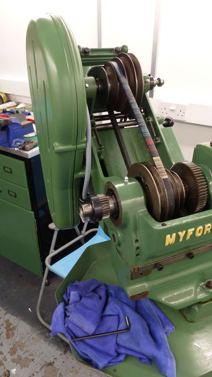
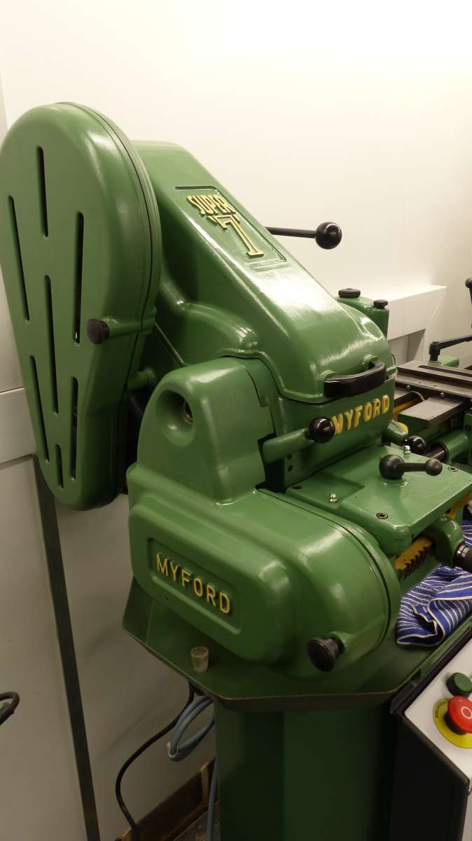
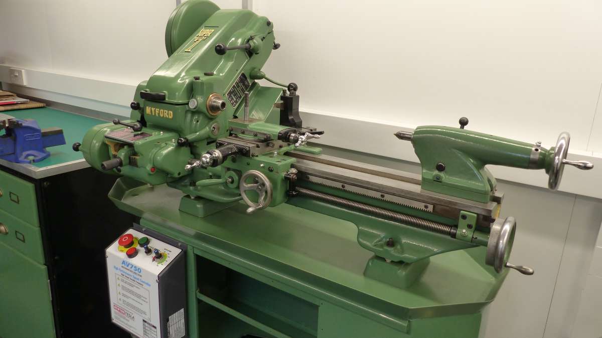
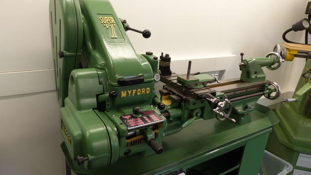
Motor guard fitted, and belts and their guards fitted,original fixing knobs fitted in leiu of spring catches on later models. bump stops made from a length of ‘O’ ring material instead of £4 each (!) from Myfords.
Tumbler reverse and back gear knobs fitted with later plunger fittings to speed up use.
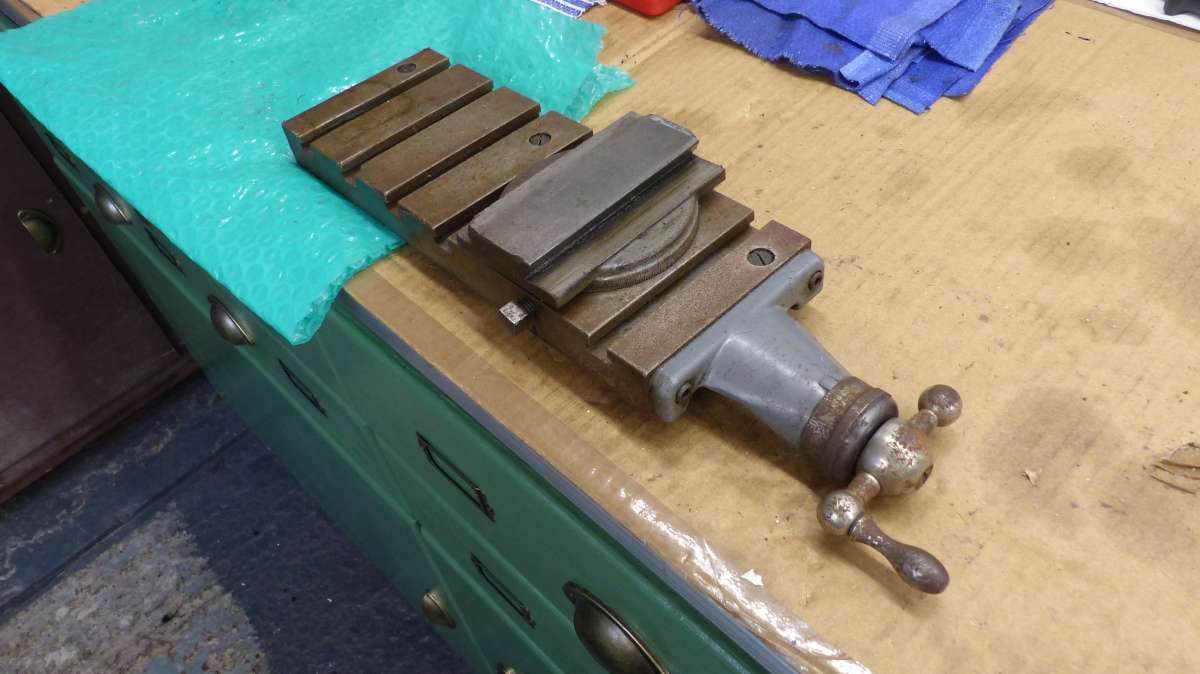
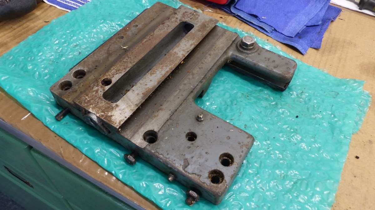
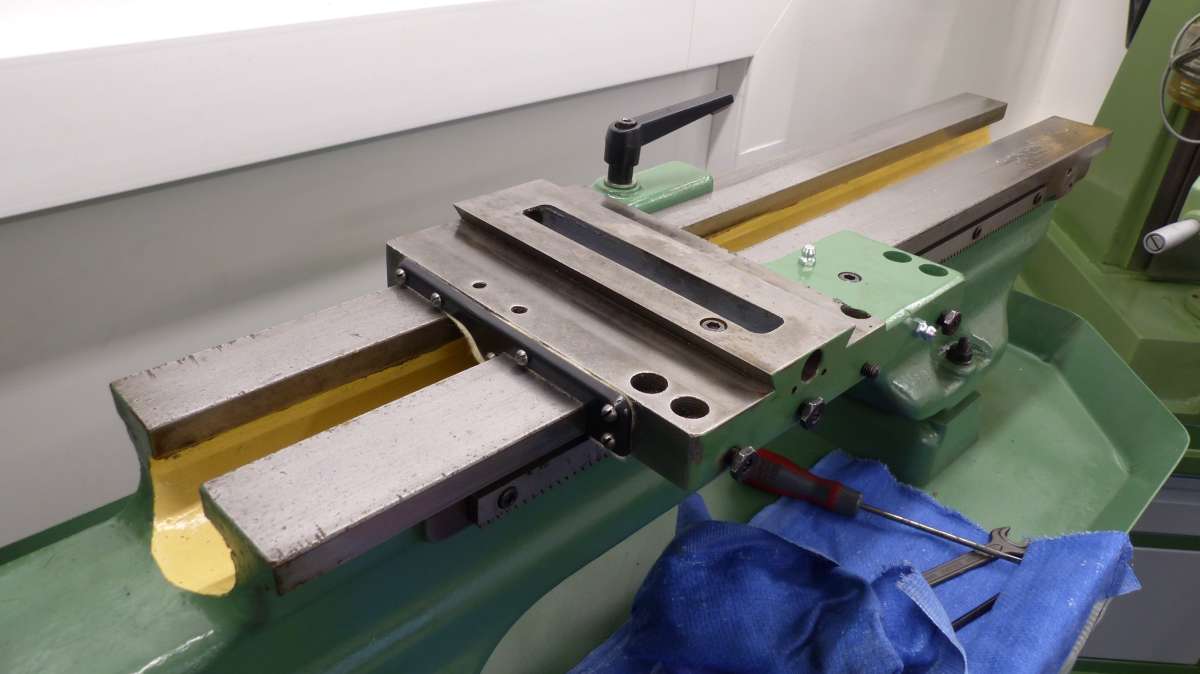
Cross slide and saddle before cleaning up.
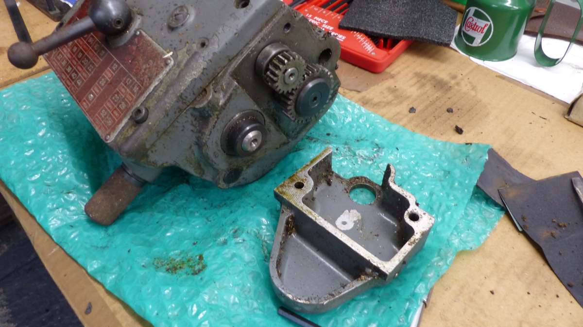
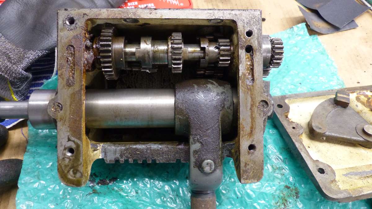
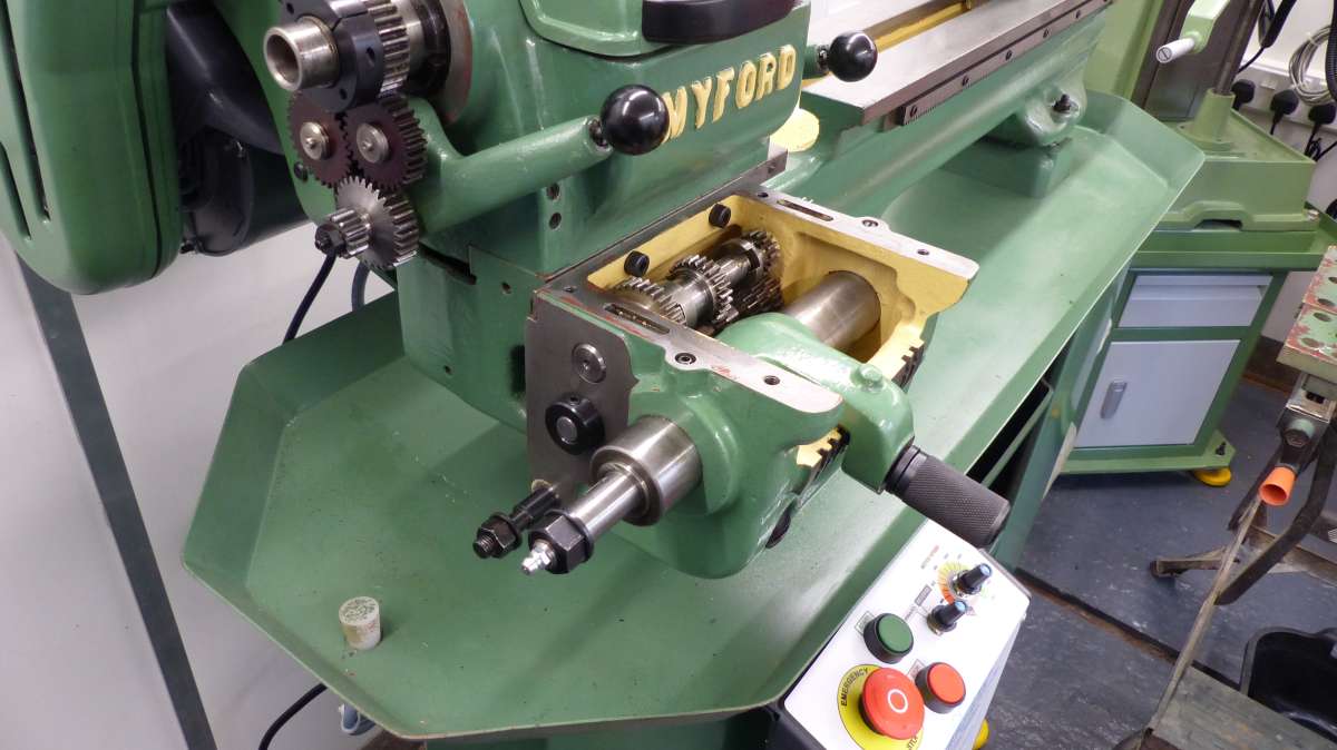
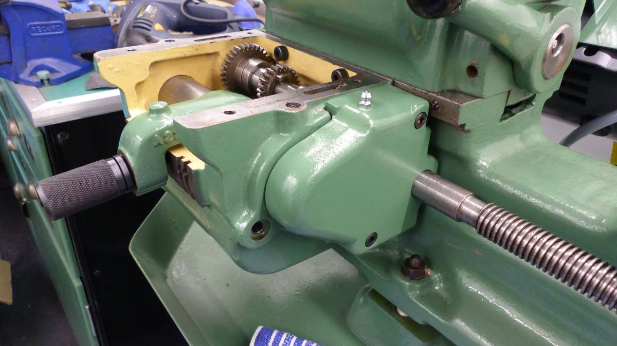
Gearbox as removed,showing external gearing used on early Gearboxes.
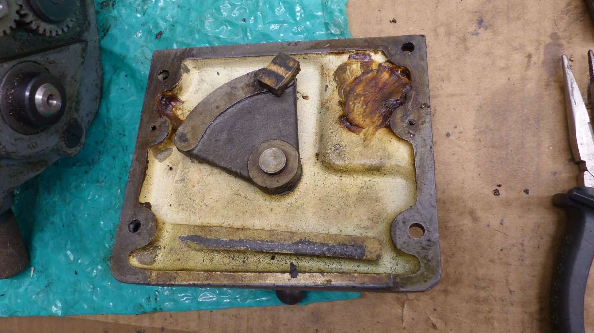
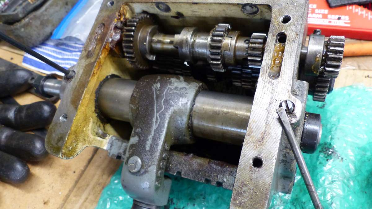
Inside of gearbox showing that it was well greased (?), and inside of box showing more grease and crud in oilways.
Some slight chipping of teeth evident, they where unhardened in the Mk.1 boxes.
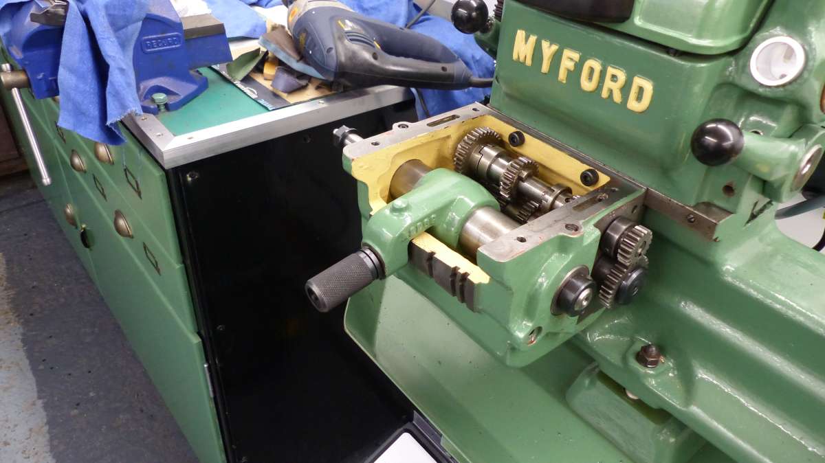
Gearbox cleaned and rebuilt and refitted ready for oil. left loose for now to facilitate clocking of top suface alignment with bed for leadscrew height.
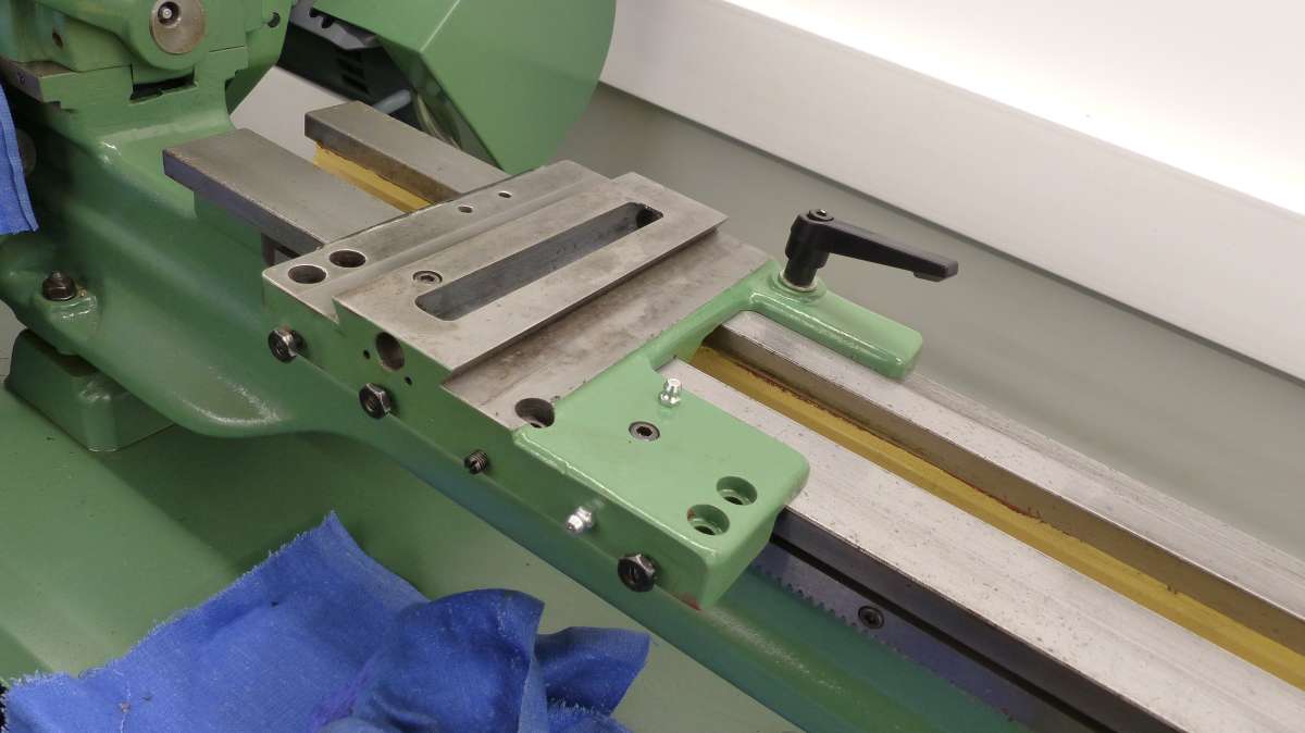
The Carriage refitted with updated locking lever. Gearbox end cover left loose on leadscrew while drive gear secured,then bolted in place.
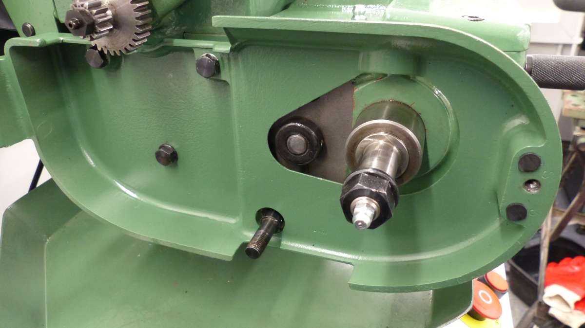
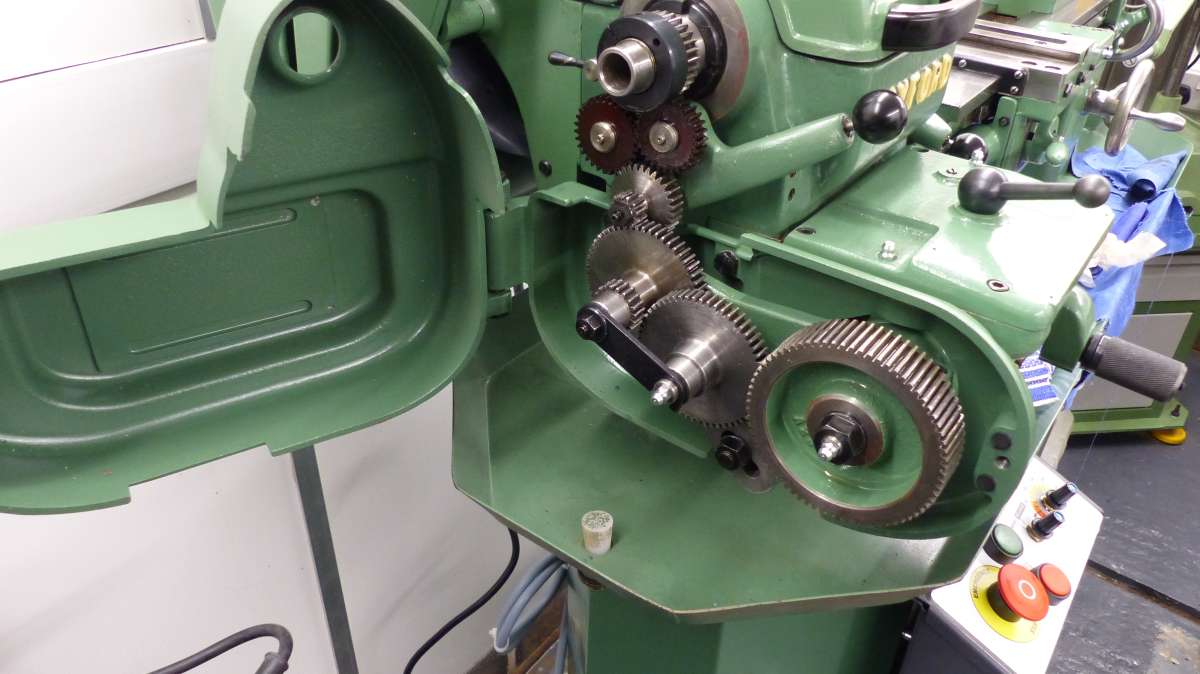
inner drive guard refitted,stud at bottom will have nut and washer fitted before locking stud into gearbox casing with grubscrew.
Outer guard re-hung on hinge pins,note rubber bumpers made from suitabe ‘O’ ring stock.
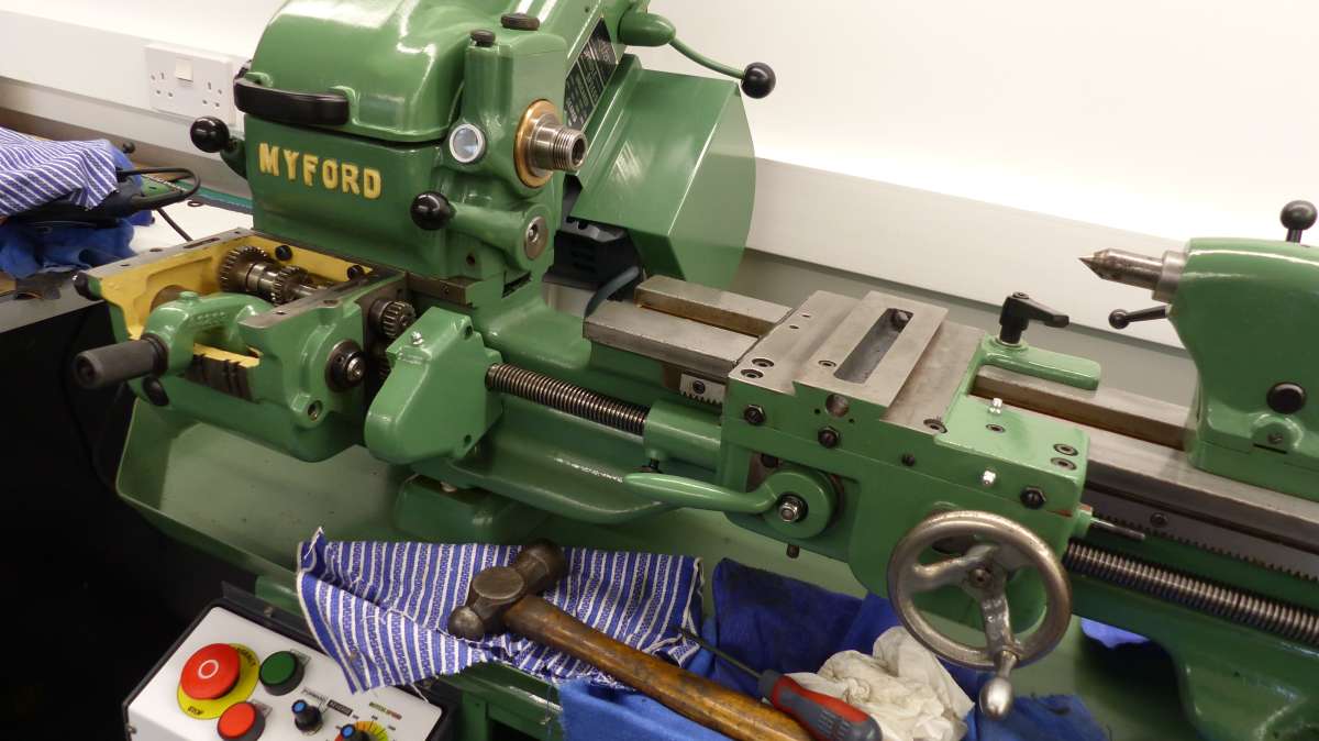
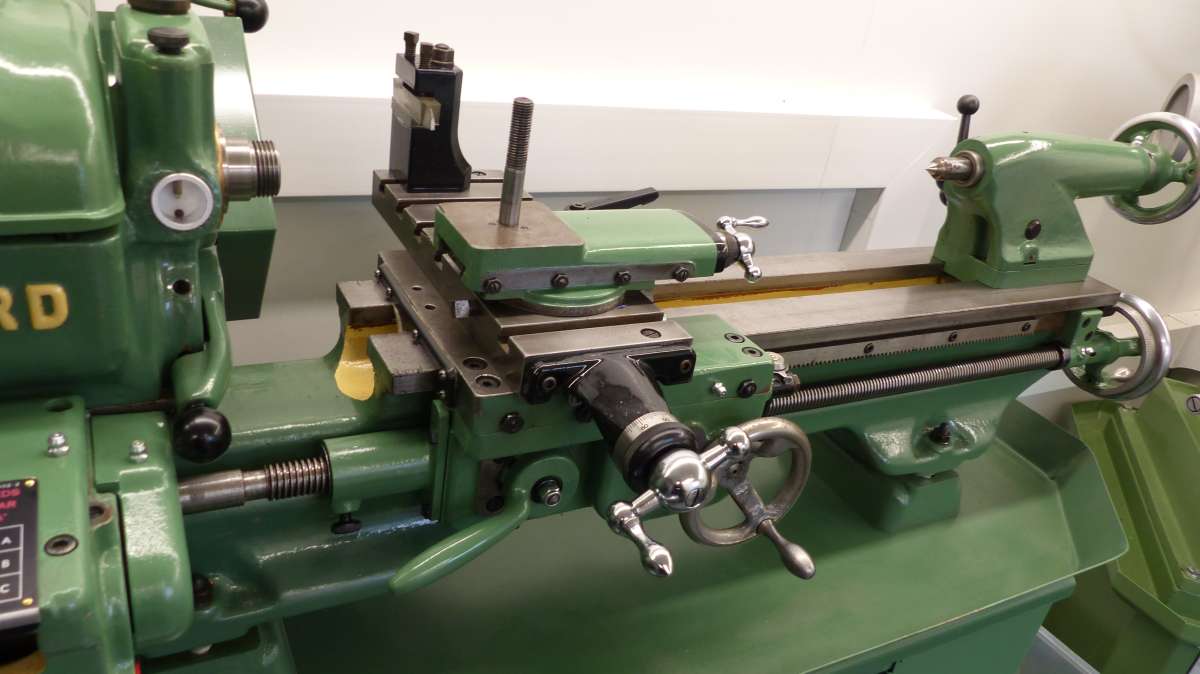
Carriage,saddle,cross slide and compound re-fitted, feed screws and nuts were all servicable. ball handles,retaining screws and micrometer dials were all beyond saving, so were replaced with new ones from Myford.
Saddle Handle will be replaced when I can get hold of one.
Note telescopic swarf guard on leadscrew, and Myford rear toolpost fitted.
I have sourced an original Dickson QC toolpost with a couple of tool holders but will need some more, has anybody tried fitting aftermarket (Chinese,Indian) ones, if so, do they fit the Dickson OK?
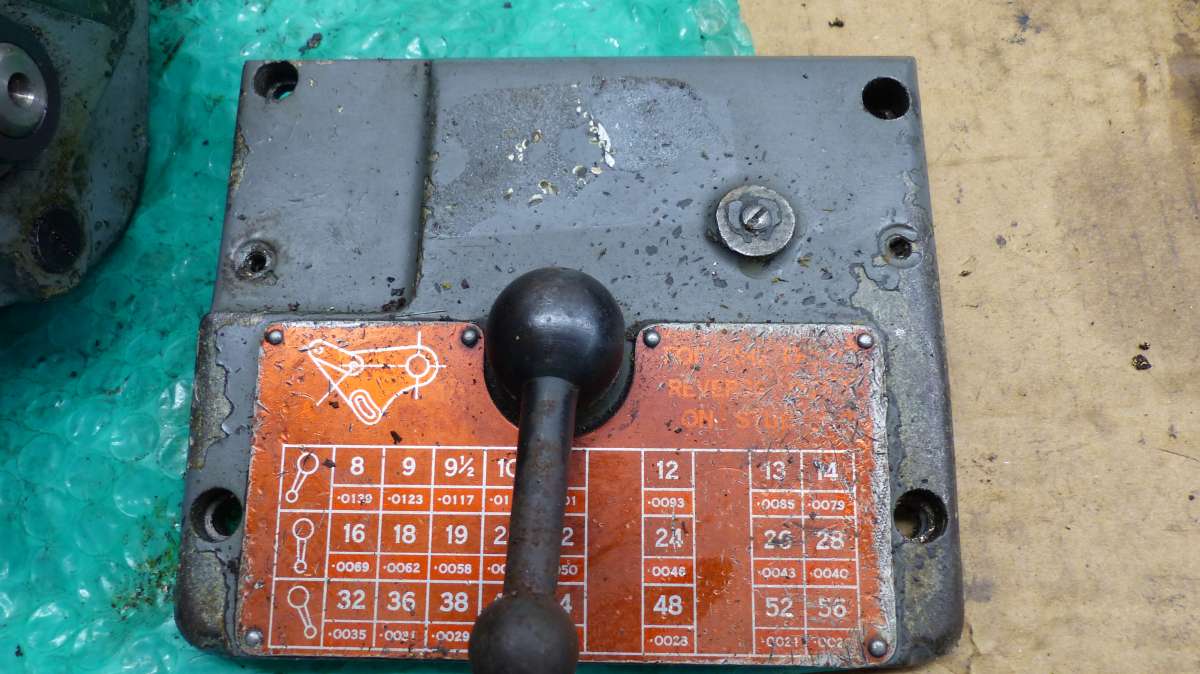
Job finished off with new dataplate on gearbox lid,the later boxes had the same plate, so I was able to get a replacement one.
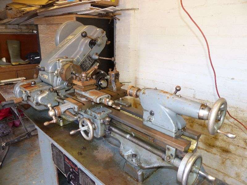
Last photo is a before refurbishment shot to show the work involved in bringing it back to life.
I have recently had surgery on My thumb for arthritis, so I am in plaster at the moment, but when i have recovered I will put down the floor tiles and fit a splashguard to the wall behind the chuck (which I have to clean up, 3 jaw and independant 4 jaw), and fit the nameplate to cabinet and pop the cork mats on the shelves.
I will put a new thread up detailing the workshop refit when it is complete.
Many thanks to everybody that has helped and followed Me along on this journey, I can only apologise for the length of time it has taken to get to this point, but as They say ‘Life has a way of getting in the way’!
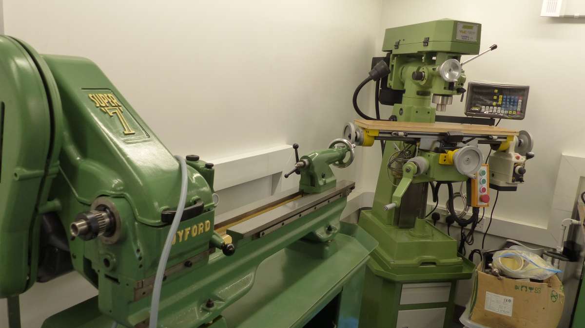
Looking forward to making lots of swarf, and getting to grips with the Miller as well!!
Seriously impressed! A friend has a similar age Super 7 in tatty condition, and I keep telling him we could make it nice – if we get to half that standard, we’ll be happy 🙂
Will refer back when we have to sort his clutch out.
Beautiful work! You’ve paid a great compliment to its original designers and builders!
Replying to Simon’s remark about lead-screws, way back up this thread, when I fitted my ML7 with a second-hand, early-pattern gearbox (as yours) I found it needs a shortened lead-screw.
Reluctant to alter the original lest it ever needed go back on, I bought a length of 3/4″ X TPI Acme “studding” from HPC gears and made a new screw to the requisite length.
Good luck with Your restoration,better working on a project together so You can keep each other motivated!
I split the job up into smaller jobs so I did not have too many parts loose at once, small compartmented boxes are good for keeping small parts and hardware sorted, I put a sticky label inside the lid with part number description on.
Strip.clean,paint and rebuild each section, then bring back together.
Take Your time with the clutch, parts are as rare as a Total Solar Ecilpse in the UK! Make sure You withdraw the clutch to the right as You remove the shaft to the left,it will only come off in one direction.
Try to replace bearings as You rebuild,needle rollers can replace the bushes on the countershaft and clutch,make sure You get the ones with a lubrication hole if required,and line them up with the oil nipples.
You will get the idea of how it works as You strip it down,for further information Google mk.1/Early Myford Super 7 Clutch. I have some information that was kindly passed onto Me,if You need anything,just get in touch.
Howard:-
Many thanks for the compliment,it’s been a long time coming,but worth all the effort (and many waves of the Magic Wand!)
Steve:-
Many thanks for You compliments!
I will start by Doing some projects from Harold Halls’ Lathework/Milling Course Books to get My hand back in, and I have some castings ‘Seasoning’ as We speak!
Nigel:-
Checked for leadscrew wear when I rebuilt,i cannot feel any slack in the saddle nuts which I was surprised about,but it is nice to know that 3/4″ Acme threaded rod is available if needed.
Again many thanks to Everybody for looking in and Replying!
When I had a ML7, swarf got into the motor and “Flash, bang”, at 2:00 pm on a New Years Eve!
Fortunately a local motor repairer was open, and the very kind chaps there cleaned up the centrifugal switch, so that the machine was up and running again by tea time.
Then I made an extenson cover for the motor, to prevent any repeat performances!
Considering what you started with you’ve done a beautiful job Morty. I see Jan Haugjord’s YT channel, his rebuilding skills and the Myford specific information he has on his channel has already been mentioned. But there doesn’t seem to be anyone yet mentioning this book. https://www.teepublishing.co.uk/books/in-your-workshop/model-engineers-workshop-manual/ Unless you already have it, then anyone with a ML or Super 7 lathe without question ought to have a copy. I don’t have either model of lathe, and still find it very useful.
Unless I somehow missed it, you haven’t had the bed, carriage, slide dovetails and tail stock base reground. I think this PDF https://pearl-hifi.com/06_Lit_Archive/14_Books_Tech_Papers/Schlesinger_Georg/Testing_Machine_Tools.pdf is about the best information you can find about the methods of testing and depending on it’s amount of wear, what you have verses what it should be close to. However, sometimes even free information can sometimes be costly in the directions it may lead you. 😉
Many thanks Pete. Sorry to hear about your health – hope it improves soon, and I look forward to your updates.
Which do you think is easiest: removing the spindle or removing the countershaft? Also, this may be a silly question but… how do you know if your rear headstock bearings need replacing?
Mike
As you have everything in bits replace them anyway 🥴
Back again Morty you must be very pleased on how the job has turned out. I should have mentioned much earlier before you did the painting. On my Super 7 cabinet I made some horizontal strips and welded them to the cabinet as runners for four sheet steel draws in which I keep some measuring things and lathe tools. Also, you might make a simple gadget/ edition to the lathe, which Brian Wood published in MEW and in his book some time ago, this will enable you to screw metric threads. John
Only just caught up with this thread and the entry from John Fletcher 1.
Unless an amendment was made by Brian Wood, he was not aware of the early gearbox with the aluminium cover at the tailstock end. No offence to Brian but his book does not cover that early model gearbox. He actually asked me if the box could be modified into the later version about which the answer is no, for anyone interested.
Thought this would be the best place to post this question – what size and section belt did you use for the motor to countershaft drive, please?
Thanks,
Rob
Not sure on the Super 7 but on my ML7 I used a common A section belt instead of the original Myford smaller ZZ or somesuch section. It just rides up a bit high in the V but it works and is more easily available than Myford’s original oddball small section belt. I forget the length but it’s easy to measure with a tape measure around the outside of the two pulleys then deduct one inch. Simple, but it works.
Thanks Hopper, good tip about how to measure as I’ve never been able to get that right. The belt is for a friend’s lathe, and I think should be 33.5 inches long according to a manual I found. However, we are swapping the motor, and I have found in my workshop a 34.5 inch Z section belt which I think I once bought in error, so we’ll try that next time I get to see the lathe. Might just do it if there’s enough adjustment.
Back again! Today, we fitted a replacement motor (off his power hacksaw!) and found the 34.5 inch belt will run it, but we will be getting the proper 33.5 inch belt as it’s on the limit of adjustment as it stands.
We then had a go at the clutch as it was slipping badly. Dismantled the whole countershaft, remembering to remove all screws and drive it out towards the tailstock. Not too bad a job, really. All bearings and bushes look good, and at this stage it’s a case of getting it working, any improvements scheduled for later. Unfortunately, the clutch ‘shoe’ only seems to be contacting at the two sections nearest the wedge – I assume this is due to wear over many years requiring over-adjustment causing it to be out of round. It does work OK, from free to locked with no slippage, but engages with a nasty grinding noise and a little puff of cast iron dust 😮 I did remove any burrs, etc before reassembly but to no avail
Any ideas? Just occurred to me whilst writing this, maybe filing a slight chamfer on the ends of the shoe (like we used to do with drum brakes to stop them grabbing) could help?
Final daft question – the clutch is supposed to run dry, isn’t it, with no lubrication on the shoe?
It’s no surprise to me that you have had no answers to your clutch question. The answer is, of course that it is just worn out and your chances of finding one are nil. I had the same problem many years ago and sourced a second hand modern clutch, for which you also need the larger outer belt guard. Never looked back, quiet operation and no slip from the off.
It’s no good filling even more off it as it is just not big enough now, circumference wise, but……Have you considered building the circumference up with something to just fit inside the space in the pulley? More or less a car brake pad infill. I am surprised that it has not broken due to being expanded too much anyway. I have no suggestions as to material or the means of fixing it but you must not weaken the expanding piece as a break really is the end. If you choose to rivet, then do it at the extreme open ends only.
I would have to suggest gluing something like a band of hard copper and if the disc really is miss-shaped, then filling the surface down to a circumferential (easy sliding) fit in the pulley, That way you can try a different material later if it wears out too quickly. It should not get hot but beware of it falling apart and giving sudden unexpected chuck motion. One answer to that is to leave it engaged if it can be made to work at all and just use motor on-off.
The clutch should run dry or slip would occur anyway, but the bearings have to be good or oil will get in. The original roller bearing had no oil seals.
This might prompt someone to come in with a better answer, like filling/milling up a replacement piece but that would be real work.
Thanks Dennis, I feared as much. It did occur to me whilst working on it that the pulley could possibly be bored out a bit and a sleeve Loctited in, don’t know if that would be any more efficient, but may be easier than adding something to the shoe. I guess the ‘out-of-round’ shoe would be the issue then, but it might just work. Some careful measuring required.
In the meantime, though, I think it’ll be a case of carrying on using it until it starts slipping again.
You are at or beyond the point where the shoe casting just snaps either side of the middle and I have yet to hear of anyone successfully attempting a weld. It is effectively cast iron.
The shoe started life not round. The ends are expanded out to grip the round annulus when the clutch is engaged. The nature of the fixed middle meant that the ends must must fall away sufficiently to be free of the pulley when it is disengaged. Your own idea of boring out the pulley and infilling with a ring is better than mine as it presents less danger of bits becoming unglued but you need another lathe to do that. Do nothing to the shoe in terms of altering it as most have already broken or become weakened such that they don’t fall away sufficiently and suffer creep like mine did, and don’t wait for it to break as it will.