Myford Lever Action Tailstock Design and Build

Advert

Myford Lever Action Tailstock Design and Build

Home Forums Manual machine tools Myford Lever Action Tailstock Design and Build

Viewing 23 posts - 126 through 148 (of 148 total)
  • Author
    Posts
  • #595065
    Hopper
    Participant
      @hopper

      Finally got out in the shed for an hour today and put it all together and actually drilled some holes. Result! And very nicely it works too. I like it particularly for centre drilling. Makes "pecking" much quicker and easier so you can bang it in pretty quickly and whip it out if it starts to complain. Likewise, very nice for small drills, although have not gone smaller than 1/16" at this stage. . Gives a good "feel" with the handle fully extended. I had thought half extended might be better for small drills, but seems the other way round. Longer handle gives more force with less effort, but more sensitive feel. ,

      Also really good for drilling a 1/4" hole a couple inches deep. Again the rapid "pecking" motion is much easier and quicker than with the handwheel. And it smashed a 13/16" (that's about 20.6mm)  drill bit through there like it was butter.

      The half-inch diameter handle seemed to stand up well with a tiny bit of flex, but less than the handles on my drill press so I am happy with that. Glad I made the sliding version though. Nice to tuck it out the way when not in use.

      The whole contraption looks like it has always been on there and not like some homemade afterthought, which was exactly the desired result. Very pleased I made the extra effort. It was worth it — in the end! But I may take a little break before starting on the small sensitive drilling attachment from the 1929 drawings.

      A big thanks to all those who contributed measurements, knowledge, ideas, articles and the like on this and related projects. I couldn't have done it without that vital input. And Noel many thanks for taking time out to get me "just one more measurement" several times!

      So look out for the full and complete drawings to be published in MEW in a future issue. (Can anyone suggest a good pencil to use? laugh )


      dscn0427.jpg


      dscn0424.jpg


      dscn0428.jpg

      PS. Notice that shiny little brass button there? That is perhaps proof that a good tradesman is not necessarily the one who does the perfect job every time, but knows how to cover up his clangers when he drops them. When I changed from the Plan A of the earlier threaded rod type of depth stop, and went instead with that later-type plain bar and small lock screw, I was left with an unwanted 1/4" UNC threaded hole already in the quill clamp. It looked rather lonely sitting there by itself for no good reason. So the piece of brass was turned down on one end and threaded and screwed into the hole. "Softens the impact of the stop without damaging the casting, sir. All the better ones do it."

      And look at that little ball handle in the last pic. Absolutely gorgeous. The cherry on top.


      Edited By Hopper on 19/04/2022 11:32:52

      Edited By Hopper on 19/04/2022 11:37:29

      Advert
      #595075
      Dave Wootton
      Participant
        @davewootton

        Lovely work and an excellent write up, makes me want to make one and I haven't got a ML7!!! but do feel inspired to make a ball handle for my saddle lock.

        Good luck with finding the correct pencil, I now know how critical these things can be, but after sticking a scriber in my finger yesterday I might be safer with crayons.

        Dave

        #595081
        ega
        Participant
          @ega

          Hopper:

          Congratulations on finishing the job! I hope that this thread and forthcoming MEW article will encourage others to adopt lever (or rack) feed.

          Two points about the brass button:

          Does it limit the travel of the ram?

          If you sometimes use gauge blocks to set the depth won't the button indent over time and affect the accuracy? A hardened button could be substituted.

          #595095
          Rod Renshaw
          Participant
            @rodrenshaw28584

            Thanks for this thread Hopper.

            Much more pleasant to read than watch a You tube type video.

            And such a good result, quite inspiring.

            Rod

            #595117
            bernard towers
            Participant
              @bernardtowers37738

              Hopper the depth stop bar on the original has a flat machined all along it, so it moves freely in the hole regardless of burrs raised by the screw.

              #595138
              David Davies 8
              Participant
                @daviddavies8

                Hi Hopper

                the device does indeed look as if it has always been on the lathe and the ball handled lever finishes it all off perfectly.

                BTW Prof Chaddock describes making the ball handled levers for the Quorn in his book using a form tool to produce the balls. Brave man!

                Thanks for a great read.

                Cheers

                Dave

                #595141
                Hopper
                Participant
                  @hopper

                  Thanks guys. Glad you enjoyed sharing in my shenanigans.

                  DW yes you have to watch those scribers. Rather surprising they don't come with an EU mandated cork stuck on the end these days.

                  Ega, all part of the design. The brass button does not limit travel, as the quill clamp is machined down to half thickness there and the brass just brings it back to full thickness. The later clamp was left full thickness in that area. Hardened button? I suppose if you were doing lots of repetition work, like making all your own BA fasteners for a loco etc in conjunction with a tailstock rotary turret attachment it could be a good idea. But I don't expect to use it that much. I can't remember ever needing to measure the depth of a drilled hole with any more accuracy than the graduations on the quill gave, so I reckon it will do me ok.

                  Rod, thanks. I too am not a great video person. Glad there are still some other readers left in the world!

                  Bernard, there is a flat on the stop bar. It just does not show in the photo. Pics earlier in the thread somewhere show how I filed it on there rather than milled. It's not quite the same depth as the original Myford but I think it looks the part and works fine. The end of the lock screw is machined to suit and minimise dents left in the bar. The a bar is made from a stainless rod out of an old printer but is actually surprisingly soft for stainless.

                  DD8, the old Prof was a braver man than I with his form tools. Sounds like chatter city to me. But he doubtless knew his stuff so might be worth a try sometime. Probably only worth the work of making such a wide form tool if you are making multiple ball lever handles, which I guess you are on the Quorn.

                  Cheers all.

                  Pete

                  #595166
                  Swarf, Mostly!
                  Participant
                    @swarfmostly
                    Posted by Hopper on 19/04/2022 23:32:26:

                    Thanks guys. Glad you enjoyed sharing in my shenanigans.

                    SNIP!

                    DD8, the old Prof was a braver man than I with his form tools. Sounds like chatter city to me. But he doubtless knew his stuff so might be worth a try sometime. Probably only worth the work of making such a wide form tool if you are making multiple ball lever handles, which I guess you are on the Quorn.

                    Cheers all.

                    Pete

                    Regarding ball handles and form tools:

                    There's a video on the web somewhere showing the use of a form tool to shave a ball handle. I've linked on this forum to that video a few times but, owing to a 'Reset Windows 10' catastrophe, I can no longer find the reference. It was stated that the shaving technique is often used in industry. From memory, the shaving form tool doesn't cut all at the same time but engages the workpiece progressively as the feed advances. It's quite fascinating to watch. Calculating the profile of the form tool must be quite complicated because the angle of presentation is non-intuitive.

                    Best regards,

                    Swarf, Mostly!

                    #595170
                    noel shelley
                    Participant
                      @noelshelley55608

                      Hi Pete, It was a pleasure to offer what help I could, that what's I view this site as and for. The job looks great ! The brass pad was divine intervention ? In my innocense when I bought mine I failed to realise that it needed a long barrel for the tailstock – this was missing ! One day I will get round to making one ! Best wishes Noel

                      #595173
                      Hopper
                      Participant
                        @hopper

                        Thanks Noel. Yes the help I have had off this site in years is priceless.

                        Yes divine inspiration to get rid of that hole and dress it up with a bit of brass at the same time.

                        Long barrel for the tailstock?? Is that the round ring the S7 needs in the pics I have seen?

                        Swarf Mostly: Don't you just love Windows 10 and its "upgrades"? I can usually tell when one is coming up, my computer slows down for half a day while it downloads then announces I need a restart. Grrrr! I do vaguely remember something about shaving form tools now you mention it. Basic principle sounds right, it cut on different parts as it was fed in but can't remember how it was executed in practice. I shall have to have a bit of a look around for what I can find. It was probably common practice on the capstan lathes of yore cranking out metal widgets before plastic took over. But that generation of toolmakers and toolsetters is just about gone I am afraid. And with them the knowledge.

                        #598805
                        Hopper
                        Participant
                          @hopper
                          Posted by Hopper on 31/03/2022 11:07:54:

                          Which brings to mind the ball that goes on the end of the handle. Looks in some pics like it would be 1-1/2" diameter, in others maybe a little smaller. And some pics seem to show a taper on the lever leading up to the ball. I will probably order a bag of five 38mm (1-1/2" ) black plastic machine knob balls off eBay for peanuts. .But they will have to come from Hong Kong and there is a two month imports backlog at Customs due to Covid. We are sort of at the peak of the Covid wave right now that the UK went through some months back.

                          Hey look at what arrived in the mail today:

                          dscn0760.jpg

                          It only took 7 weeks! But now I am quite used to using the aluminium "temporary" ball I made, so will not bother to rethread the handle to fit one of these. I have a couple of other projects in mind that I can use them on. (Leadscrew dog clutch being one of them.)

                          Meanwhile, I have been giving the new lever tailstock a good workout, and I am loving it. Have been drilling many holes in the lathe ranging from about 1/16" to 11/16" for various jobs and some small sensitive centre drilling too. Once I got used to not having the handwheel there to grab to slide the tailstock along the bed, the lever version seems to be superior for all purposes, whether drilling, tapping, running a live centre or a dead centre etc. So the lever has officially become a permanent fixture on my lathe.

                          In fact, I like it so much I have made good progress on making a little brother for it, using a 0-4mm chuck for extra small sensitive drilling jobs, and a taper spindle that can be quickly whacked in and out of the tailstock quill when and as needed.

                          dscn0799.jpg

                          #598807
                          ega
                          Participant
                            @ega

                            Hopper:

                            It's good to know that your project has worked out well in practice and to be hoped that it will inspire others.

                            May I ask what length of travel you achieved with your lever feed? I saw a suggestion that 94mm was possible but I don't get anything like this with my Super 7 version.

                            #598809
                            Hopper
                            Participant
                              @hopper

                              Thanks ega.

                              Length of travel on my lever tailstock is about the same as with the standard arrangement, maybe a half or quarter inch or so less. The quill has to stick out the back of the tailstock casting that little bit for the quill clamp to grip on to. But it will extend the quill out beyond the engraved lines on the quill, which I think is two or two and a half inches. Which is plenty for me. You can always slide the tailstock along for deeper holes. You could probably get a half inch or bit more out of it by making a stepped quill clamp that slid inside the tailstock body recess where the original handwheel fitted. But it's not something I thought important at the design stage.

                              I think to get anything like 94mm you would have to use the capstan style tailstock with the rack and pinion mechanism and lot longer quill. Someone mentioned making one of tose out of a small car rack and pinion steering box. But that's a whole nuther can o' worms!

                              #598812
                              ega
                              Participant
                                @ega

                                Hopper:

                                Thank you. I get about the same travel as you and think that the 94mm I saw must have been a mistake.

                                With rack and pinion, of course, the travel is potentially only limited by the available space.

                                #626737
                                Hopper
                                Participant
                                  @hopper

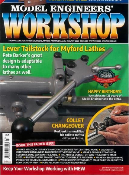
                                  And here it is, front page of Model Engineers Workshop 323. Our 15 minutes of fame at last. Thanks again to all those who contributed knowledge and dimensions, and encouragement, and made it possible.

                                  One little update after seven months of use: The lever tailstock is still a permanent fixture on my ML7. Never had need or even thoughts of changing back to the old handwheel. The lever works a charm for everything I do. I am glad I went with the sliding handle version, partly so it can be tucked out of the way when not in use, but also so it can be used short for small drills and gives great sensitivity and fast pecking action. 100 per cent chuffed with the whole thing. Well worth the effort of making.

                                  mew 323.jpg

                                  #627832
                                  Douglas Johnston
                                  Participant
                                    @douglasjohnston98463

                                    Hi Hopper – very much enjoyed reading your article in the latest copy of MEW and have been inspired to make one for my Myford Speed 10. I may have to alter the odd dimension to fit the Speed 10 but it looks like it will work. One thing you did not mention in the article was the hole spacing on the flat bar link, what did this turn out to be ?

                                    Doug

                                    #633545
                                    Hopper
                                    Participant
                                      @hopper
                                      Posted by Douglas Johnston on 06/01/2023 11:24:23:

                                      Hi Hopper – very much enjoyed reading your article in the latest copy of MEW and have been inspired to make one for my Myford Speed 10. I may have to alter the odd dimension to fit the Speed 10 but it looks like it will work. One thing you did not mention in the article was the hole spacing on the flat bar link, what did this turn out to be ?

                                      Doug

                                      Sorry Doug, I missed your post until now. The distance between the hole centres on the link is 2-1/4" .Yes I think you could adapt it to the Speed 10 with minimal changes to suit the diamter of your tailstock body.

                                      The final section of the article, along with the drawings for the link, handle, clamping ball handle and the stop are all in the next edition of MEW, Issue 324, February, which is out now. I did not realise the article had been split into two until just now because they take months to reach me in rural Australia.

                                      #633549
                                      Ady1
                                      Participant
                                        @ady1

                                        Nice one Hopper, well done you

                                        You're now a social media star and can appear on I'm a celebrity and strictly come dancing

                                        #633550
                                        Hopper
                                        Participant
                                          @hopper
                                          Posted by Ady1 on 15/02/2023 10:24:40:

                                          Nice one Hopper, well done you

                                          You're now a social media star and can appear on I'm a celebrity and strictly come dancing

                                          Thanks Ady.

                                          laugh Mate, the only dancing I do is when a bit of hot swarf lodges between two toes when I am wearing flip flops in the workshop in summer!

                                          #633556
                                          Douglas Johnston
                                          Participant
                                            @douglasjohnston98463
                                            Posted by Hopper on 15/02/2023 10:10:11:

                                            Posted by Douglas Johnston on 06/01/2023 11:24:23:

                                            Hi Hopper – very much enjoyed reading your article in the latest copy of MEW and have been inspired to make one for my Myford Speed 10. I may have to alter the odd dimension to fit the Speed 10 but it looks like it will work. One thing you did not mention in the article was the hole spacing on the flat bar link, what did this turn out to be ?

                                            Doug

                                            Sorry Doug, I missed your post until now. The distance between the hole centres on the link is 2-1/4" .Yes I think you could adapt it to the Speed 10 with minimal changes to suit the diamter of your tailstock body.

                                            The final section of the article, along with the drawings for the link, handle, clamping ball handle and the stop are all in the next edition of MEW, Issue 324, February, which is out now. I did not realise the article had been split into two until just now because they take months to reach me in rural Australia.

                                            No problem Hopper, I picked up on the second part of the article which I also was not expecting and saw the dimension there.

                                            Doug

                                            #635437
                                            john Chappell 1
                                            Participant
                                              @johnchappell1

                                              John Chappell

                                              Has anyone modified a Super 7 ?

                                              #635439
                                              Hopper
                                              Participant
                                                @hopper
                                                Posted by john Chappell 1 on 01/03/2023 03:45:48:

                                                John Chappell

                                                Has anyone modified a Super 7 ?


                                                The Myord lever tailstock is the same for both ML7 and Super 7. But the Super 7 requires a threaded stepped ring that screws into the back of the tailstock and the regular lever attachment clamps on to that . I don't have the details as I don't have access to a Super 7. There is good info including a drawing in this thread though LINK

                                                Edited By Hopper on 01/03/2023 03:56:56

                                                #637848
                                                john Chappell 1
                                                Participant
                                                  @johnchappell1

                                                  Thank you, I will look it up.

                                                Viewing 23 posts - 126 through 148 (of 148 total)
                                                • Please log in to reply to this topic. Registering is free and easy using the links on the menu at the top of this page.

                                                Advert

                                                Latest Replies

                                                Home Forums Manual machine tools Topics

                                                Viewing 25 topics - 1 through 25 (of 25 total)
                                                Viewing 25 topics - 1 through 25 (of 25 total)

                                                View full reply list.

                                                Advert

                                                Newsletter Sign-up