Myford Lever Action Tailstock Design and Build

Advert

Myford Lever Action Tailstock Design and Build

Home Forums Manual machine tools Myford Lever Action Tailstock Design and Build

Viewing 25 posts - 26 through 50 (of 148 total)
  • Author
    Posts
  • #590085
    Hopper
    Participant
      @hopper

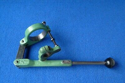
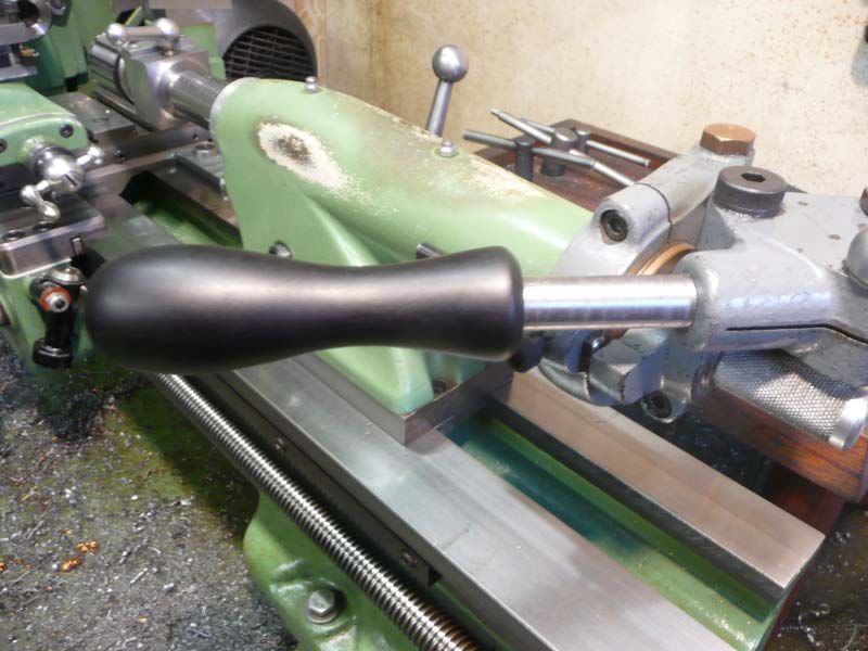
      Blowing this pic up on screen until the overall handle length is 12" (roughly full size) , the distance between the two pivot bolts on the handle measures 3", so pretty close to double the 1.625" on Noels later type. Interesting. I might have to go for the harder to make later type and get more leverage for poking that 1" drill through 3/4" plate next time.

      myford-ml7-tailstock-lever.jpg

      Noel, notice the different type of stop on this one. That's where the tapped hole in the quill clamp came from on mine. We'll see how it works in practice. Can always drill out and fit the larger 5/16 plain shank with pinch bolt later.

      Edited By Hopper on 16/03/2022 10:22:14

      Advert
      #590087
      Dave Wootton
      Participant
        @davewootton

        Thanks Noel always wondered if that was a Myford part, interestingly the ones in the pictures show a replacement plain tailstock spindle, mine just clamped over the threaded part of the original ML7 tailstock quill. It was secondhand so maybe that just didn't come with it, worked fine with the standard ML7 quill.

        Please keep up the post's Hopper, always interested in a build log, there's always something to learn and an " why didn't I think of that moment". Also interested if you build one for your Drummond, I had an M type years ago that i stupidly sold to buy a Cromwell S800, lovely lathe but couldn't get on with it, one day I'll get myself another M and rebuild it along with all the mod's and accessories that I've seen for them. Eeking out my redundancy money untill I get my pension this July, so no toys at the moment!

        Dave

        #590089
        Hopper
        Participant
          @hopper

          OK, so slow progress today, on several accounts. The termite exterminator man came this morning to do an inspection 12 months after he sprayed for termites that were eating away at my wooden shelving and storage boxes in the workshop. All clear. He is a North Queensland old timer so we spent about half an hour checking for termites and another hour chinwagging and solving the world's problems. He's a lovely bloke.

          Then it started raining buckets so no chance of finishing off the quill clamp on the outdoor linishing belt.

          I wish I could train those termites to eat metal along a straight line as I had some trouble doing the same on the 3/4" thick steel tailstock body clamp I carried on with. I tried milling the 1/4" slot in it for the 3/4" x 1/4" link to fit into. But either the 3/4" plate was too solid and the cutter too flimsy, under the less than rigid conditions of using the vertical slide on the ML7. Either that or I was too heavy handed with it. Possible, as the last milling machine I used was a big old Cincinnati that weighed 19,000 Lbs, and that was some years ago. But despite my best efforts taking a 1/8" deep cut across the 3/4" plate, just as it broke out the other side, the cutter started sparking and jumping around and growling like an unregistered dog. I backed off the hand feed but as soon as I tried again the cutter clean snapped in half.

          The broken cutter shown here with the completed slot it did NOT cut:

          dscn0073r.jpg

          So it was back to Plan A and I drilled a 15/32 hole where I wanted the end of the slot to be and made two careful cuts with the bandsaw, in horizontal mode with the job held in the vice. With a brand new blade in it to replace the Chinese original it cut straight as a die and I reckon I only had to file out way less than 10 thou to make it a nice fit on my piece of 1/4" flat bar for the link. Beautiful. Fits in there like a glove.

          dscn0074.jpg


          So now it is starting to look like I have something:

          dscn0075.jpg

          Which is always encouraging. And I will probably need it tomorrow with the task of bandsawing that 3/4" steel plate into a nice curvaceous looking facsimile of the original Myford casting. Tossing up between whether to wimp out and just make it all straight cuts done in the vice, or get fanatical and keep trimming it down into curves then finish it off with the angle grinder and linishing belt. A lot of work. We'll see what the morrow brings.


          Edited By Hopper on 16/03/2022 11:04:52

          #590092
          Hopper
          Participant
            @hopper
            Posted by Dave Wootton on 16/03/2022 10:55:26:

            Thanks Noel always wondered if that was a Myford part, interestingly the ones in the pictures show a replacement plain tailstock spindle, mine just clamped over the threaded part of the original ML7 tailstock quill. It was secondhand so maybe that just didn't come with it, worked fine with the standard ML7 quill.

            Please keep up the post's Hopper, always interested in a build log, there's always something to learn and an " why didn't I think of that moment". Also interested if you build one for your Drummond, I had an M type years ago that i stupidly sold to buy a Cromwell S800, lovely lathe but couldn't get on with it, one day I'll get myself another M and rebuild it along with all the mod's and accessories that I've seen for them. Eeking out my redundancy money untill I get my pension this July, so no toys at the moment!

            Dave

            Haha, I am familiar with that type of financial scenario. I dont know that I will make a second one for the Drummond M Type. Maybe buy the castings of the IO group when shipping to Australia returns to normal. I like the old Drummond. It is a more accurate lathe than my ML7. Very very good for small precision work. But the smaller spindle and bearing diameter make it more limited for bigger heavier jobs. The spindle has been chewed up where the pulley rotates in back gear so one day I will get around to making a larger diameter spindle out of 4140 and boring out the bearings to suit, as per Shrubsole or Jenkins or someone did in ME/MEW years ago. I have the article on file , just waiting for the day. Will machine the flat belt pulleys to take Poly-V belt at the same time.

            Edited By Hopper on 16/03/2022 11:14:41

            #590176
            noel shelley
            Participant
              @noelshelley55608

              Hi Hopper The angle you suspected was there is 12* to the rear (away from the headstock). Hope this helps. I have sent a PM. Dave, the plain tailstock spindle is the new S7 type.  One thing that is seldom mentioned is the use of ROTABROACHES to make large holes, they go from 11mm to at least 50mm. Noel.

              Edited By noel shelley on 16/03/2022 17:13:19

              #590235
              Hopper
              Participant
                @hopper

                Thanks again Noel. I will have a sit down with the scrap box and see what can be fabricated to duplicate the handle casting part.

                Yes I thought of rotabroaches several times while boring out that hole. But sadly I have none. My mate picked up a boxfull at the dump that someone had thrown out just before he arrived to dump an old lawnmower. I never seem to have that kind of luck! I reckon a 50mm job might put a bit of strain on that little key in the Myford tailstock keyway though.

                #590241
                ega
                Participant
                  @ega

                  A small but worthwhile feature of the Rotabroach or similar is that particularly when used without a pilot they produce a useful slug of material on completion of the cut.

                  I take the point about the strain on the keyway but, of course, size for size they produce less chips than drilling/boring; the chips, however, are long and curly. Incidentally, it seems possible that using them with the lever feed tailstock would allow the lever to react some of the torque.

                  #590243
                  Hopper
                  Participant
                    @hopper

                    Yes probably less torque than that 1" drill bit I used when you think about it. And you could always use the old time machinists dodge of putting a lathe drive dog around the drill or rotabroach shank with the tail bearing against the carriage to take the load off the tailstock key.

                    #590245
                    David-Clark 1
                    Participant
                      @david-clark1

                      Ian Bradley (half of Duplex partnership) published full designs in Model Engineer back in the 1950s.

                      #590257
                      Hopper
                      Participant
                        @hopper

                        Thanks David. I'll look it up. I have Bradley's book "Lathe Devices" which includes drawings of a more upmarket model that allows you to keep the tailstock handwheel in place but I decided I prefer the standard Myford type. Not sure if the one in the book is the same as the ME article. And Geoff Walker did a remake of this one in MEW a couple of years ago and I have those drawings, but it is a different arrangement altogether frrom the stock Myford unit.

                        A quick check reveals the index shows a pair of Duplex articles on making a lever tailstock for Myford in 1952 in Volume 106, issues 2654 and 2656. The latter includes full drawings, it says. No mention of it being the one that retains the handwheel. So I shall see if I can track down copies of those issues,, or someone who can scan a copy for me.

                        Thanks for the tip.

                        I made good progress today on bandsawing the outline, despite battling several pieces of substandard Chinese machinery along the way. Will post some pics after dinner. Hungry work running that bandsaw.


                        Edited By Hopper on 17/03/2022 09:23:11

                        #590267
                        David-Clark 1
                        Participant
                          @david-clark1

                          Hi Hopper

                          That brings it back I think.

                          I believe it does leave the original hand wheel intact. I think where the half plate holds them wheel in place there is a shaped piece that can pivot out of the way to release the hand wheel. Only applicable to the old style Myford tailstock with the large round back end.

                          I believe Duplex did other tailstock attachments including a powered one possibly for a Myford M series or maybe a Drummond. M Lathe. I can see it in my mind but not the make of lathe.

                          #590268
                          David-Clark 1
                          Participant
                            @david-clark1

                            Hi Hopper

                            You could drill the outline and knock the waste off.

                            Then finish with a file.

                            #590279
                            Hopper
                            Participant
                              @hopper
                              Posted by David-Clark 1 on 17/03/2022 10:03:27:

                              Hi Hopper

                              You could drill the outline and knock the waste off.

                              Then finish with a file.

                              Yes that's the way I have done it in the past but my days of cold chiselling and filing are well and truly over. Just can't do it anymore. So I have this fancy new Chinese bandsaw that takes all the manual labour out of it. I'm loving it.

                              Yes the Geoff Saunders remake of Duplex design has the removeable half plate on a pivot, that's the one.

                              #590281
                              Keith Long
                              Participant
                                @keithlong89920

                                Hi Hopper

                                I've sent you a PM.

                                Keith

                                #590283
                                ega
                                Participant
                                  @ega

                                  Hopper:

                                  I realise that you are reproducing the Myford item but may I commend a more comfortable style of handle?

                                  p1030646.jpg

                                  #590285
                                  David-Clark 1
                                  Participant
                                    @david-clark1

                                    Hi Hopper

                                    I new I had seen other lever feeds in the past. I can usually remember most of the articles in ME over the years but not all the fine details.

                                    For instance I remember a nice little drilling/ boring machine based on two bars like the original Unimat SL just by thinking about back issues.

                                    it is al in my head, I just have to reindex it.

                                    unfortunately I can no longer read the small text in the old MEs by I do have a lot of the early ones on PDF that I can read. Only just remembered I have got them.

                                    That is why I like posting on the forum. As well as helping otes it helps me remember for myself.

                                    No I am not senile, just old.

                                    i knowwhat senile feels like. I thought I was losing my mind a while back. I was trying to remember lots of things and was completely confused. I eventually put it down to lack of food and weakness.

                                    The trouble is I rarely feel hungry and am concentrating so much I forget to eat.

                                    #590290
                                    Hopper
                                    Participant
                                      @hopper

                                      A slow morning and a better afternoon today. This was the sum total of the morning's work:

                                      dscn0084.jpg

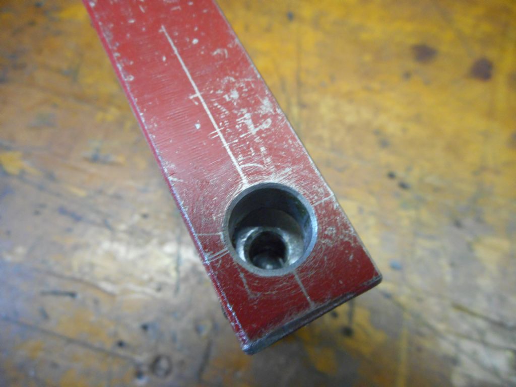
                                      One hole drilled, and one half of it tapped 5/16 UNF (that's what taps I have) for the end of the main pivot bolt. Other half reamed out to 11mm, the nearest reamer I have to Noel's 7/16 pivot pin dimension.

                                      Why all morning to drill tap and ream one hole? Well, the last hole in another job I did came out oversize and crooked so decided I had better give my Chinese Craftmaster drill press a bit of a looking at before destroying all my work so far with a duff hole. A quick check revealed my reamer running about 15 thou out of true. Yikes! So back to basics. Cleaned the chuck taper and put a dial indicator on the bit taper sticking out of the drill machine spindle. All good there. No discernable runout. Maybe one tenth of a thou or so.

                                      Then put the dial indicator on the shank of the reamer, a Chinese "chucking reamer" with plain parallel shank. Oh oh. About 8 thou runout there. And that was with my good quality keyless chuck from Australias top reputable supplier Hare and Forbes. So swapped a few different chucks but did not see much improvement. So tried a carbide milling cutter shank instead of the reamer and hey presto, only two thou runout next to the chuck. Not great but acceptable for a drilling machine I suppose. That was with my best Rohm brand chuck.

                                      So it looks like those Chinese chucking reamers are a) not ground round on the shank by several thou and b) the shank does not run true to the cutting edges. Obviously designed to be used only in a floating reamer chuck that lets it move about and follow the hole. So I managed to find one combination of 11mm reamer and chuck that ran acceptably true by putting the chuck runout one way and the reamer runout the the other. I have some good old UK made reamers with morse tapers that run dead true but of course all are too big or too small for this job.

                                      So onward to why the previous reamed hole was crooked. Turned out the table on the drill press has sagged, again, and needed shimming to bring it back to level. And measured that tightening the table clamp around the vertical column creates 40 thou of lift at the table edge. A result of poor design where the clamp around the column is split all the way along to allow the clamping action. My old Aussie made drill press had the same clamp split only about one third the way, so the remaining two thirds forms a good bearing surface and the other one third does the clamping. Why the Chinese could not do this, i do not know. I may put a new motor on the old drill press and bring it back out of retirement.

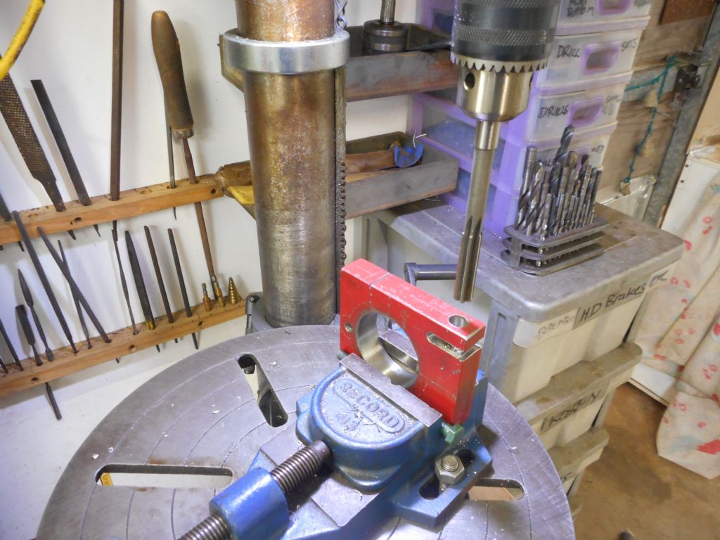
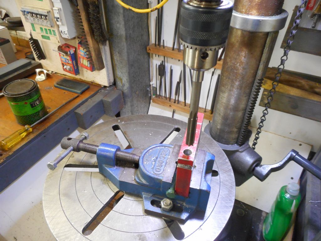
                                      Anyhow, onward through the fog in the afternoon and got a fair bit done. I drilled and tapped all the other holes for the tailstock body clamp and also drilled four or five holes where I wanted a small radius on the finished profile. Did this all while the block was still square shaped so it was easier to hold in the drill press vice.

                                      dscn0081.jpg

                                      Used a long bolt between the moveable jaw and job to ensure it pressed up against the fixed jaw and so stood up vertical.

                                      dscn0078.jpg

                                      #590291
                                      Hopper
                                      Participant
                                        @hopper

                                        So then it was time to start bandsawing the outside shape of the tailstock clamp. Mostly this was done by cutting various straight lines with the job held in the bandsaw vice. I can then just sit there and watch it do all the work. Had a bit of a battle with the vice jaws on the Chinese bandsaw not being square in the vertical plane so had the job move a couple of times, so had to feed the blade through carefully by hand so it did not move the job. Disappointing that they go to all that effort to make a machine tool and then let poor machining like that mar its performance. The vice jaw is very thin too, about 6mm cast iron in place. I may screw a 6mm plate to it and get a mate to mill it properly square for me on his mill. It's too big to do in the Myford.

                                        But the straight cuts in increments worked well, with the few 5/16 holes for radiuses where needed. And I touched up a few twiddly bits by hand in vertical bandsaw mode. Always amazes me that posting a pic of my old Drummond lathe with no belt guards or change gear covers brings howls of protest and warnings about safety etc and yet stuff like this is socially acceptable:

                                        dscn0086.jpg

                                        It gives me the willies having my fingers that close to a whirring blade. And yes I know there is a bolt on larger table for this type of use, but the hole in the middle of it where the blade runs is so big that small jobs — or small offcuts like this bit — threaten to disappear down it, taking fingers with them. So for this quick bit, did it this way.

                                        IN the photo I am just finishing off the last little bit between two cuts done in the vice, but because the blade pivots and cut at an angle, two cuts never meet squarely through the full depth so have to finish it like this.

                                        A happy afternoon was spent watching metal filings being made by the sawblade until the final shape of the clamp began to almost emerge from the solid block:

                                        dscn0090.jpg

                                        It was a bit of a juggling act. The more you cut off, the less there is left to grip in the vice. So I will leave the big chuck on the right until after I have done two or three more straight cuts down on that narrow bottom section. Then the coup de grace will be the straight cut form that 5/16 hole along that straight scribed line to freedom. I didnt complete the cut at the top which will become the gap in the clamp just yet, so the job is still one solid peice and easier to hold in the vice.

                                        You can see my "layout red" has endured well, after copping a good hiding in all the in and out of the vice and drilling etc. Felt pen would be long gone and $50 Dykem not too far behind it. The red paint will do me.

                                        That last cut will be the major hurdle over and done with. Then on to the belt linisher, which is as scary or scarier for fingers as that vertical bandsaw set up, and the angle grinder to round off all the square edges and give it the "faux casting" look. I thought about just leaving it all as a square chunk, or a square chunk with the corners lopped off but that always looks so unfinished to me. An extra day's easy work rounding the shapes is well worth the effort in the long run, I reckon. And as a piece of tooling, round edges are so much easier on hands and knuckles than angular flats and corners.

                                        Noel, I also drilled the hole for the pinch bolt on the depth stop like your model has, so I can go with that type if I want to in the future. Figured it easier to drill it now while the block was still square to grip in the vice.

                                        Edited By Hopper on 17/03/2022 11:43:54

                                        #590336
                                        David-Clark 1
                                        Participant
                                          @david-clark1

                                          Hi Hopper

                                          Looks like you are getting there.

                                          I think a lot of drill presses are deliberately machined so the table is not flat because they bend down from the pressure of the drill.

                                          I would probably do that reamed hole in a mill by drilling an undersized hole and boring with a 7/16 old end mill or slot drill before finish reaming or boring.

                                          If you have a slightly undersized slot drill you can get the size perfect by shimming out with a bit of very thin paper in the colletto make it cut larger.

                                          #590337
                                          David-Clark 1
                                          Participant
                                            @david-clark1

                                            Hi Hopper

                                            Looks like you are getting there.

                                            I think a lot of drill presses are deliberately machined so the table is not flat because they bend down from the pressure of the drill.

                                            I would probably do that reamed hole in a mill by drilling an undersized hole and boring with a 7/16 old end mill or slot drill before finish reaming or boring.

                                            If you have a slightly undersized slot drill you can get the size perfect by shimming out with a bit of very thin paper in the colletto make it cut larger.

                                            #590392
                                            Hopper
                                            Participant
                                              @hopper

                                              Yes, it might be the excuse I need to buy that new Sieg SX3 mill I need in my life.

                                              Although, it is a heavy drill press and should not distort drilling and reaming a 5/16 etc hole. Just poorly designed in the column clamp area and poorly machined in the table mount, ie not square and needed shimming from new.

                                              But a milling machine would definitely be nicer.

                                              No progress today. Rest day. I run out of chuff pretty quick these days. (Another reason to buy a mill and let it do all the work!)

                                              #590596
                                              Hopper
                                              Participant
                                                @hopper

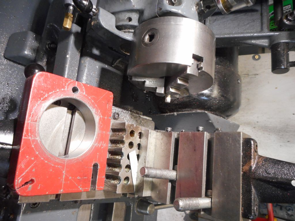
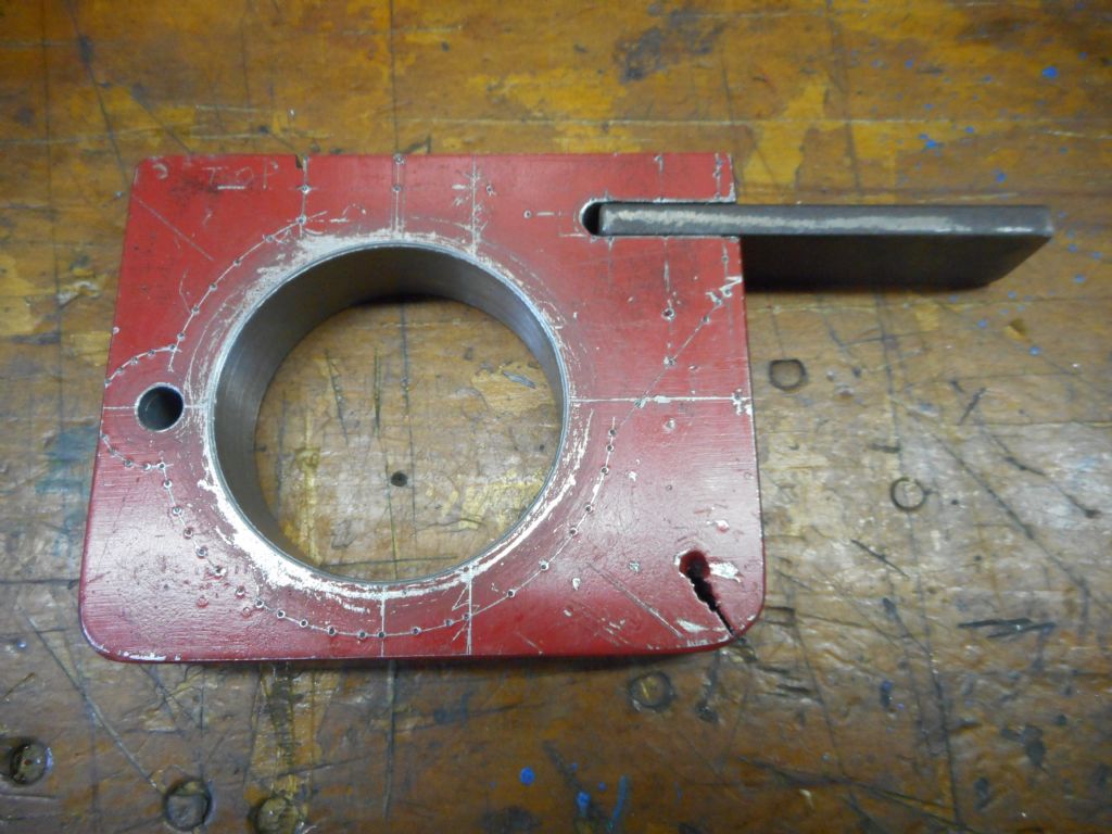
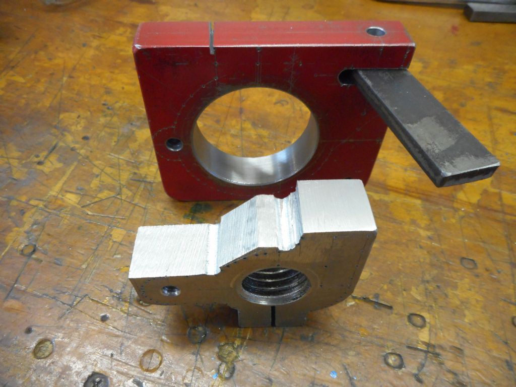
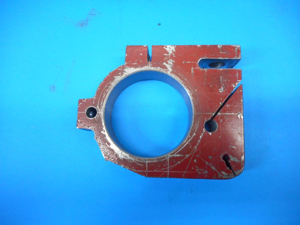
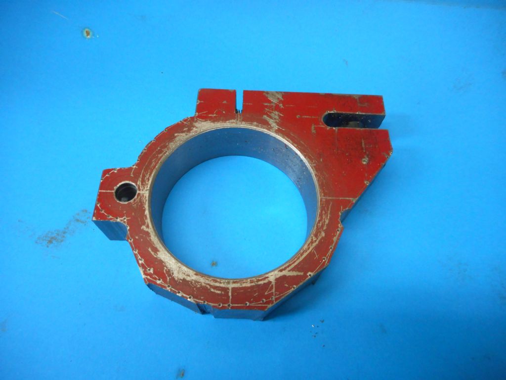
                                                I got to the end of the bandsawing today. And lo and behold! I knew there was a tailstock clamp burried in that piece of steel plate somewhere. I think I have just about flushed it out.

                                                dscn0096.jpg

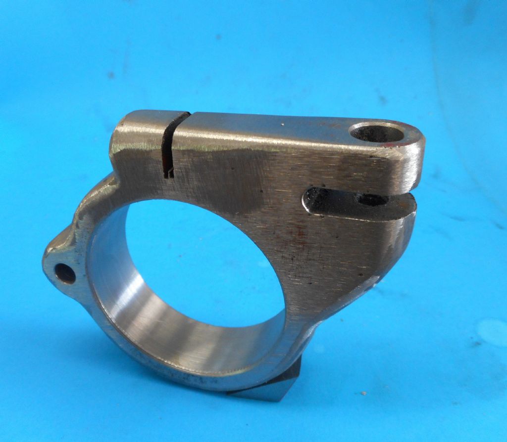
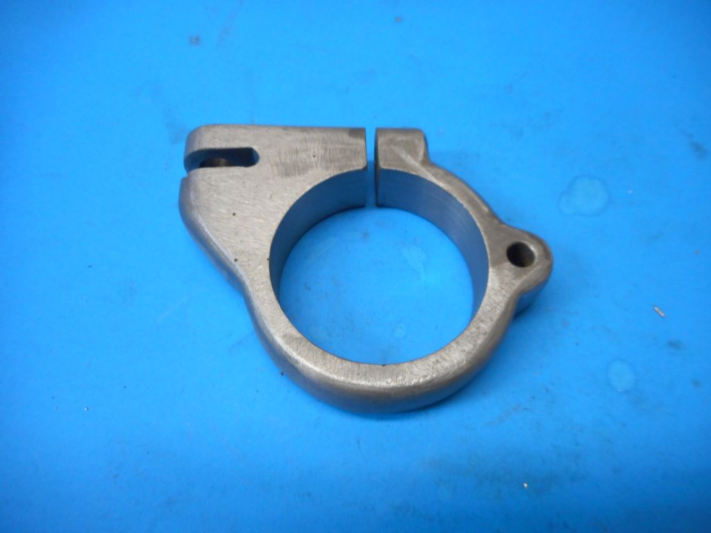
                                                This above is the way it will sit on the tailstock. (After a bit of smoothing down on the belt linisher to reveal the full clamp lurking in there. ) The lug at the top right with the slot will hold the flat link going to the handle. The slot at the very top will be continued all the way through and a pinch bolt placed in the already drilled and tapped hole at the top left on that step there. The big 'ole in the middle goes around the Myford tailstock body of course. Small hole at the left is for an adjustable depth stop for reptition work. (Note to self: Fit a cut-down digital vernier here as a DRO?)

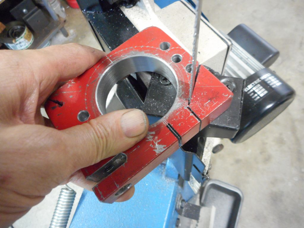
                                                So here's a tip I learned and thought I should share. It's for cutting all those oddball straight lines around the perimeter to make the circle (roughly) where you have to start the cut on a sloping surface and the blade wants to skate sideways and carry on like a secondhand lawnmower.

                                                First, mark up your straight line. Then make a notch on the side of the material where the cut is to start. Do it by hand in the vertical saw position like so:

                                                dscn0093.jpg

                                                When the blade is running though, keep your thumb well out of line with the teeth of death, not ready to jump straight in if you slip as in this posed pic with the blade stopped! Digits are far too handy to go lopping them off. Owww. Didn't mean that one, honest. Sorry.

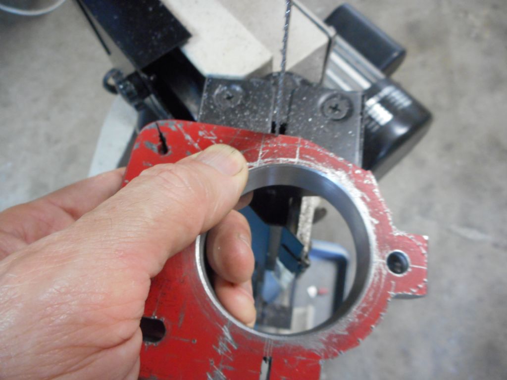
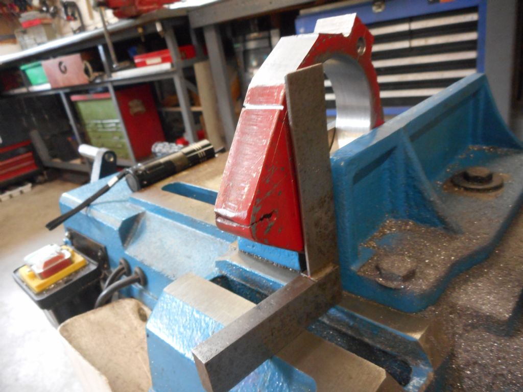
                                                Then set the job in the bandsaw with the scribed straight line in line with the blade. I have just happen to have a try square that lines up with exactly where the blade goes, so I can get the line dead vertical.

                                                dscn0094.jpg

                                                The notch is right there at the top of the square.

                                                dscn0095.jpg

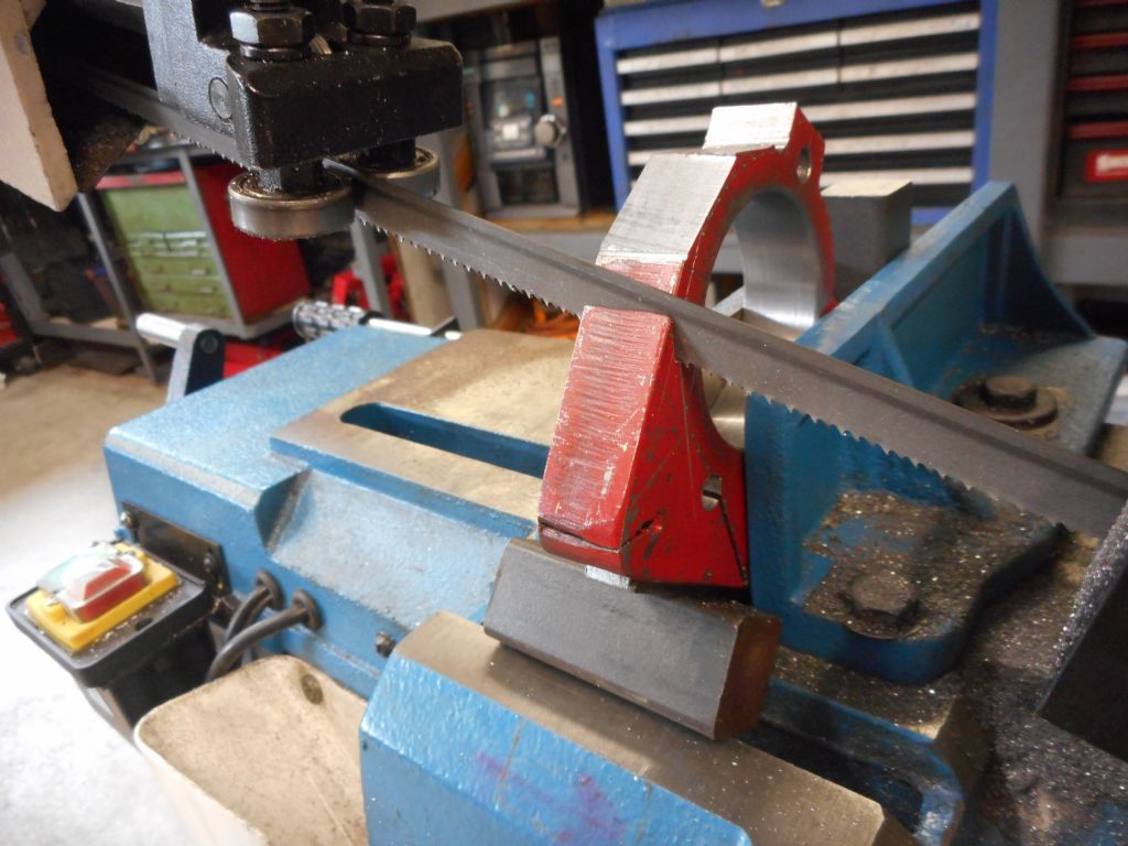
                                                So then you gently George gently lower the moving blade down to kiss the notch that is right in the right place. It stops the blade sliding sideways on that steeply sloping surface. Sometimes you have to just feather it a bit lifting the blade up and slowly lowering it again until the blade has cut its own new starting notch on the angled surface. Once the blade is fully in the job, sit back and watch the action. My favourite part — doing nothing.

                                                Note the packing under the job for support to stop it pivoting. These cheep Chinese bandsaws are not really designed for this kind of duty. So the vice is very flimsy and jaws out of square vertically. But a dig around in the scrapbox solves many woes. The sawcut just about split that line all the way along. Close enough for bush work anyway. Very pleased with the end result.

                                                Progress was slowed by rain — 120mm of it in one day earlier this week — and I could not get outside to finish this part on the belt linisher. So I carried on with some more interesting work milling the aluminium quill clamp into shape on the vertical slide on the Myghty Myford.

                                                Edited By Hopper on 19/03/2022 12:24:21

                                                #590601
                                                Hopper
                                                Participant
                                                  @hopper

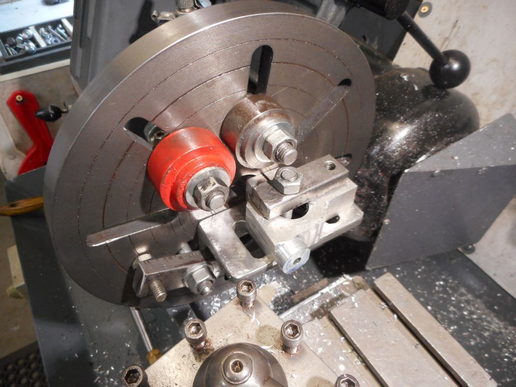
                                                  First I milled the — rather rare – straight bits strait by employing my most deplorable habit of holding milling cutters in a worn out old lathe chuck. I'm told it can't be done but nobody has told the milling cutters yet. None have "wound out" so far in the years I have been pushing my luck with it.

                                                  dscn0097.jpg

                                                  That's my redneck clamping kit made there, made from some flamecut offcuts of steel for the clamps. Drilled and tapped BSW with UNC screws cheekily screwed into them for adjustable packing duties. The main clamping bolts are coach bolts with the heads ground down to fit into Myfraud T slots. They work a treat. But being 3/8" diameter and taking a 5/8" AF spanner, one has to be careful not to overstress the delicate little Myfrod sized T slots. Restraint is required at all times.

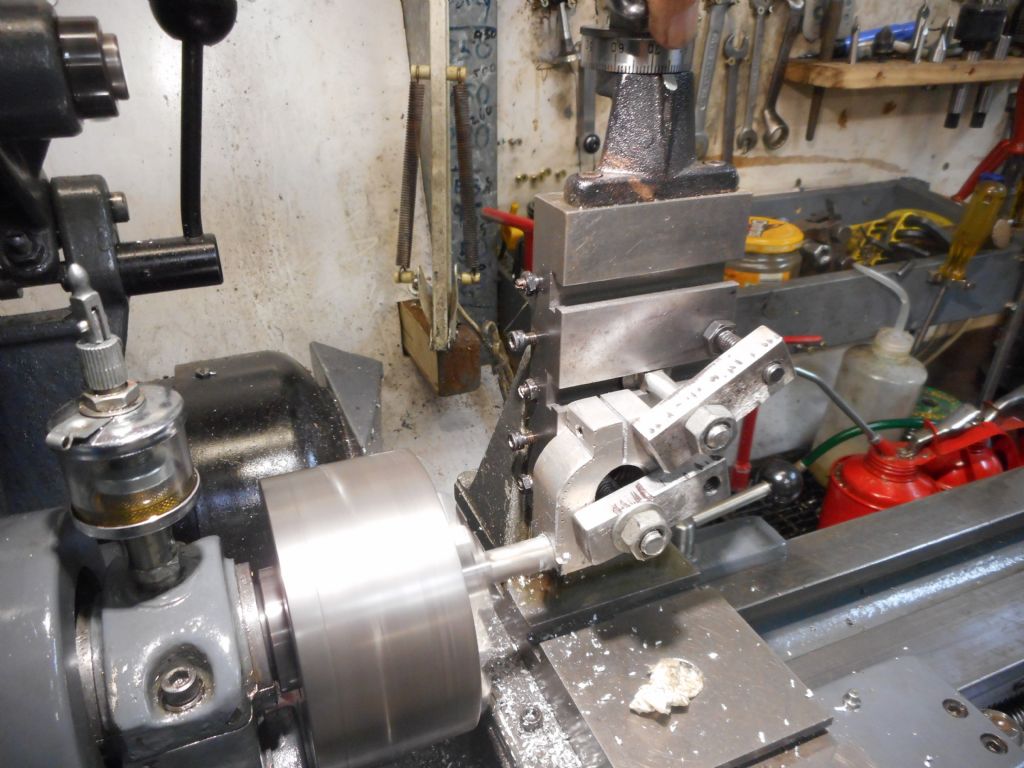
                                                  And then onward through the fog to make one of the square bits round, and to drill and tap a 5/16" UNC thread into it. This is where the other end of the short link will be anchored, the other end going into that slot in the taisltock clamp.

                                                  dscn0103.jpg

                                                  I mounted it on my homemade angle plate, carved from a heavy-walled piece of 4" angle iron cut down to 2". Slots were done by chain drilling and hacksaw and file in the time honoured manner, some years back. Then the angle was milled square by bolting to the cross slide on my old Drummond M Type and running a fly cutter in the chuck. And look at that: I even got busy and scraped both surfaces nice and flat with some bearing blue on a piece of plate glass. Ooh err mister.

                                                  I was a bit worried about that single clamping bolt holding the job still while turning that square bit round, practicing Cuttus Interruptus, so I drilled a centre hole and used a cut down half-centre (dead centre with almost half the tip ground away) to hold it steady while machining. Probably overkill on easy to machine aluminium but hey, all part of the fun.

                                                  So again, this piece was ready for the belt linisher and final finish.

                                                  #590605
                                                  Hopper
                                                  Participant
                                                    @hopper

                                                    So the rain finally stopped. Sun came out and it was about 32C (90F) in the shade. And the linisher is out in the sun since I had to take my shade sail down because of a cyclone. So waited until it rained again and cooled off and stayed cloudy for a while.

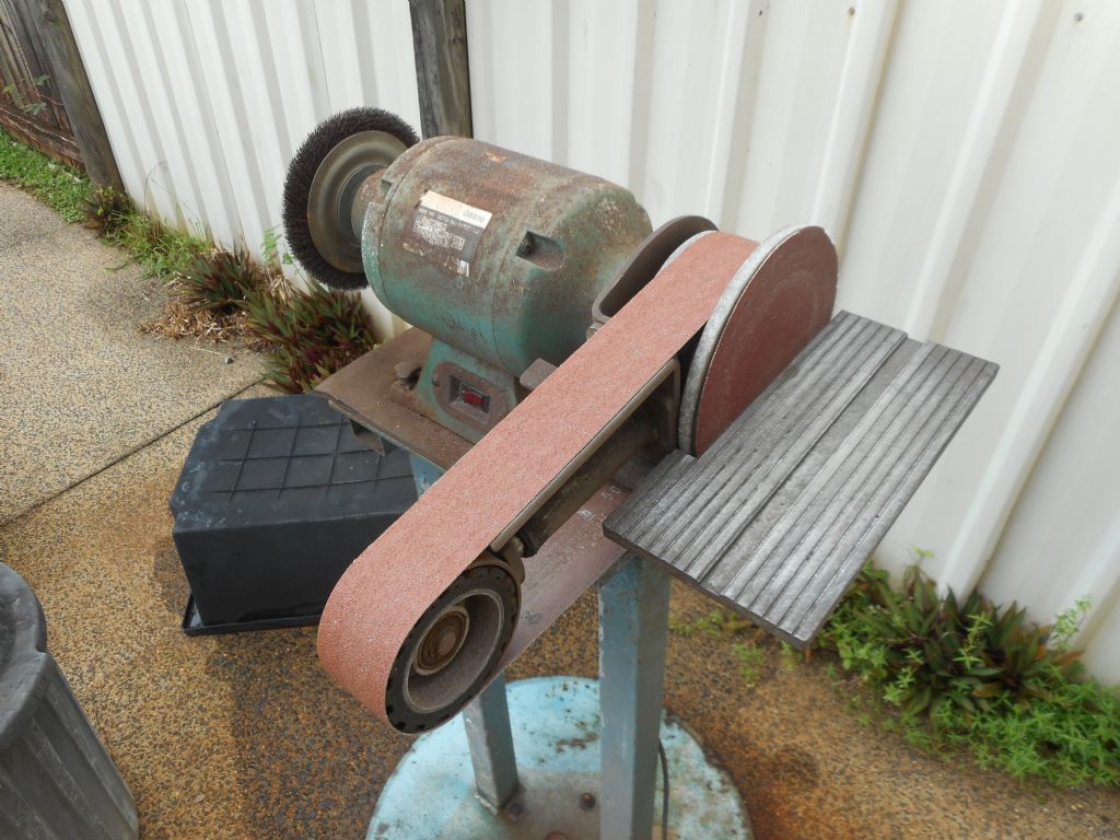
                                                    Here is the finger-grabbin' death machine, the belt linisher. Sold in every Aussie hardware store as the Multi-Tool, it attaches to an 8" pedestal grinder, which has enough grunt that no amount of bone and cartilage will stop it.

                                                    dscn0105.jpg

                                                    Note the stand made from a cut up verandah post welded to an old plough disc. Made by an old farmer I knew. The Multi Tool has a 2" wide belt sander and an 8" diameter flat sanding disc, attached by velcro. As a metal worked used to having my hands safely on the machine dials away from teh cutting action, these woodworkers tools make me very very nervous. One problem is the 3/8 gap between the sanding disc and the table that allows small jobs to get pulled down in there very abruptly, trying to take fingers with them. The "round tuit" list includes bolting a piec of flat ally plate on top to fix this. One day.

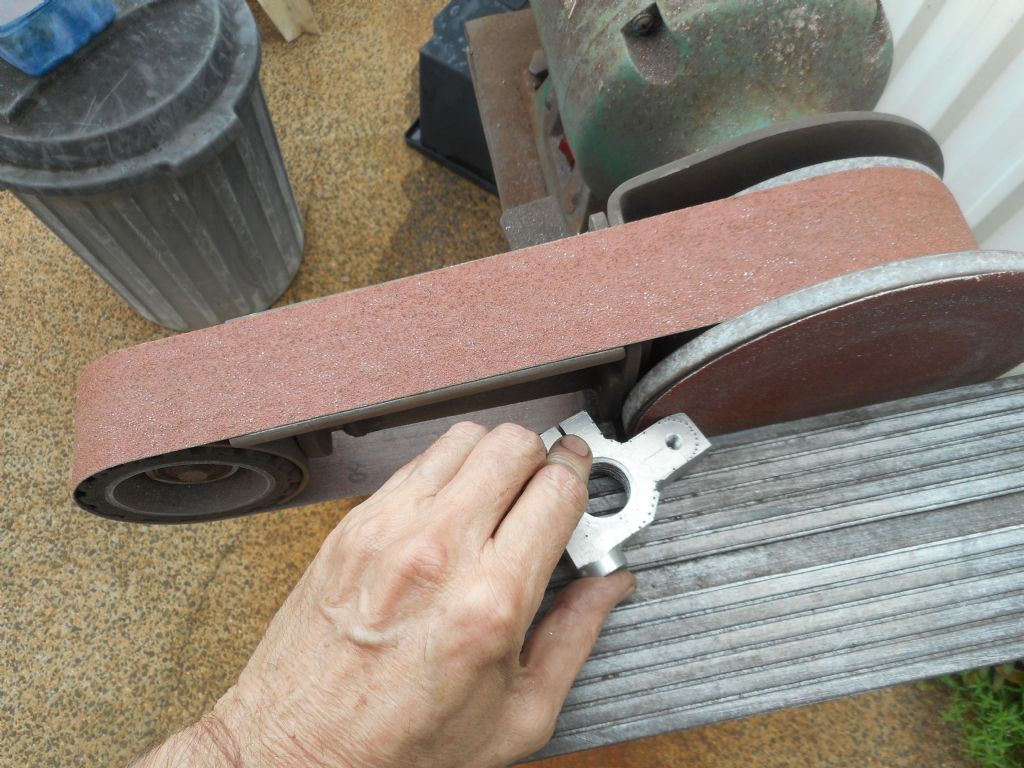
                                                    Of equal concern is look how close to the belt your fingers can be when using the flat disc to shape a job the requires being at the edge like this stationary posed shot. Makes a Drummond lathe with no belt guard look tame.


                                                    dscn0106.jpg


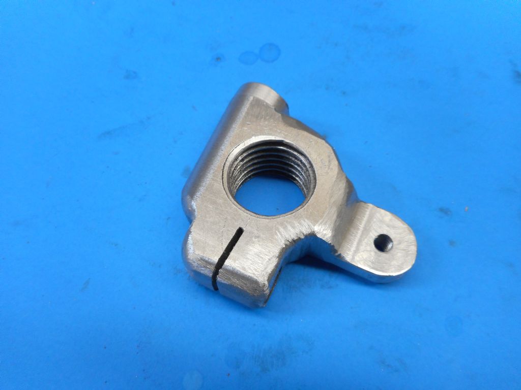
                                                    Anyhow, it did the job and no digits were harmed in the making of this quill clamp. It's starting to look like the real thing now.

                                                    dscn0107.jpg

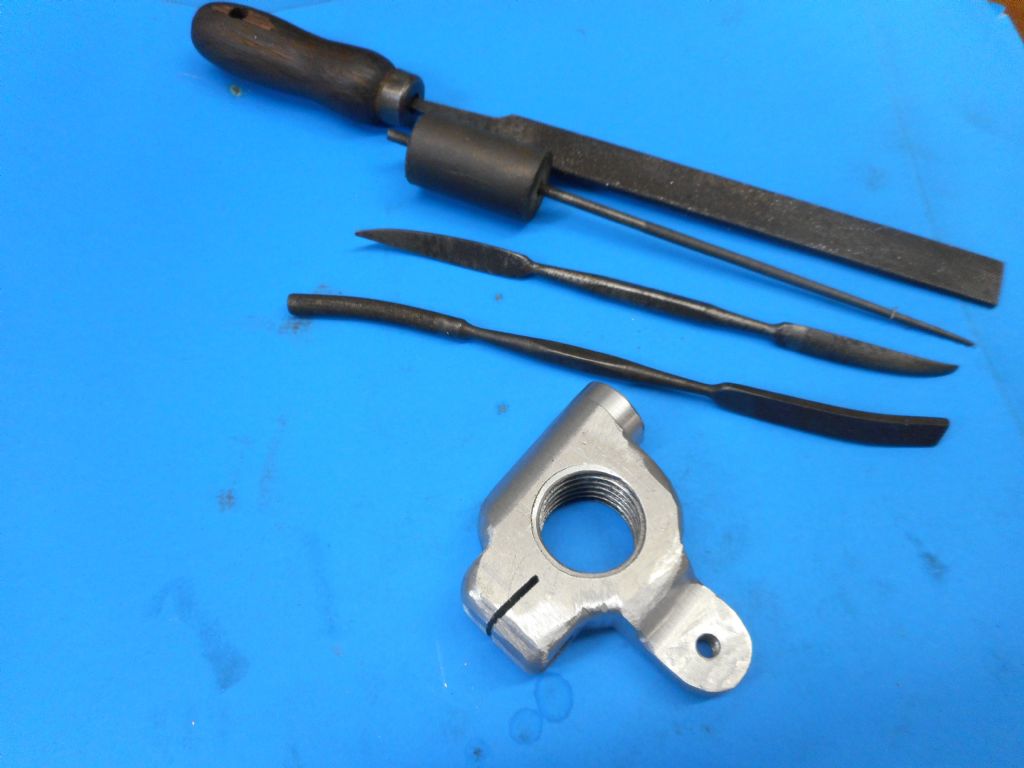
                                                    A bit of finishing off and it will be the real thing. A pair of curved riffler files, a Swiss needle file and flat Warding file await me on the bench next visit to the shed. Then a final smoothing with emery paper and a lick of paint will finish it off. The step that can be seen on the right in this shot was put on with a ball nose cutter in the lathe prior to linishing.

                                                    dscn0109.jpg

                                                    Note wine cork handle on Swiss file. Not world's best practice with the tang sticking right through it. But it was a nice drop of rough red. A shiraz from Kangarilla Road Winery near where I grew up in South Australia. Worth trying if you see it in the bottle-o shop sometime.

                                                    Edited By Hopper on 19/03/2022 13:35:04

                                                    #590892
                                                    Hopper
                                                    Participant
                                                      @hopper

                                                      From this

                                                      dscn0096.jpg

                                                      To this,

                                                      dscn0110b.jpg

                                                      in half an hour on the belt linisher. Magic!

                                                      And another half an hour with riffler files, emery tape, plus used a hacksaw and warding file to finish that slot at the top to allow the pinch bolt to actually pinch.

                                                      dscn0113.jpg

                                                      Edited By Hopper on 21/03/2022 11:04:59

                                                    Viewing 25 posts - 26 through 50 (of 148 total)
                                                    • Please log in to reply to this topic. Registering is free and easy using the links on the menu at the top of this page.

                                                    Advert

                                                    Latest Replies

                                                    Home Forums Manual machine tools Topics

                                                    Viewing 25 topics - 1 through 25 (of 25 total)
                                                    Viewing 25 topics - 1 through 25 (of 25 total)

                                                    View full reply list.

                                                    Advert

                                                    Newsletter Sign-up