Reproduced – my posting here from 2018:-
The subject has been aired several times on here. After I made the simple version with vertical cutter, its shortcomings were soon evident. The main irritant being accurate measurement when advancing the tool tip. I then made one to the Geo. Thomas design and had no further problems.
(There were several postings on here in early November 2018 about b-c boring bars)
There are 2 sources of his design:-
1. GHT's original article in Model Engineer. Model Engineer, 3rd June 1977 p. 615 (Vol 143, No. 3562)
2. That most valuable compendium of GHT's articles – "The Model Engineers Workshop Manual (vol 1)" 1992. Pub: Tee Publishing, ISBN 1-85761-000-8. It's on page 92.
His comment about the normal, 90 deg tool resulting in flexure of a boring bar was well made IMHO. By putting the tool in the bar at an angle, that effect is very much reduced as well as resulting in very much easier ability to measure the swing with a micrometer. Geo. Thomas wrote “….the boring bar in its usual form leaves a lot to be desired. My main objection to it is the absence of any controlled means of advancing the cutter and all my design attempts to provide a suitable means ended in severe weakening of the bar at the point of maximum bending moment.”
IMHO it would time well spent to make one to the GHT design at the maximum diameter commensurate with your cylinder bores.
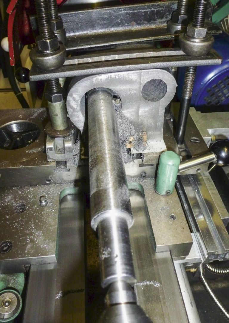
This was my GHT b-c bar boring out a 5" CI cylinder casting.

That brass item on the casting, under the boring bar, contains several small Neodymium magnets. It should have been within a plastic bag so that the collected iron bits could have been emptied straight in the bin !
David Jenner.


