My new lathe a Warco 918

Advert

My new lathe a Warco 918

Home Forums Workshop Tools and Tooling My new lathe a Warco 918

Viewing 25 posts - 126 through 150 (of 197 total)
  • Author
    Posts
  • #475607
    Ron Laden
    Participant
      @ronladen17547

      Hi Martin

      Thanks for doing that test, appreciated. The swarf issue did cross my mind but I wouldn't be using the Jaws. wink

      Ron

      Advert
      #475840
      Ron Laden
      Participant
        @ronladen17547

        I took a gamble and bought a cheap £8 .surprise digital caliper for a little project I am going to try on the lathe.

        I expected it to be rough and it is but a couple of hours stripping it down and improving where I could and its now much better than it was. I need it to be reasonably accurate but not perfect and a few comparison tests against my Mitutoyo and it is within 1 to 2 thou along the full range of 6 inches so thats fine for how I hope to use it.

        Just to give some idea of how rough it was,the top and bottom running faces of the beam looked as if they had been finished on a bandsaw but at £8 what can you expect. I used a very fine file and draw filed the faces finishing with 800 and 1200 paper, after readjusting the head it is quite smooth, very smooth actually considering.

        I made the mods and waiting for some magnets plus I need to make a mounting block and a couple of other bits, I am sure you can guess what I,m up to, it may work out it may not but hardly a drama if it doesnt at £8.

        img_20200529_092829.jpg

        Edited By Ron Laden on 29/05/2020 11:10:43

        #475845
        not done it yet
        Participant
          @notdoneityet

          Did you add those countersunk holes? That might help us guess.🙂

          Edited By not done it yet on 29/05/2020 11:24:45

          #475846
          Ron Laden
          Participant
            @ronladen17547

            Yes I added the csk holes.

            #476311
            Ron Laden
            Participant
              @ronladen17547

              Made and fitted the mount to the caliper.

              p.s. Pan head screws as I don't have any csk at the moment. 

              img_20200531_101608.jpg

              Edited By Ron Laden on 31/05/2020 10:38:35

              #476313
              Ron Laden
              Participant
                @ronladen17547

                Sorry should have said if it works out it is going to be a poor man's DRO for the carriage, I say poor man's as there is only £8 in it so far.. smiley

                #476318
                BOB BLACKSHAW 1
                Participant
                  @bobblackshaw1

                  Looking with interest Ron as I to have a 9×20 but Im using a clock for mine. I tried to drill and hacksaw a Aldi calliper a few years ago but it was so hard that the drills would not touch it and similar with the hacksaw .

                  Bob

                  #476320
                  Ron Laden
                  Participant
                    @ronladen17547

                    Hi Bob, well that speaks well for Aldi calipers as this cheapie I have which is said to be stl stl/hardened is the strangest stl I have come across. It cuts and machines so easily I can hardly believe it is stl. However it is non magnetic but I, m guessing it is some Chinacheeseium concoction, the non magnetic is a bonus though for the way I am going to mount it.

                    Will post more when I,m a bit further on.

                    Ron

                    Edited By Ron Laden on 31/05/2020 11:01:35

                    #476323
                    Howard Lewis
                    Participant
                      @howardlewis46836

                      Nice looking job, Ron!

                      A long time ago, I tried drilling an LIDL digital calliper. After regrinding the drill three times for the first hole, I gave up!

                      A proper DRO now lives on the Tailstock!

                      Howard

                      #476352
                      Ron Laden
                      Participant
                        @ronladen17547

                        Hi Howard,

                        Yes I am sure any half decent caliper would be made of better stuff than my cheapie but hopefully it will be ok for my purpose, after all it wont be under any stress not that any caliper should be of course. The good thing is the caliper is reasonably accurate for how I will be using it, measuring and setting lengths of cuts etc, it is within 1 to 2 thou of my Mitutoyo across the full 150 mm.

                        I have been thinking of giving the idea a try for some time so when I saw a digital caliper for £8 I thought I would give it a try, will see how it turns out.

                        Ron

                        #476735
                        Ron Laden
                        Participant
                          @ronladen17547

                          The carriage DRO is just about finished, waiting for some magnets but temporarily fitted it with some smaller ones I had which did in fact hold it well enough. I went down the magnet route as I wont be leaving it on the lathe when not required and I can see it getting damaged if left in situ all the time. The magnets make it easy fit/easy removal it takes just seconds. The swarf guard I have made up is also fitted via magnets so again quick fit.

                          Quite pleased with it considering it cost £8 plus some offcuts and a bit of time.

                          p.s. Click on image to enlarge.

                          dsc07670.jpg

                          Edited By Ron Laden on 01/06/2020 16:59:18

                          #478893
                          Ron Laden
                          Participant
                            @ronladen17547

                            Has anyone heard, read or know of the cross slide been converted to power feed on the 920 lathe, the usual mods to the 920 are well documented but I havnt found any mention of a power feed. I would be surprised if it hasnt been done when you consider the number of 920,s that must be out there, if it has been done I would be interested in their approach.

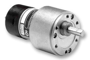
                            I have sketched up how I would tackle it and have been looking at what I think would be suitable geared motors, currently considering the Mclennan range (picture below) 24 volt, 30/1, 110 rpm (24v), 15N/cm, decent quality with all metal gearbox and reasonably priced. The motor is a bit of guess work as I dont know what sort of torque is required so the one I am considering is down to my thinking it would be ok.

                            1784831-40.jpg

                            #478927
                            Niels Abildgaard
                            Participant
                              @nielsabildgaard33719
                              Posted by Ron Laden on 10/06/2020 13:10:13:


                              I have sketched up how I would tackle it and have been looking at what I think would be suitable geared motors, currently considering the Mclennan range (picture below) 24 volt, 30/1, 110 rpm (24v), 15N/cm, decent quality with all metal gearbox and reasonably priced. The motor is a bit of guess work as I dont know what sort of torque is required so the one I am considering is down to my thinking it would be ok.


                              A gentleman in Germany sells small lathe electronic leadscrews for a living and offers stepmotors in the range of 1.5 to 3,3 NewtonMeter for leadscrew and crosslide.Your proposal is probably not to big.


                              Steppers for lathes


                              The real problem is to make sure that feed stops imidiately if lathe spindle stops unexpected.

                              Edited By Niels Abildgaard on 10/06/2020 15:32:37

                              #479108
                              Ron Laden
                              Participant
                                @ronladen17547
                                Posted by Niels Abildgaard on 10/06/2020 15:28:29:

                                Posted by Ron Laden on 10/06/2020 13:10:13:

                                I have sketched up how I would tackle it and have been looking at what I think would be suitable geared motors, currently considering the Mclennan range (picture below) 24 volt, 30/1, 110 rpm (24v), 15N/cm, decent quality with all metal gearbox and reasonably priced. The motor is a bit of guess work as I dont know what sort of torque is required so the one I am considering is down to my thinking it would be ok.

                                The real problem is to make sure that feed stops imidiately if lathe spindle stops unexpected.

                                Edited By Niels Abildgaard on 10/06/2020 15:32:37

                                Thats a good point Niels, though I dont quite know how I would achieve that with the drive been independent of the lathe.

                                The other thing I will need is a method of engaging/disengaging the drive from the cross slide lead screw. I am thinking of a small dog clutch though I have no experience of designing/making one so I will have to get the thinking cap on, it doesnt need to be anything complicated.

                                Ron .

                                #479295
                                Ron Laden
                                Participant
                                  @ronladen17547

                                  I removed the cross slide to size things up and found a couple of surprises, the first is the saddle and cross slide running faces have at some point been scraped so that was a nice find. The second was that it will be quite easy to modify the saddle to accept the drive shaft, just need to put the saddle up on the mill and cut a channel out through the rear. A spigot turned on the end of the lead screw to connect to the drive and that should be about it, the rest of the drive assy will be fixed to the rear of the saddle.

                                  There is just enough space to mill a couple of pockets for a front and rear microswitch which could be worth doing to prevent any overrun of the drive.

                                  img_20200612_111336.jpg

                                  #479469
                                  Mike Woods 1
                                  Participant
                                    @mikewoods1

                                    That is a nice leadscrew nut, much better looking than the original design on my Chester 920. I think this must be one of the many improvements made by the previous owner. I asume that you will be removing the leadscrew to make modifications for the motor drive. If you do, would you be willing to post a picture showing the nut? I would be interested to see how backlash adjustment is done.

                                    #479480
                                    Ron Laden
                                    Participant
                                      @ronladen17547

                                      Here you go Mike a picture of the modified lead screw drive assy. You can see that the nut is steel with a full length brass insert, of course I didn't see the original parts but going by the manual drawing the new nut looks to be longer.

                                      The lead screw runs in a pair of sealed ballraces, to the right of the bearing housing there is a threaded nut with a grub screw the nut adjusts out any end float.

                                      The cross slide gib has been replaced with a heavier brass version 5mm thick and the adjusting screws increased from 3 to 9. I must admit I thought the 9 screws over the top but who am I to argue there is no play at all and it is silky smooth in operation. The top slide has the same mods, scraped in faces, ball races, heavy brass gib and 6 adjusters, he certainly went to town on it when he made the changes.

                                      img_20200613_045514.jpg

                                      #479548
                                      Ron Laden
                                      Participant
                                        @ronladen17547

                                        Made a start just cut the channel through to the rear of the saddle. The last cut revealed a porous area but there doesn't seem to be any weakness or depth to it plus there is an inch of metal below it.

                                        img_20200613_100200.jpg

                                        #479563
                                        Mike Woods 1
                                        Participant
                                          @mikewoods1

                                          Thanks for the photo Ron. Crikey, with my night owl question and your up with the larks response, you must be a very early riser, or located several beneficial time zones away.

                                          The modification looks to be very well done indeed. Your description of the nut answers the question on backlash adjustment for wear. My original thought was that the brass insert might have been two pieces, one fixed in place the other threaded into the nut body and locked after adjustment. It was difficult to see from your original picture.

                                          Yes, having nine gib adjusting screws does seem to be a bit of overkill and patience tester when setting up, but if it works, that's what counts.

                                          I did come across a post on another forum on the subject of power feed conversion, but it was more a discussion of motor types. However, a video at the very end show how a 10×22 size lathe was modified to add a drive shaft below the lead screw and combined with a redesigned apron to make a geared system. Ingenious, but complicated. Your approach seems much simpler to make and with suitable electrical fail safes, probably more flexible in use. Looking forward to your updates (one of which has already appeared).

                                          For general interest, here is a link to the discussion thread.

                                          https://www.homemodelenginemachinist.com/threads/power-crossfeed-help.22091/

                                          Mike

                                          #479609
                                          Ron Laden
                                          Participant
                                            @ronladen17547

                                            Hi Mike, I should pay more attention to the parts, the nut does indeed have two brass inserts you can see in the picture below the pair of tiny grubs screws for adjustment at either end.

                                            Ron

                                            img_20200613_140404.jpg

                                            #479659
                                            Mike Woods 1
                                            Participant
                                              @mikewoods1

                                              Once again, thanks for the follow up Ron.

                                              #479728
                                              Ron Laden
                                              Participant
                                                @ronladen17547

                                                Turned up and tried for size the first part of the drive leaving enough material on the rear which will become the first half of the clutch. Still working on that, I have a couple of ideas trying to keep it simple but effective.

                                                img_20200614_074801.jpg

                                                #480264
                                                Ron Laden
                                                Participant
                                                  @ronladen17547

                                                  A couple of pictures of my take on a dog clutch for the cross slide feed, the slotted traveller is spring loaded with an internal compression spring keeping it pushed back and disengaged against the lever boss. To engage the clutch the lever boss is slid forward pushing the traveller to engage both pins for drive. I will have a stepped or angled slot on the motor mount for the lever to engage in maintaining the connection of the two pins.

                                                  img_20200616_133817.jpg

                                                  I used the end of the top slide to keep the sprung traveller engaged, the lever will be held in a slot on the actual fitting to the lathe.

                                                  img_20200616_133914.jpg

                                                  #480388
                                                  Ron Laden
                                                  Participant
                                                    @ronladen17547

                                                    Forgot to add the pic of the parts that make up the clutch.

                                                    img_20200617_054513.jpg

                                                    #481649
                                                    Ron Laden
                                                    Participant
                                                      @ronladen17547

                                                      I now have a driven cross slide which has worked out quite well, tested it this morning with various cuts, various materials. With brass and aluminium it sailed through it with no issues but of course steel would be more of a test. I put up some 25mm EN1A and tried various facing cuts, I went up to 1.00 mm which was fine and it would probably handle more but I didnt push it. The thing I was hoping the drive would handle is parting so using the rear tool post and a 2.0 mm insert I tried the steel. No issues at all, no grabs, no hesitation, cut smoothly all the way through, how nice it was to have both hands free whilst parting off.

                                                      I then tried parting some EN8 and the drive wasnt so happy with that, it hesitated a couple of times. I think the answer is to upgrade the motor/box to one with a higher torque rating. I happen to have one, its a bit bigger in diameter, twice as long but with 4X the torque of the one I am using and wont need that much work to change it over.

                                                      The way I have gone about fitting the drive means the motor/box/clutch and drive hanging out the back off the saddle. To use an inline motor on the centre line of the lead screw it has to be positioned that way as the cross slide runs out 90mm when fully rearward. It would be possible to have the motor closer and tucked underneath the cross slide but it would mean building a gearbox of some sort.

                                                      Anyway pleased with the drive it works well enough, just a couple of improvements to do, change the motor and sort the electrics plus build a small control unit and fit to the front of the lathe.

                                                      img_20200623_064146.jpg

                                                    Viewing 25 posts - 126 through 150 (of 197 total)
                                                    • Please log in to reply to this topic. Registering is free and easy using the links on the menu at the top of this page.

                                                    Advert

                                                    Latest Replies

                                                    Viewing 25 topics - 1 through 25 (of 25 total)
                                                    Viewing 25 topics - 1 through 25 (of 25 total)

                                                    View full reply list.

                                                    Advert

                                                    Newsletter Sign-up