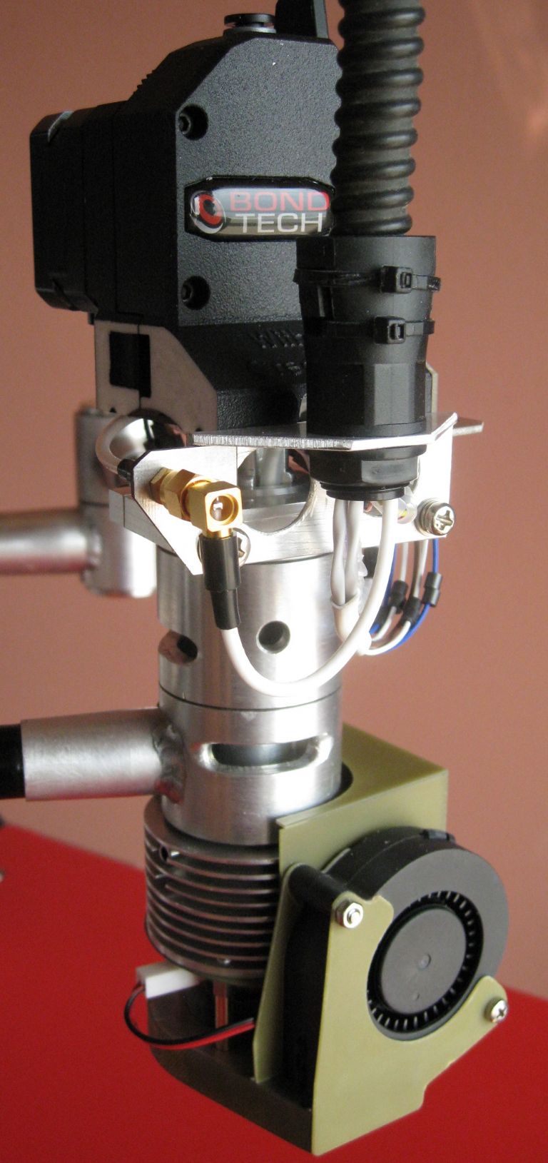
My Morgan SCARA coming together

Advert

My Morgan SCARA coming together

Home Forums 3D Printers and 3D Printing My Morgan SCARA coming together

Viewing 18 posts - 1 through 18 (of 18 total)
  • Author
    Posts
  • #31646
    Joseph Noci 1
    Participant
      @josephnoci1
      Advert
      #480682
      Joseph Noci 1
      Participant
        @josephnoci1

        WARNING – Those opposed to over-engineering should avoid reading this lot…

        This project started as a challenge, rather than any need for a 3D printer. It has been almost a year and slowly it is starting to come alive – although I still find no need for a 3D printer…

        Anyway, a challenge it is – Polar co-ordinate world to work in, with inverse kinematics and some fun math..And I don't leave it there – the Hot end is an induction heated one, the heat part is currently being worked on on the bench in an attempt to see how often I can blow it up in one day…

        Also, the extruder drive train will ( hopefully..) be a brushless (RC) motor drive – so am also developing a Step/Direction input brushless motor servo drive. The reason for the induction heater and brushless motor drive is to try get the entire hot end / extruder below 150grams, 200grams max. I also want the extruder to be at the hot end, no Bowden tube, etc. So a lot of fun still to be had.

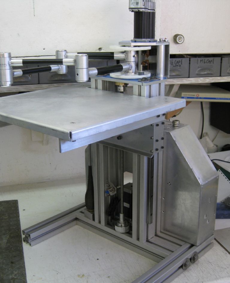
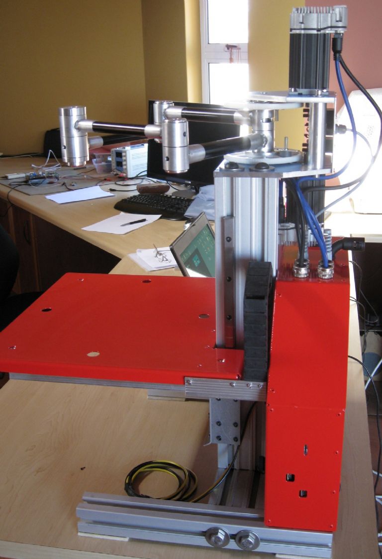
        In the meantime, the actual SCARA arms, the drive servos/stepper, powers supplies, Nucleo brain, etc ias all together, and my good Wife is software-ing it – I have to fit a spring loaded pen to the hot-end end, so she can draw some calibration verification squares and circles to start.

        Some photos – beware, the qty of pics matches the engineering effort..

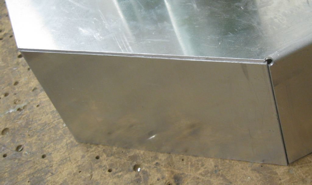
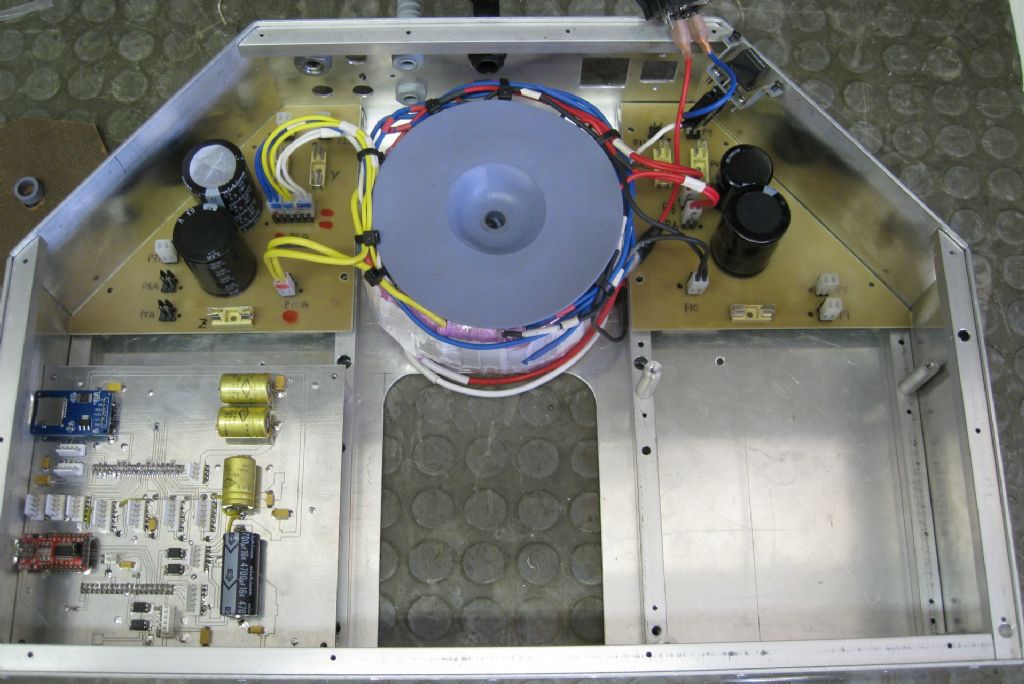
        The electrical/electronics box, ready for tig welding

        ready to tig elec box.jpg

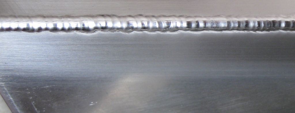
        Some tigging done..

        box tigged.jpg

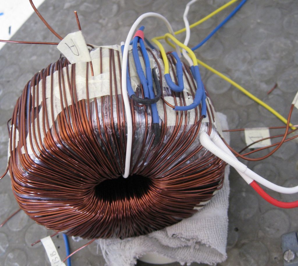
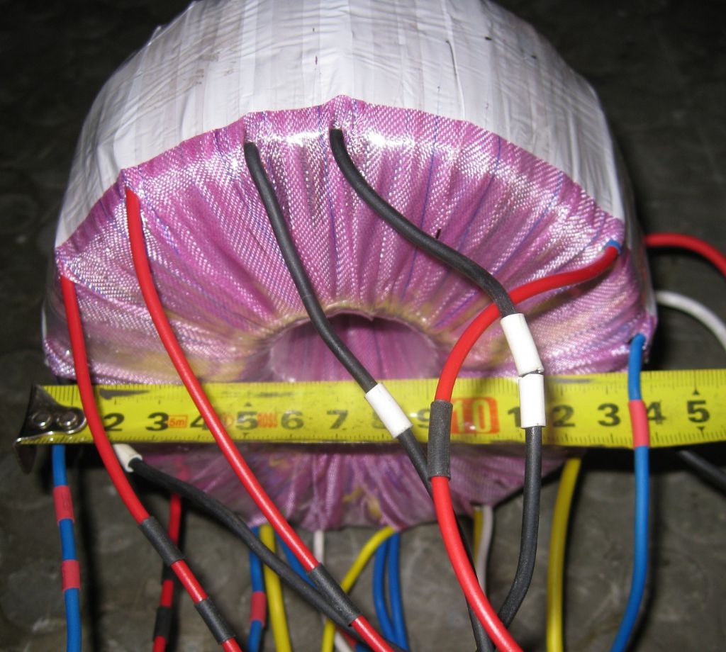
        Re-winding an old Amplifiers toroidal txfmr to suit my voltage needs:

        winding transformer.jpg

        All Wound:

        wound transformer.jpg

        Trial wiring before stripping and painting:

        start of trial wiring.jpg

        Ready to strip and paint:

        ready to paint.jpg

        Painted:

        painted.jpg

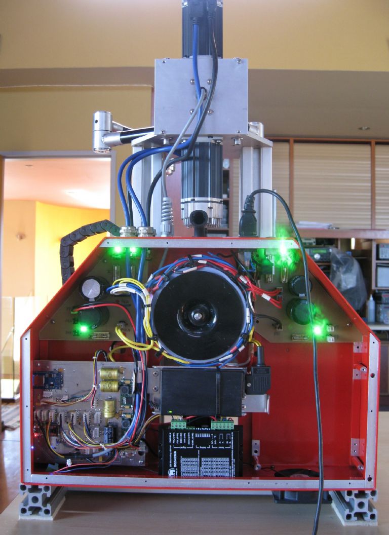
        Starting to test things:

        test starts.jpg

        Electrical box wired – Extruder control and induction heater still to go in at lower right.

        electrical box.jpg

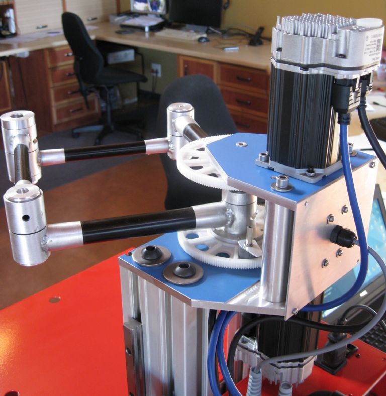
        SCARA Arms servos:

        servo drives.jpg

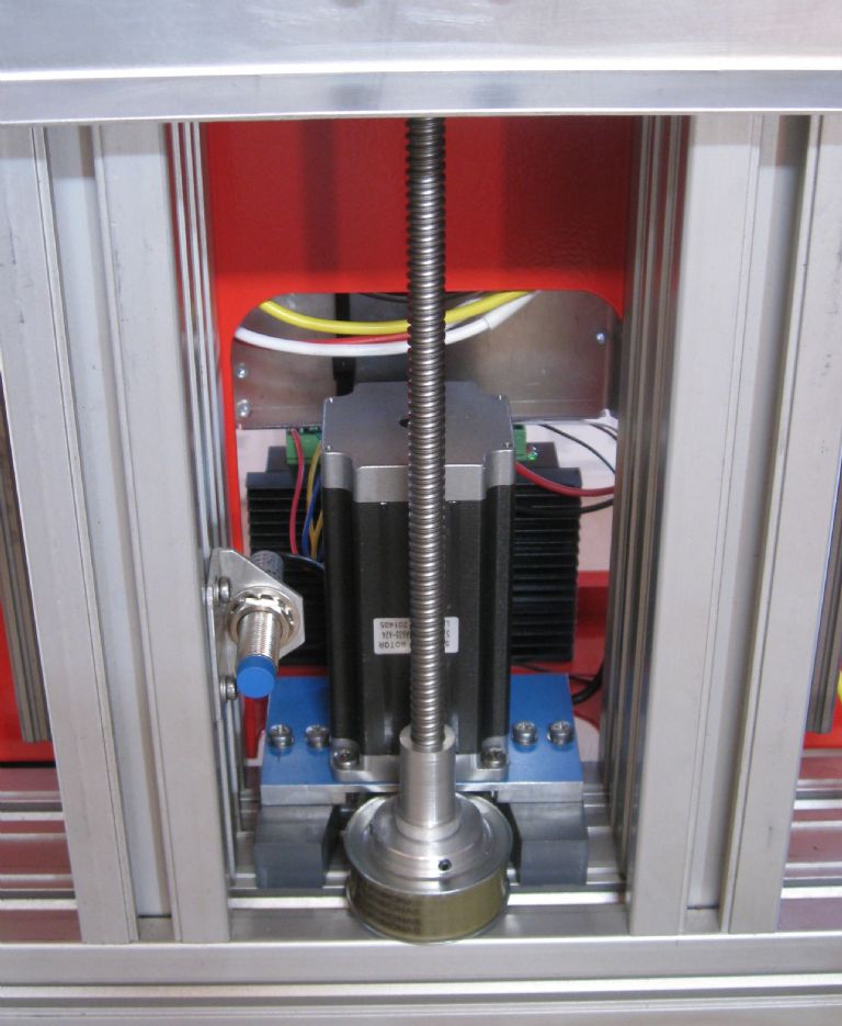
        Z Axis Stepper drive and leadscrew:

        z stepper drive.jpg

        Next installment when the thing moves about and draws stuff…

        Joe

        #480700
        Grindstone Cowboy
        Participant
          @grindstonecowboy

          That's very impressive, Joe, well done yes

          Rob

          #480753
          Ady1
          Participant
            @ady1

            I'm going to have to look this one up….

            piccies

            description

            looks lovely btw

            #480756
            Neil Wyatt
            Moderator
              @neilwyatt

              Very lovely Joe, but yes just a tad over-engineered, maybe

              Even my string and rubber bands machine seems to have the accuracy determined by the ooziness of the filament rather than the precision of the mechanicals.

              I'd be considering what other uses you could make of that mechanism – laser cutting, engraving, even SLS?

              Neil

              #480764
              Joseph Noci 1
              Participant
                @josephnoci1

                Neil, a 'tad' is slightly understating, no?..

                I am keen to be able to fit a laser head of sorts, but that is another field on its own. A fibre laser would be nice as the weight is remote, with only the fiber and lens at the end of the arms, but the fibre laser is rather limited in application with certain materials – wood and many plastics are a no go, pvc, acrylic, etc. I did try one of those chinese '5 watt' blue laser heads – absolute junk – if that was 200mW it was a lot…and the control electronics was useless – pulse control was very poor so raster engraving was mediocre. There are a lot of those type lasers from Ebay, Ali-xyz, etc, but the specs are impossible to believe..

                So, any ideas for a good (light weight) engraving laser are welcome!

                No idea what sort of laser is needed for SLS, but the idea is interesting – when the machine is sort of working I may try the SLS route.

                Thanks for the good words chaps!

                Joe

                #480766
                Enough!
                Participant
                  @enough
                  Posted by Joseph Noci 1 on 18/06/2020 12:10:49:

                  WARNING – Those opposed to over-engineering should avoid reading this lot…

                  On the contrary, Joseph. Given how poorly many of the lower-priced commercial 3D printers are "engineered", over-engineering is refreshing.

                  Nice job!

                  #486380
                  Joseph Noci 1
                  Participant
                    @josephnoci1

                    Please excuse if I am repeating old queries – I did try a search on the site and did not find much…

                    What Slicers are in 'popular' use by people on this forum? The firmware for my oddball SCARA printer is slowly coming to life – it can draw squares and circles to decent accuracy, all done by the firmware interpreting G_code.

                    Next step is to investigate what sort of G_code flavours are generated by the Slicer package, to ensure my firmware interprets it all. I have investigated Cura and Slic3r – Cura is sort of 'open' and free, but seems a few years ago it became an Ultimaker product, focused on the Ultimaker printers. Anyone using Cura?

                    Slic3R seems more appropriate for my use – reasonably simple for a beginner!

                    There are so many settings and controls in the slicers – hotend and hotbed fan speed controls – anyone here actually use those features?

                    Maybe Neil will chip in – Neil does do some 'real' stuff on his printer!

                    Joe

                    #486391
                    Andrew Entwistle
                    Participant
                      @andrewentwistle

                      Hi Joe,

                      I have found little difference between the performance of Cura, Slic3r and Simplify3D slicers, with the exception that Simplify3D supports are easily customisable and they detach cleanly, without the need for tools. If I made my living 3D printing then the time saved in cleaning up prints with supports would easily pay for Simplify3D, but otherwise it is hard to justify the premium.

                      I have found it useful to be able to raise the bed temperature for the early layers with PLA for adhesion, then drop it later. Also turning the part cooling fan on after a few layers prevents fine parts from melting, but ensures adhesion to the bed. 

                      Andrew.

                      Edited By Andrew Entwistle on 18/07/2020 09:33:57

                      #486392
                      SillyOldDuffer
                      Moderator
                        @sillyoldduffer

                        Posted by Joseph Noci 1 on 18/07/2020 07:37:12:…

                        I have investigated Cura and Slic3r – Cura is sort of 'open' and free, but seems a few years ago it became an Ultimaker product, focused on the Ultimaker printers. Anyone using Cura?

                        Slic3R seems more appropriate for my use – reasonably simple for a beginner!

                        Joe

                        Another impressive project!

                        I went through the Cura vs Slic2r debate too, and decided on Cura because it's 'reasonably simple for a beginner'!

                        I've not done enough 3D printing to say more than Cura just works for me so far. Slicing proved to be the easiest stage in the production process. No problem installing the software, recognising the printer, loading a file, setting options, or printing. (Windows and Linux)

                        Both packages are Open Source and both do basic printing. Comparing feature lists there's a feeling each addresses the shortcomings of the other in advanced territory. For example Cura requires supports to be added manually, while Slic3r adds them automatically. The issue is Slic3r doesn't allow unwanted supports to be removed, which might be a nuisance As I've not printed anything needing supports yet, I can't say which approach makes most sense, though I suspect it probably depends on the job.

                        My guess is you could start with either software and swap later without bother. It's not like choosing a complicated CAD package where learning to use it is a major investment.

                        Health warning: I've not tried printing anything complicated yet. Could be Cura will let me down with a thump next time I use it!

                        Dave

                        #486410
                        Joseph Noci 1
                        Participant
                          @josephnoci1

                          Thanks for the info. I guess the issue is , as usual, that when starting in the game one does not know what one does not know…So everything seems to loom and be a little overwhelming.

                          Since my mechanics are a little different, I am assuming its not as simple as choosing one on the pre-defined of even custom print setups in the Slicer software. Growing on the overwhelming tone, it therefore seems daunting to try discover what sort of G-Code is 'typical' for 'a' printer. And which codes do these packages use to do some of the more esoteric things – control of fans, heaters, etc. Do they use the codes normally used to turn on coolant, etc?

                          When printing circles or arcs, do they break it up into many small linear segments, or do they use G17/G2 with I and J parameters? Do they use circular interpolation as well ( G2/3)? How does the software allow position of the print on the table – does it use G91 for co-ord system offsets? G54-59 for work offsets?

                          Since it is probably not a good idea when printing with sharp angles, eg, a square, to stop at the corner before moving in the next direction, the is probably some sort of 'constant velocity' mode implemented. Is this conventional, ie G61/G64 ??

                          Etc, etc….So at the moment it is very much trial and error – using some simple STL's – a square, a star, a circle, etc, and trying to slice them in Cura and Slic3r and see what they generate – each package also has dozens of 'parameters' that can be set up for other things – fan cooling, etc ( and Cura generates a different code for fan speed to what Slic3r does !!!) – but what a mission…

                          There must be some sort of basis on which most printer mnfrs established their definition files for that specific printer, but no such definition to be found – have spent far to much time digging through the mounds of open source printer firmwares – Marlin, Smoothieware, etc….

                          Ah well, tis the path I chose..

                          Joe

                          edit : change there to their…as usual..


                          Edited By Joseph Noci 1 on 18/07/2020 11:04:18

                          #486417
                          matt
                          Participant
                            @matt27093

                            Hi Joseph

                            Interesting project. David Crocker, designer of the duet control boards played around with a scara printer on blog a couple of years ago. There may be some useful info on their for you. Search for DC42 blog.

                            following link list common g and m codes used on 3d printers, may be useful as a starting point.

                            3d printer g and m codes

                            #486440
                            Joseph Noci 1
                            Participant
                              @josephnoci1

                              I have found some useful links on the internet at last.. Take a lot of time digging around for pertinent info!

                              A very good Wiki that lists all the commands and describes each in useful detail, and also gives a table breakdown indicating which printer firmware uses which codes and modes.

                              Using that info, and playing with the slicer using a simple STL file, I am managing to obtain a G-Code file that makes sense and is understandable.

                              Some progress!

                              Matt, thanks also for that reference – equally useful!

                              G_code list for some 3D printers

                              Joe


                              Edited By Joseph Noci 1 on 18/07/2020 14:12:33

                              #486497
                              Howard Lewis
                              Participant
                                @howardlewis46836

                                Good work Joseph!

                                If it is big, solid and rigid, it will last and be accurate.

                                Better to be overengineered than the reverse. That way lies frustration, inaccuracy and waste.

                                Better a brick mausoleum that a tent with no guy ropes.

                                I stand in awe

                                Howard

                                #486500
                                Joseph Noci 1
                                Participant
                                  @josephnoci1

                                  Thank you Howard! But may i suggest you rather sit – this could take a (long) while!

                                  Joe

                                  #487140
                                  Joseph Noci 1
                                  Participant
                                    @josephnoci1

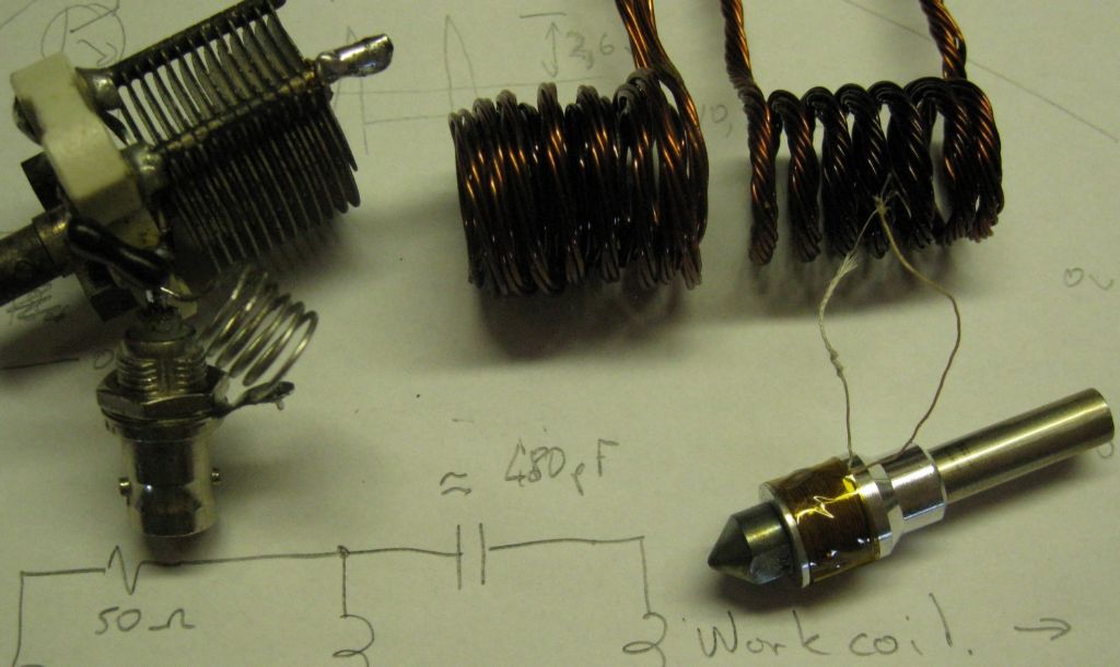
                                    I have progressed a little on the Induction Heater for the printer Hot End. I tried various options, Class D switcher, Royeur, and a few others. The Royeur worked well, is simple, and was quite efficient, but failed as all these topologies did, because they are all 'low frequency' – that is, typically below 500Khz, and mostly around 80 to 200KHz. I am trying to heat an aluminium shaft, which holds the hot end nozzle ( non-magnetic stainless steel) and for that the frequency needs to go up – way up – to the 7 to 14MHz region.

                                    So to test this theory , before starting on the RF source design, etc, I dragged out of the store room an old 50watt solid state CW transmit brick ( was used as a variable power output HF CW beacon, for NVIS tests, long, long ago..). I knocked up a test hotend, with the nozzle attached and a 6mm thin wall St/Steel tube as intended heat break.

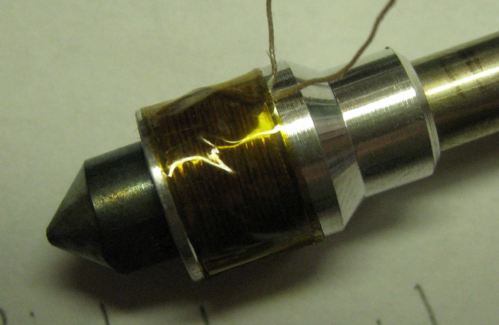
                                    The body is aluminium, with the heating coil of 16turns, diameter 10.5mm. This measured out at 3.5+j20 ohms.

                                    The RF source was set to around 35 watts, and a 50ohm matching network kludged to match to the work coil.

                                    The results were indeed very pleasing!

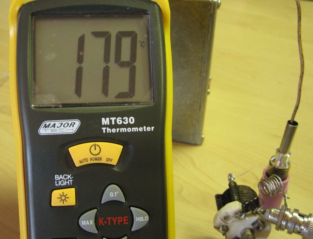
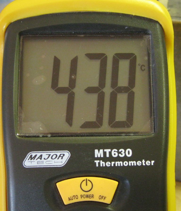
                                    The hotend heats from 25degC ambient to 180deg in 15sec, to 295deg in 20sec and to 440degC in 50sec.

                                    Some non-linearity there, mainly due to the heated material eddy currents behaving differently at the climbing temps.

                                    Some pics :

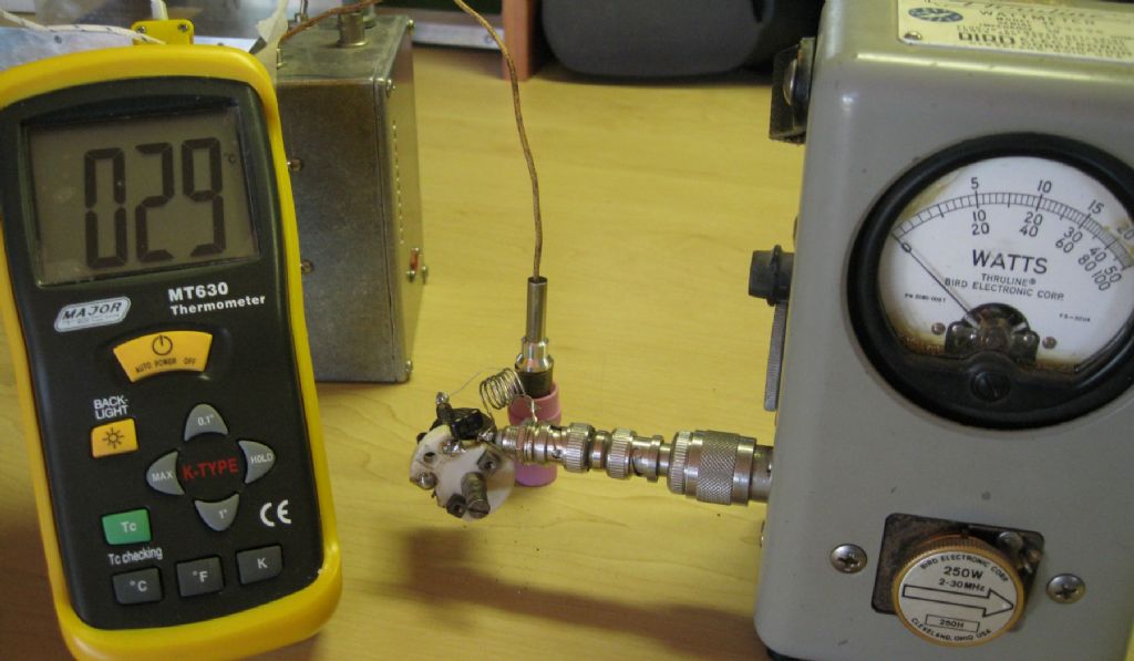
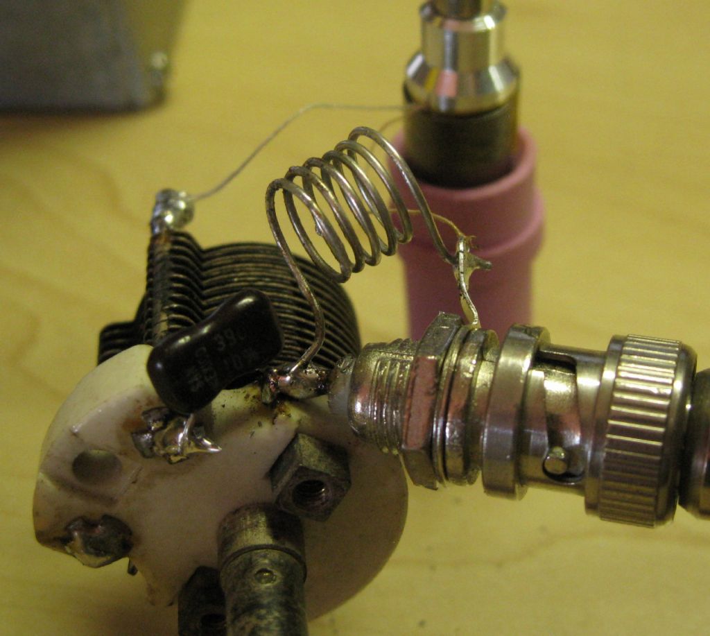
                                    Test setup – The hotend is the device sitting atop the pink ceramic thingy..The wire entering is the thermocouple

                                    test setup.jpg

                                    Top scale = 250watts FS – abt 38 or so watts in. (Reflected pwr = nil..)

                                    37watts13mhz_classc.jpg

                                    Around 45watts in ( amp is class C so fairly efficient)

                                    44wattsin.jpg


                                    After 15sec15sec.jpg


                                    After 20sec

                                    20sec .jpg

                                    After 50sec

                                    50sec.jpg

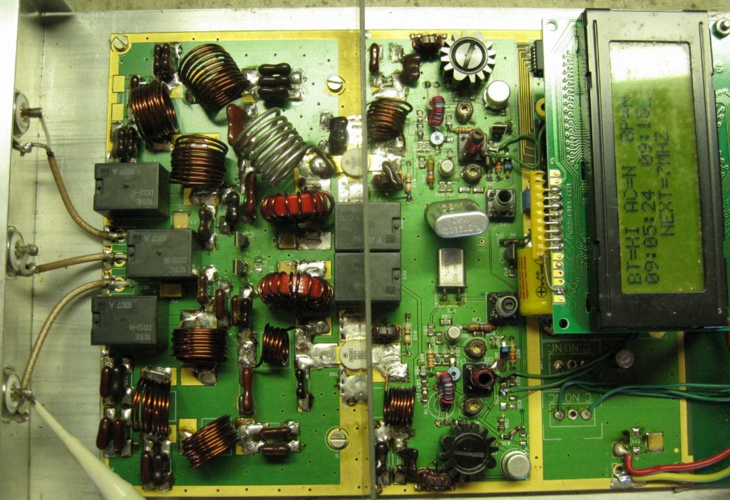
                                    The RF signal source – Two amps in one – 7MHZ and 10MHz, latter changed to 13.5MHz for this test

                                    cw signal source.jpg

                                    The test Matching network.

                                    match network1.jpg


                                    Matching network, some copper coils used with the low-frequency inverters – just cooked the coils due to skin effect and high currents needed to heat aluminium or stainless – insulation burned.match_coils_nozzle.jpg

                                    The test hotend- Wire is silver, 0.35mm diameter, 16turns 10.5mm diameter.

                                    nozzle_coil1.jpg

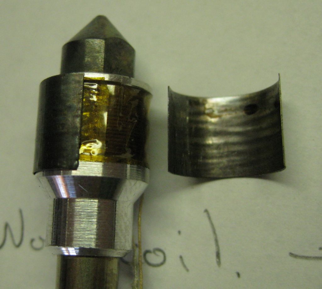
                                    uMetal shield for EMI mitigation..

                                    nozzle_umetalshield.jpg

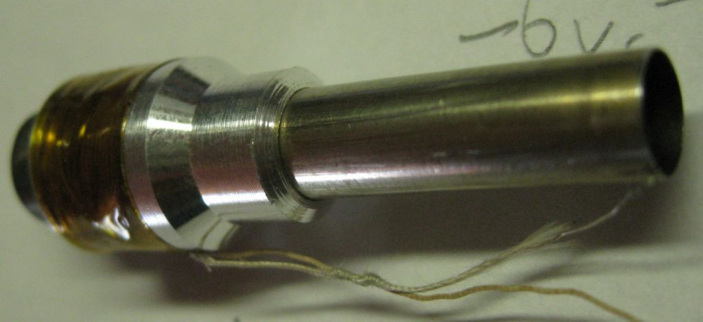
                                    The heat break end.

                                    nozzle3.jpg

                                    All in all a resounding success! Now to turn it all into a solid design..

                                    Joe


                                    Edited By Joseph Noci 1 on 22/07/2020 19:27:04

                                    #491640
                                    Joseph Noci 1
                                    Participant
                                      @josephnoci1

                                      The saga continues…

                                      Most of the effort of late has been on the induction heated hot-end. The previous tests showed promise, so a 'proper' hot end was designed and built, and a functional RF energy source made up and all tested. The PID control loop for temp control implemented and everything worked very well indeed. The RF source provides from 5 watts to 75 watts and heats the nozzle end from 25deg C to 200Deg C in 15 sec, and to 350deg C in 35sec. Set to 250Deg C , the PID keeps the nozzle with plus/minus 2 deg with a 40mm 12v fan wafted back and forth across the hot end and nozzle.

                                      Very happy with it all, but like the rest of the printer, a mission, and some much over the top…

                                      I was going to build a dual gear extruder as well, but am now impatient – hobbing the plastic filament drive teeth is too much for now! So looking to get one of those Bondtech extruders.

                                      Some photos:

                                      The RF energy source – power (2watt) oscillator source lower left, power amp transistor to its right, forward and reflected power measurement far lower right. The latter used in a feed-forward loop in the PID to calculate when to back off full power as setpoint temp is approached.

                                      img_0141.jpg

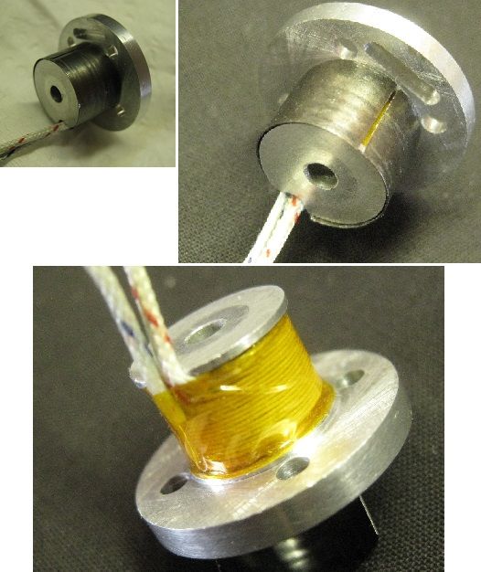
                                      The induction heating coil on the Aluminium hot-end.

                                      heat coil.jpg

                                      Coil assembly with thermistor. The long tube is the hot end mount and heat-break

                                      indheat part2.jpg

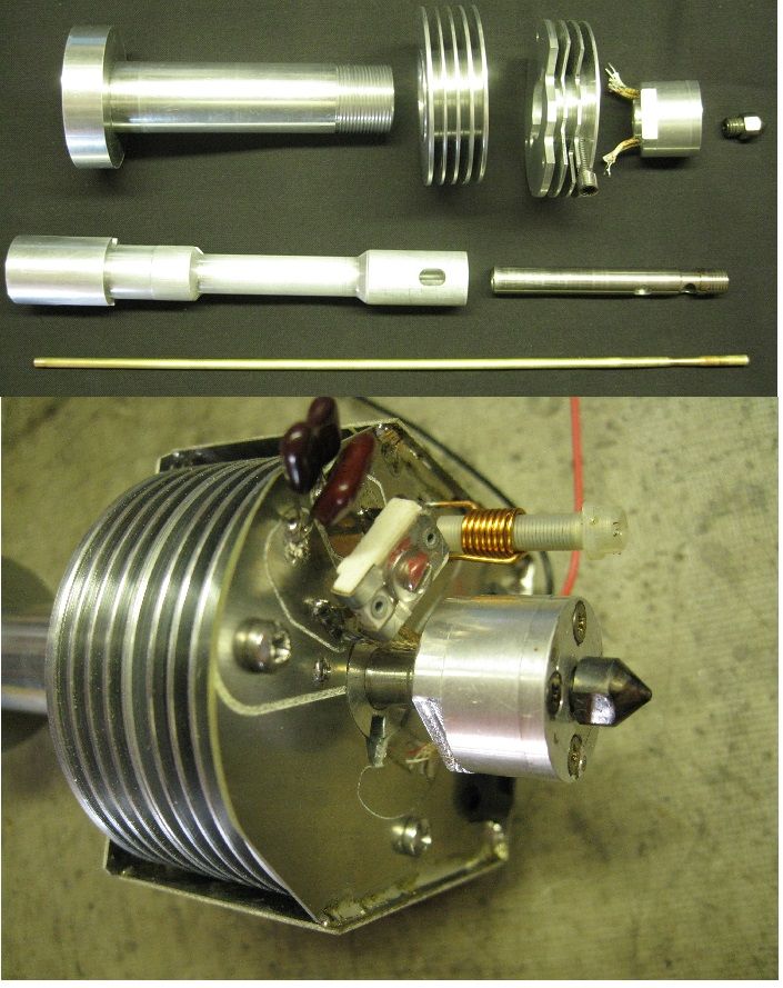
                                      Below images:

                                      top – various parts of the assembly, cooling fins, etc.

                                      Bottom – hotend fitted and RF matching being done to match the impedance of the induction coil to the RF generator output. The matching is via LC networks – these will be fitted internally later.

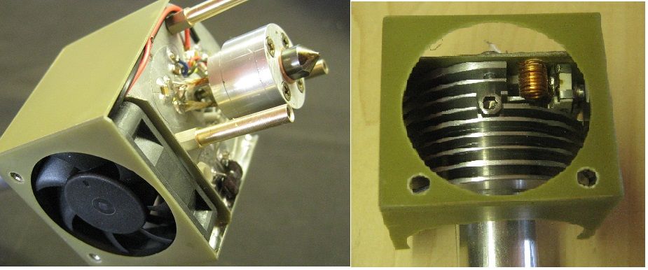
                                      parts and tuning.jpgHeat break cooling fan, and the matching components now fitted internally, behind the cooling fan.

                                      Housings made with 0.4mm FR4 PC board material – a favourite for housings, boxes, etc.

                                      partial views.jpg

                                      The completed assembly, with layer cooling fan fitted as well.

                                      fans and fins.jpg

                                      Now for an extruder to be fitted, and to get this lot into the printer cabinet and see what the thing can do!

                                      #494340
                                      Joseph Noci 1
                                      Participant
                                        @josephnoci1

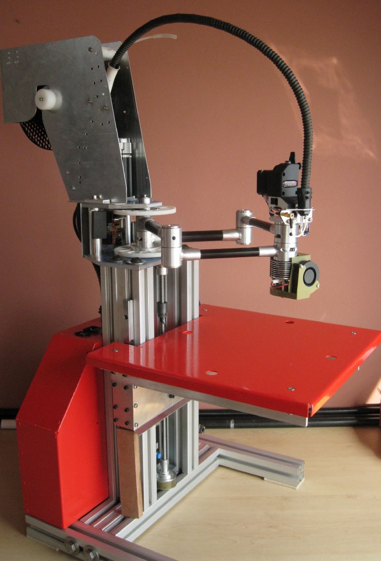
                                        Got to stop feeding Swarf to this thing…else this happens…ready to paint.jpg

                                        left view.jpg

                                        right view.jpg

                                        extruder1.jpg

                                        Wiring and Coax cable to the induction heated hot-end, the fans, thermister, extruder stepper, etc.

                                        extruder2.jpg

                                        filament1.jpg

                                        filament2.jpg

                                        Everything moves, drawing squares and circles with a pen in the hotend position looks very very good, hotend induction heating works fantastically well, extruder is a butchered Bondtech unit from a big creality printer.

                                        Next step to fit the bed heater, bed leveling sensor, and a Nextion based control panel so the PC is not needed.

                                        The leveling sensor to use the Texas LDC1101 – a very neat induction measuring device which will use a sliding ferrite rod ( 1mm diameter) that contacts the table and moves into the sense coil. The change in inductance ( a 24bit value) is easily converted to a distance measurement with 20um accuracy, with 5um resolution, from 40degC to 120degC

                                        Just another over-done sensor excercise…

                                        Joe

                                      Viewing 18 posts - 1 through 18 (of 18 total)
                                      • Please log in to reply to this topic. Registering is free and easy using the links on the menu at the top of this page.

                                      Advert

                                      Latest Replies

                                      Viewing 25 topics - 1 through 25 (of 25 total)
                                      Viewing 25 topics - 1 through 25 (of 25 total)

                                      View full reply list.

                                      Advert

                                      Newsletter Sign-up