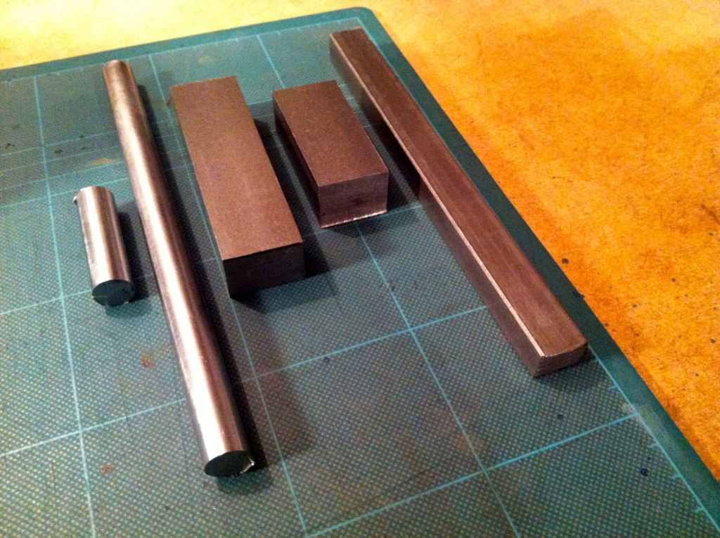
Starting to look at doing the Crankshaft now. As usual another first for me (from scratch) and a bit of a look at setting things up accurately. For a Lathe that cost half the price of the TV I can't expect anything great here but I thought it might be interesting to look back at some figures in the future when using different equipment.
I have no idea at the moment as to wether the following figures are good, bad or indifferent…
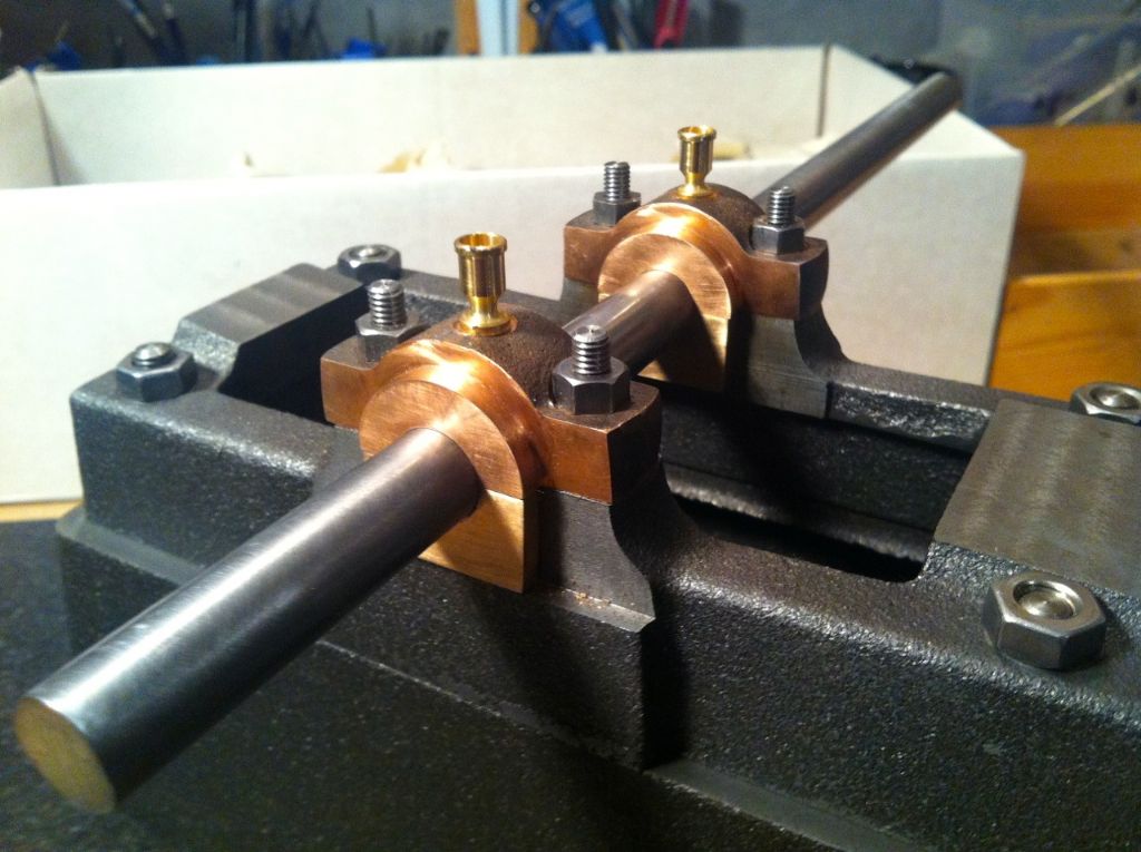
Likewise, I won't know whether I'm going about this the right way until i work my way through it… The first thing I wanted to do was to get the Crankshaft Axle a good fit through the reamed bearings – not least so that I can use the reamer for all the other Crankshaft bits… I decided to order a 1/2 inch PGMS Bar.
My 1/2 inch reamed bearings came out at 12.701mm. – measured with a bore gauge.
The PGMS Bar after polishing came out at 12.666mm – and it feels a lovely fit, no play at all. I'm guessing though that 1.5 thou undersize won't be considered good on here.
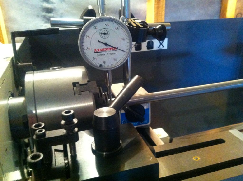
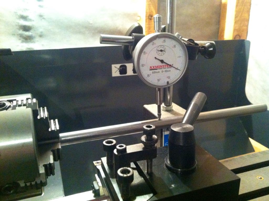
I was interested to see what my Chucks were like.
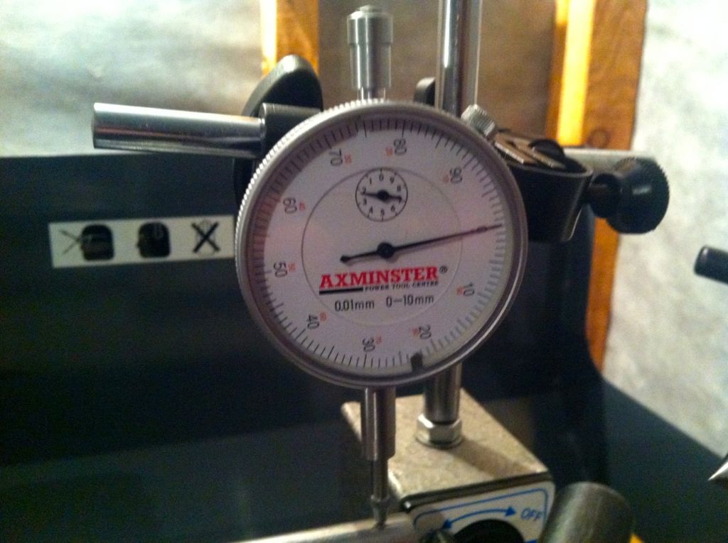
My 3 Jaw Runout figures with the PGMS 1/2" x 12" bar.
Next to chuck – less than 1 thou
Middel of the bar – 4.5 thou
End of the bar – 15 thou.
That didn't seem too good to say the least although when I took the chuck off there was some tiny bits of swarf on the 'back' fitting surface which may have made a difference.
The 4 Jaw setup with the same bar using the dial test indicator and same 12" length bar.
Next to the chuck – about 1 thou – my digital iphone converter won't convert to less than 1 thou..
Middle of the Bar – 0 thou.
End of the Bar – 4 thou.
I could have may be got it a little better, but not much I think.
Anyways it may be interesting to look back at these figures. As I don't need to turn the complete shaft it's maybe irrelevant here really…
Testing the Crankshaft Axle diameter. Feels like a great fit. 1.5 thou undersize to the bearings.
Regards
Allan
ps apologies if the videos didn't come out again.. (sorted by JasonB)
1.5 thou down is fine for a running fit for a 1/2" shaft, Tubal Cain recommends a thou plus 1.5 thou for every inch of diameter for a 'normal' running fit'.
Yes there is a length of smaller diameter to turn down – next I was going to use the 4 jaw with the work close to the chuck and put some centre holes in after setting with the DI …I'll post up the Crankshaft drawing next time…
and thanks, you've put the video's in again. Sorry I'll be getting a pain (yet again!).. I don't know what I'm doing wrong. I click on the youtube icon in the reply box, open a second browser window and go to the youtube page with the video on, click on share then click on embed, put the 450 in the width box then copy and paste the code into the reply box window as it says to – but all I get in the reply window then is a large empty window with 'iframe' written in red…
personally i would regard the fit quoted by neil as LMS rather than GWR and way too sloppy for my liking! bearings do bed in a bit once the machining marks have been worn off.
ive never been very fond of what Tubal Cain wrote!
Would have been no hope for me at GWR then! But that's interesting to hear as well…
I think I should say that I may have misrepresented my little Lathe yesterday – I thought to make a small 'split sleeve' to protect the Crankshaft while working on it and tried another 12" length of bar in the 3 jaw this morning before cutting from it to make.. The runout at the end of the bar (furthest from the chuck) was 6 thou, it looks like the swarf I mentioned yesterday behind the chuck did have an impact on the 15 thou figure I got then, I need to be more careful cleaning and will start making a note of the jaw positions when fitting as well now I think…
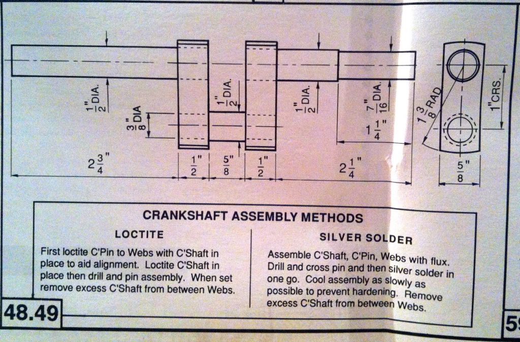
The Crankshaft Drawing..
Cutting a bar to make a split sleeve to protect the Crankshaft from the Lathe Dog while turning between centres and to allow holding for the centre holes to be faced out at the end, or so I'm thinking….
When I was training 50 + years ago, the standard clearance to aim at on a bearing was given as 1 thou/inch diameter, not 1 thou/inch diameter plus 1.5 thou. This would make a big difference in clearance on the size of shafts we are talking here.
Just a little record of making a 'Split Sleeve' for holding and protecting the Crankshaft while making it ..
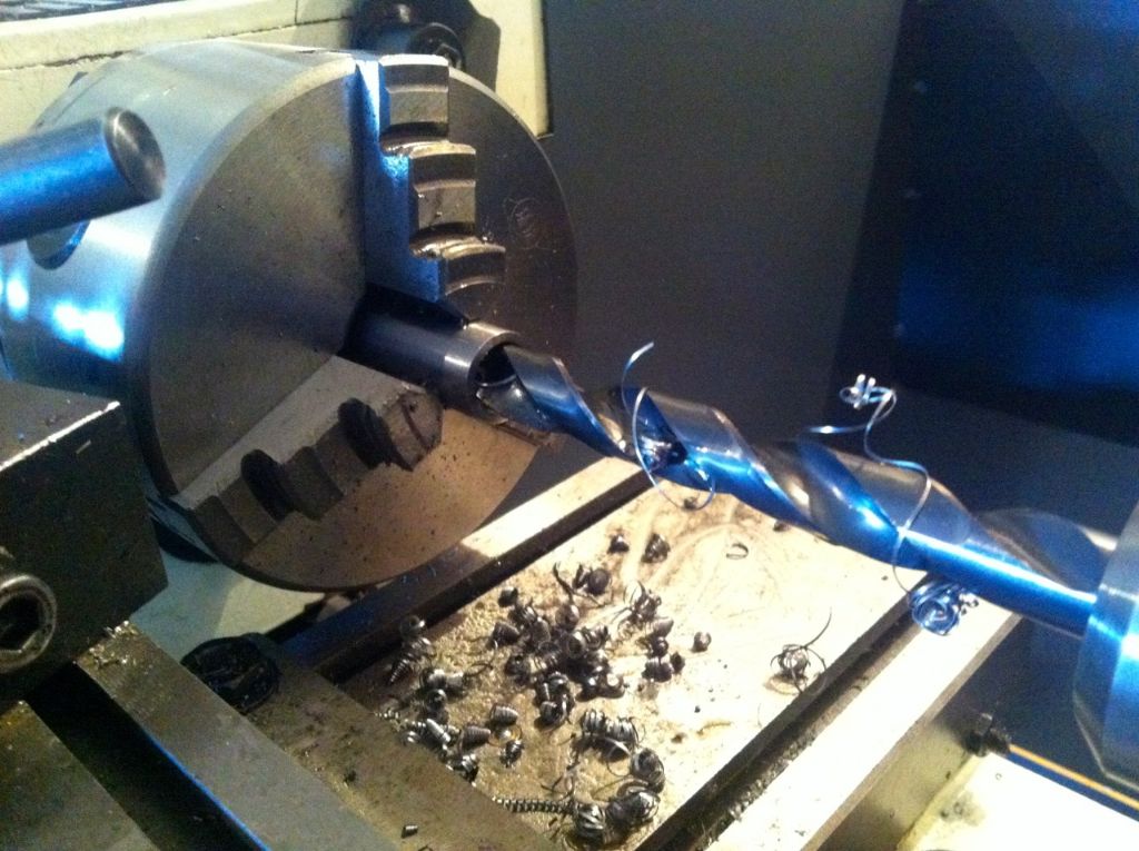
Drilling out the Sleeve after turning down some mild steel bar…..
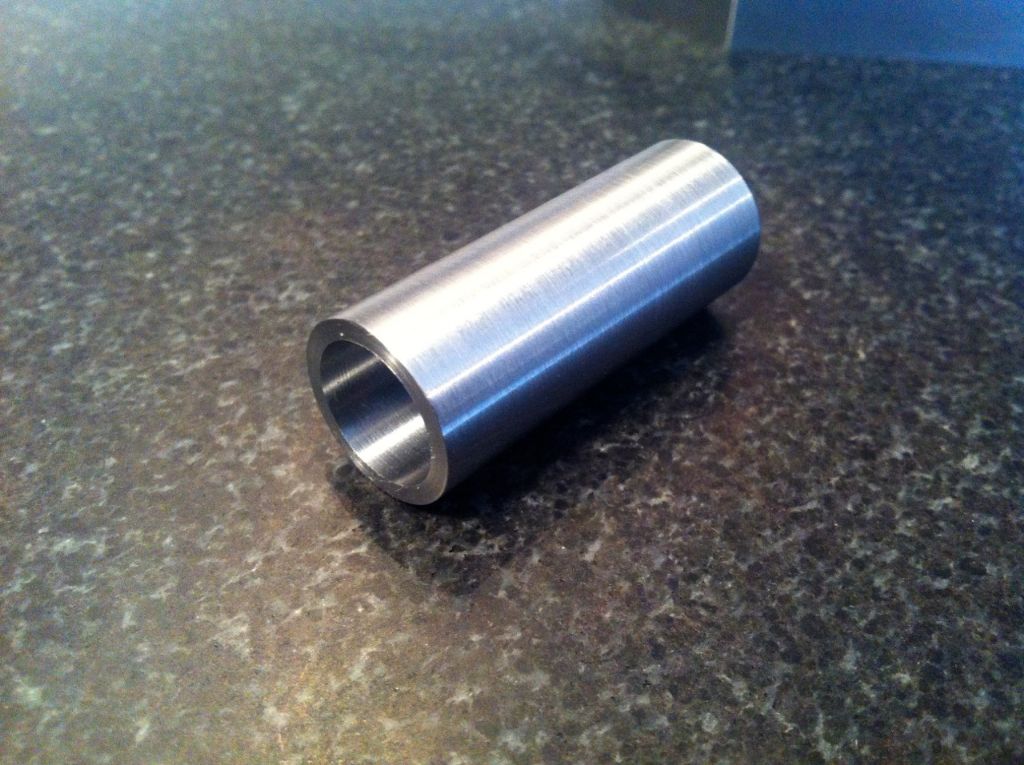
The Sleeve ready for splitting..
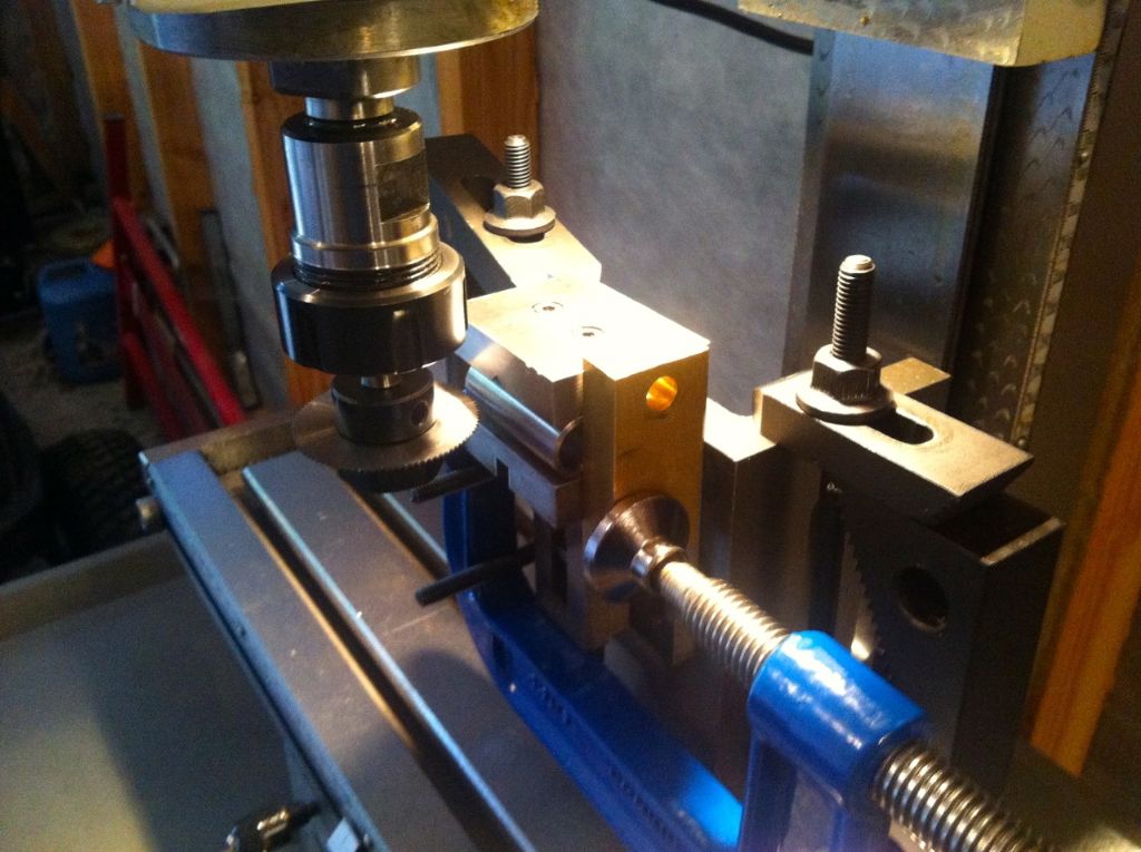
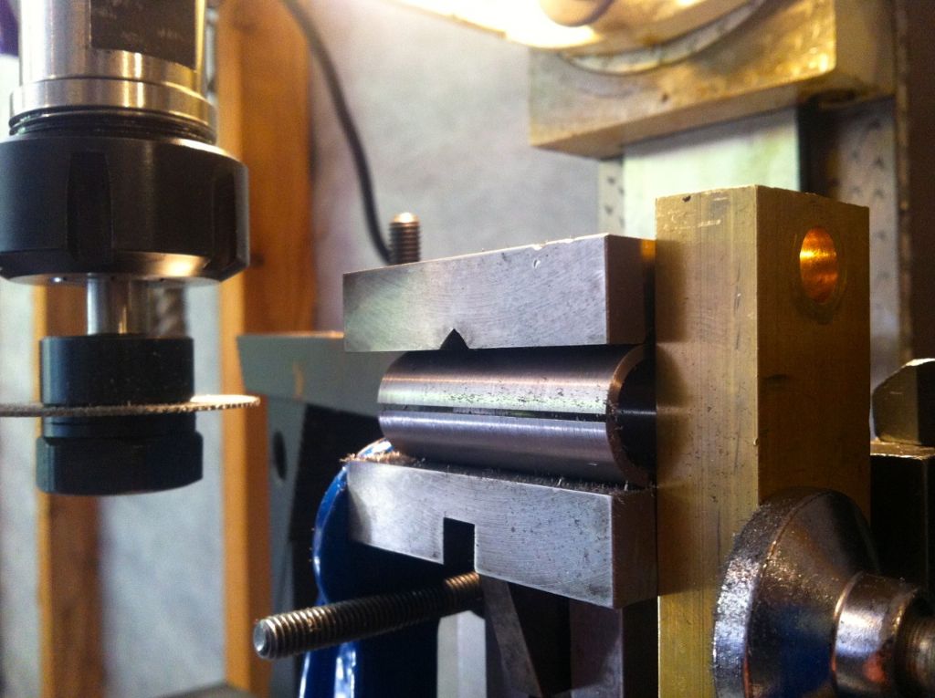
Setting up to split the Sleeve with the Splitting Saw.. I'm sure I over complicated this, but it did the job..
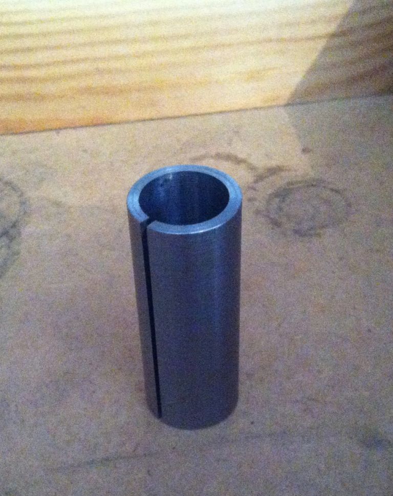
The Sleeve after splitting..
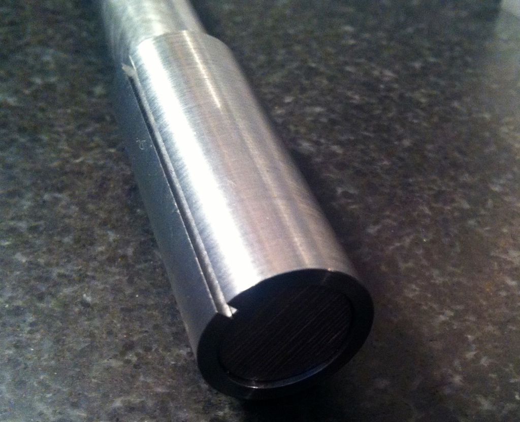
Test fitting the Protective Sleeve on the bar to be used for the crankshaft. With hindsight it may have been better to have made it a little oversize as its a close fit, I wont be using it to turn any diameters, just for protecting and facing out the centre holes – but its a good fit and will do the job as it is – and importantly doesn't mark the shaft..
The finished Sleeve.
Apologies – if i've used too many photos' for such a simple thing…
i would have clocked the crank material in the 4-jaw then turned down the 7/16" end.
i would advise the loctite method of making the crank shaft. you can simply same by not turning down the drive pin to steps but leave as 1/2" dia all the way.
Thanks Julian – yes some Loctite 638 arrived yesterday for the assembly. I thought to clock the bar in the 4-jaw and get centre drilled both ends to turn the 7/16 diameter and the Web sides between centres, then use the two 'throw plates' that I'm going to do next for the ends of the Webs and to skim the Crank Pin. All to make yet though..
Concur with ChrisH; when I served my apprenticeship I was also taught to aim for 1 thou' per inch shaft diameter, have done all my career & have taught apprentices the same.
As a point on work holding, that is not the best way to hold a tube when cutting through the tube. When the cutter cuts through the tube it can collapse slightly come loose while grabbing on to the cutter. In this instance it has worked but it would have been better to clamp the ends.
Thanks very much – I will be using this figure now in the future..
Hi Bob.
Again, thanks very much for this – reading your post it's obvious that you are right, why I didn't think to do it that way at the time I don't know, I even thought to clamp very lightly for that reason and was worried in case the work shot out the end of the vice as a result. I'll definitely do as you suggest in future.. Sometimes the brain just doesn't work!
Not much progress the past few days – TT week I usually end up spending my free time watching it over at least a half dozen times..
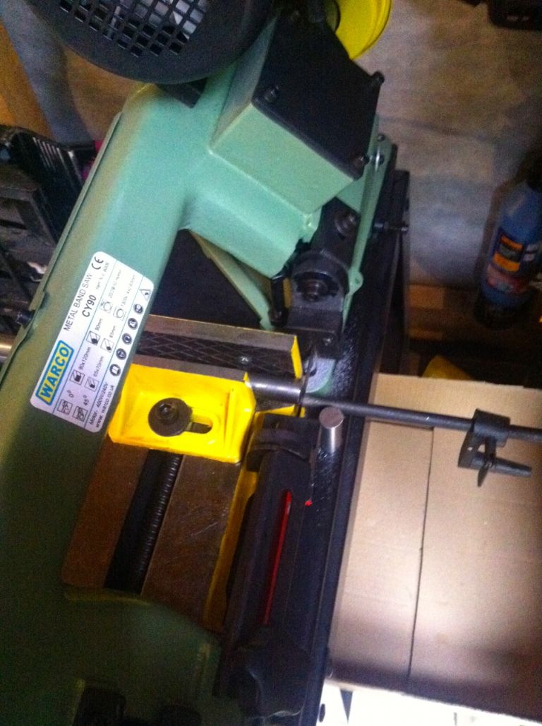
I did get some bits cut to approx length to make up the Crankshaft this morning – the Bandsaw doesn't get that much use but I was glad to have it to cut this lot earlier..
edit – I forgot to say that I had to take a skim (0.1mm) with the boring bar off the sleeve that I made – it was too tight, I had initially used the reamer. Now it seems perfect and slides, tightens and releases easily. Something I will know (0.1mm oversize) to do in future when doing similar..
Hi Allan, The no 1 is a lovely looking engine,and would appear to have some interesting machine set ups…One open question If I may…I would think a finished engine would require painting …I tested out the process on my boiler, high temp engine paint…I believe the error i made was that i did not apply etching coat prior to the hi temp coat as it just started to peel off with the heat from the double burner…[stuart 504]…also suggested to me that all parts be soused in ''acetone'' to de oil and clean parts.