My little engine (continued)

Advert

My little engine (continued)

Home Forums Work In Progress and completed items My little engine (continued)

Viewing 25 posts - 101 through 125 (of 602 total)
  • Author
    Posts
  • #189624
    GarryC
    Participant
      @garryc

      Hi Andrew, its good to hear from you. I'm not too concerned at the moment about how long things take and hope as Jason says it will come easier and quicker as time goes on, been making fewer mistakes recently which is a good place to start.

      If I'm ever to have a go at a steam loco though I need to change up a few gears (as well as improve a lot). Having a general interest in steam locos it would be really interesting not to mention great fun trying to see how far it was possible to get I think – and I'm thinking alongside making the stationary engines as well, long term project kind of thing – must be mad! I find traction engines quite interesting as well thinking about it – wish I had started this younger.. I guess there is a big step up in ability from making stationary engines to loco's and traction engines though, although I've seen some very complicated stationary engines as well..

      Looking at Jason's photo above, I can see the advantages of doing all in one more clearly now after going through it. I think Roy suggested doing it in 3 parts, can also see why that makes sense as well now. Both good advice – so of course I go off and try do it in two! Mental note to not only listen to those that know better – but to take the advice next time!

      Cheers

      Garry

      Edited By Gary on 12/05/2015 14:52:14

      Edited By Gary on 12/05/2015 14:56:55

      Advert
      #189855
      GarryC
      Participant
        @garryc


        My transfer punches set has turned up and I now have the column fitted – I can see they are going to come in very useful, should have got some before.

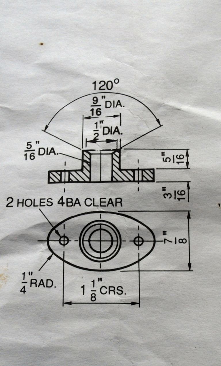
        Next the Piston Rod Gland. These are pretty much the same as I did for Victoria but much larger. Think I did the fixing holes on Victoria by eye as they were so small. As they are bigger this time I wondered how to do the them more accurately. The glands are elliptical and whereas I know how to find the centre and axes for an ellipse on a flat sheet of paper this is different of course. Setting the boss to run true on the lathe and drilling means you loose the centre to aid in finding the axis for the fixing holes later? The boss would seem to be in the way for marking out on the 'front' (parallel sets of chords etc) and if marked out on the back – well you need to turn from the boss side? Sorry I'm sure I'm being very stupid again. If anyone has any tips I would be grateful. Maybe I will have to do them by eye again.

        The Piston Rod Gland Drawing.

        293. the piston gland drawing..jpg

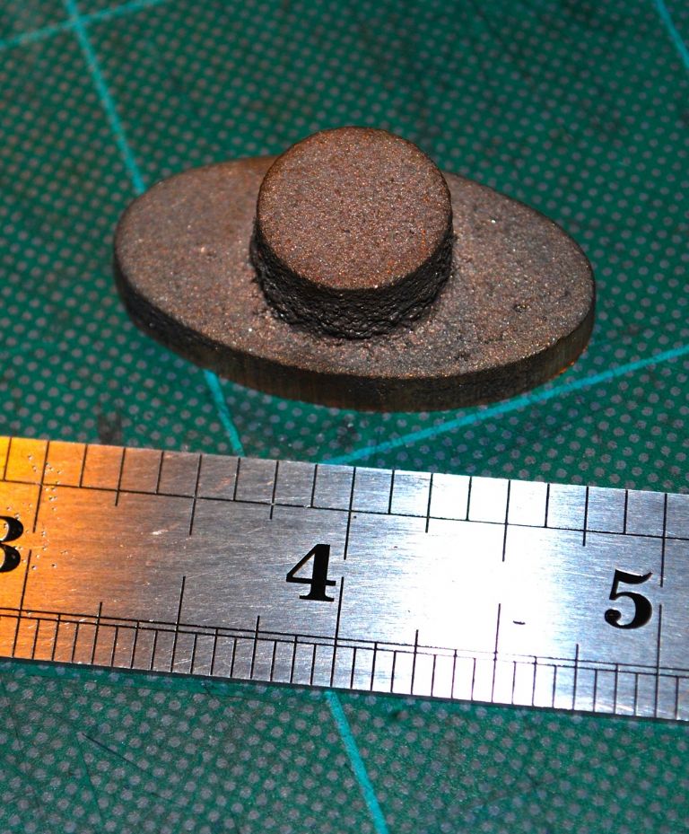
        The Piston Rod Gland casting.

        294. the piston gland casting..jpg

        Cheers.

        Garry

        Edited By Gary on 14/05/2015 12:48:25

        Edited By Gary on 14/05/2015 12:48:53

        Edited By Gary on 14/05/2015 13:04:27

        #189861
        Jeff Dayman
        Participant
          @jeffdayman43397

          You might try placing 2 vee blocks in a mill vise, and put the small end radii of the gland casting in the vees. The centres of the small radii (and hopefully the boss) will then be aligned along the long axis of the casting. After you find the centre of the boss along the long axis with wiggler or centre finders, the boss and side holes can be drilled accurately using the mill handwheel dials or DRO if you are lucky. No markup required – best kind of layout job!

          If you want to machine the side radii the easiest way is to make up a plate jig for the lathe and bolt the part to it via the side holes. The drawing does not note the dimension of the side (larger) radius so you'll have to calculate it of do a drawing on paper or CAD to figure out the centre and offset distance to mount the part off centre to the chucking shank on the back of the plate jig.

          The small radii will need to be done on a mill with a dividing head or just filed to shape.

          Good luck JD

          #189863
          JasonB
          Moderator
            @jasonb

            I really would not worry about the geometry.

            Hold in 4 jaw and get the spigot to run as true as possible then machine that to 9/16" dia and 5/16" long. Drill and preferably bore the hole and finish with a reamer, add the chamfer.

            Turn it around and hold grntly by the spigot to take it back to 3/16" thickness. Now while its still in the lathe blue the end and set it by eye so its as horizontal as possible and use the lathe tool to put a couple of hoizontal lines. Pop a bit of 5/16 rod into the hole and touch your tool against it then wind out 0.406" and gently rotate the chuck by hand so you swing two small arcs at 1.125" dia.

            Punch mark the two holes. Now you can drill the holes followed by making a couple of 1/2" filing buttons to shape the two ends and then just blend into the sides.

            An alternative way to mark out would be with a height gauge or scribing block first at ctr height and then with the point raised 9/16 a bit like I described here

            There are a couple of other ways to shape a gland either by offsetting in the 4-jaw or with a boring head but a bit of file work is all this needs for this one, the other methods are better if cutting from solid rather than using a casting, I'll find a photo or two later.

            J

            #189872
            GarryC
            Participant
              @garryc

              Hi Jeff

              Thanks very much for that, I follow your Vee Block and Mill Vice method – I wouldn't have thought of that! Unfortunately one of the mistakes that I made when first getting some kit to start with was that yes I did think to buy a couple of V Blocks, but not as a matched pair – it seems so obvious now but not back then! I should have mentioned it when I replied in Peters beginning Good/ Bad tool thread. I have to admit that the jig for the radii is a little above what I can contemplate at the moment but still very interesting though and much appreciated. I've only recently since watching Eric Vaalers video's starting setting the mill vice up properly each time not to mention actually getting an accurate mill vice as well – making a huge difference as you can imagine!

              Hi Jason

              As ever this is great and important to know as its so common, many thanks. I can follow that through bit by bit now and use again in future. I've been looking through some of your Gade build on the link you gave – what did I say recently about stationary engines being simpler than Locos and Traction Engines – well I got that wrong that's for sure! I must start to follow builds like this..

              Ta very much again.

              Cheers

              Garry

              #189877
              BERT ASHTON
              Participant
                @bertashton57372

                In the past I machined the glands thus, grip spigot in the 3 jaw chuck and take a clean up skim,

                then drill and ream to size, mount on the end of a short piece of brass rod with Loctite, the diameter

                and face can now be turned.

                If the lathe speed is now dropped to its lowest a smooth file will clean up the ellipse edge, with care

                of course, If you know your lathe centre height the gland can be set by eye and your height gauge

                set at lathe centre a line can be scribed across the gland, then turning the chuck thru 180 degrees

                scribe with the height gauge set to the hole centres.

                I hope this helps,

                Bert Ashton

                #189878
                BERT ASHTON
                Participant
                  @bertashton57372

                  I forgot to mention that gentle heat applied to the brass rod will soon free it.

                  Bert Ashton.

                  #189892
                  GarryC
                  Participant
                    @garryc

                    Hi Bert, nice to hear from you.

                    Again for me there are some really interesting things there to take note of not just for the gland job, thanks. I would never get to know things like you suggest were possible without hearing it on here…

                    The phrase 'knowing your lathe's centre height' has come up a few times now but its not 'registered' as it should have done until now for some reason – I'm assuming we are obviously not talking about the advertising specs here. I'm beginning to see how useful knowing this is and could be different for the same model lathe. I'm assuming that we are talking about an accurate measurement from the surface of the cross slide to the line between centres? So if I were to measure with my height gauge on the cross slide the height to the top of my test bar when its between centres less half its diameter that would give the measurement we are talking about for my individual lathe? ummm now thinking of course I should have thought about doing this ages ago…!

                    Thanks Bert, its always great to be thinking and learning new things.

                    Cheers

                    Garry

                    Edited By Gary on 14/05/2015 17:03:00

                    #189895
                    JasonB
                    Moderator
                      @jasonb

                      The way I did mine was to blue two opposite sides of the faceplate, set height gauge to near as ctr as I could and put a mark either side of the faceplate. Rotate 180 deg and set the mark nearest you to match the height gauge than scribe a line at the rear. you will get two lines. Keep repeating from the start until both lines meet and you will have it. Your test bar less half dia would be a good starting point. I have it written on the wall behind the lathe 3.389"

                      While you are writing on the wall make a note of the belt numbers for the lathe as by the time it fails the number will have worn off and you will save having to work out what it is.

                      #189903
                      GarryC
                      Participant
                        @garryc

                        What a great post Jason – That's just got to be my first job now in the morning! Cheers..

                        #189915
                        JasonB
                        Moderator
                          @jasonb

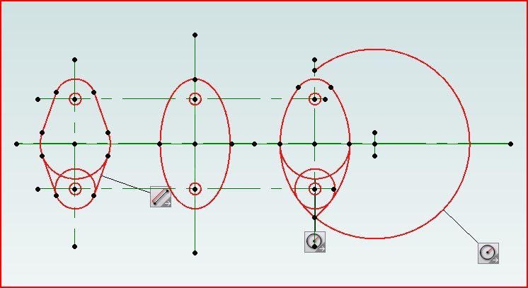
                          Had a bit of a play with Alibre. In the middle is a true eliptical gland, on the left one that links the two 1/4" R ends to a 7/8" dia central section with straight tangental lines linking the two and on the right one that joins the 1/4" R ends with an arc. I have left a few lines so you can see how they are constructed.

                          glands.jpg

                          The true elipse could be drawn out and then transfered to the part or cut with a CNC.

                          The flat tangental line one is quite easy to do with a rotary table first cutting one straight edge then rotating around the 7/8" dia followed by the other straight edge. Turn 180deg and repeat then setup and do the ends. Description and photos here.

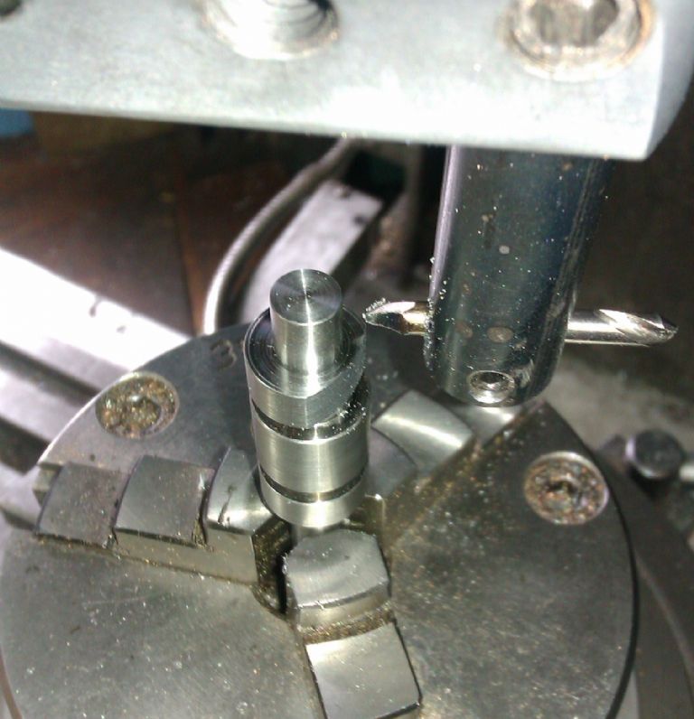
                          Looks like the only photo I have of the last method is out of focus and thats why I could not find where I uploaded it. But you can either screw the gland to a big lump of metal so the middle of the centre is at the radius of the large circle and then mount in the lathe which will cut one side, unscrew and refix to do the other followed by filing buttons to do the ends. Or you can centre it on the mill and then set the boring head to cut an external face and set the dia to that of the large red circle, this is not a gland but you can see how it gives the curved edge.

                          imag1507.jpg

                          And two completed "castings" and glands done with a boring head

                          #189922
                          Neil Wyatt
                          Moderator
                            @neilwyatt

                            This photo may provide a drop of extra inspiration.

                            neil

                            photo 39 shaping elliptical gland.jpg

                            #189923
                            GarryC
                            Participant
                              @garryc

                              Hi Jason

                              Firstly the photo of the two completed castings and glands are gorgeous! If only!

                              The gland diagrams I found very interesting and surprisingly (for me I mean) I can follow much of it, maybe even all I think. I'm sure doing in practice is another matter altogether and would need lots of practice but its good to begin to get an idea of how such things are done, very useful to see all of that. I don't yet follow how boring heads are set up for such things though. Best to try / start with some hands on at some simpler radii and the rotary table first I think. You've given me enough of an understanding of how to go about it to give it a go now, thanks!

                              It may be late in the day now, brain cells shutting down and all that – I've been thinking about finding the lathe centre height tomorrow and having trouble getting my head around how to rotate the faceplate exactly / accurately by 180 degrees?

                              Don't want to be a pain so don't worry, I'll probably wake tomorrow thinking more clearly…

                              Cheers

                              Garry

                              #189924
                              JasonB
                              Moderator
                                @jasonb

                                Should probably read "rotate the faceplate approx 180deg until the mark now at the front matches the hight of the gauge"

                                I'll mock it up and take a couple of pics in the morning.

                                Edited By JasonB on 14/05/2015 20:37:23

                                #189926
                                GarryC
                                Participant
                                  @garryc

                                  Hi Neil

                                  That's a great photo, very interesting again to see. Its unbelievable at just how many ways there are of doing these things! No wonder workshop apprenticeships used to be so long with so much to take in.. Cheers.

                                  #189928
                                  GarryC
                                  Participant
                                    @garryc

                                    ah Jason, I think I see now. Sounds like a case of moving the gauge in the right direction each time until the lines match – I'll give it a go in the morning…

                                    Cheers

                                    Garry.

                                    #189965
                                    GarryC
                                    Participant
                                      @garryc

                                      Thanks Jason.

                                      Just spent a very useful hour or so

                                      Centre Height – 74.96mm – 2.951"

                                      Low Speed Belt – M27

                                      High Speed belt – M31

                                      Motor belt – M25

                                      Cheers

                                      Garry.

                                      ps I have it on here now as well in case I loose it!

                                      (Ctr height checked 5 times incl gauge being zeroed in between to make sure its right and repeatable – it is!)…

                                      #190096
                                      GarryC
                                      Participant
                                        @garryc

                                        Can I just ask a quick question – as I'm waiting on a 5/16" reamer to do the gland I thought I would do the 1/2" filing buttons and harden them. Can anyone tell me how much to heat them and do I just allow them to slowly cool naturally. The bar I'm using is a bit left over from the supplied one for the Crankshaft and described on the drawing as Mild Steel.

                                        I have some info in Peter Wrights book 'Model Engineering' but he describes so many different treatments its difficult to follow..

                                        Thanks for any advice.

                                        Cheers.

                                        Garry.

                                        #190098
                                        Clive Hartland
                                        Participant
                                          @clivehartland94829

                                          Garry, you can only harden tool steel, that is carbon content steel. You can case harden mild steel but your filing buttons require steel with carbon content like silver steel. Your mild steel offcut from the crankshaft is no good for what you want to do. Obtain some silver steel rod for your buttons. That is unless you have some case hardening compound. To harden the silver steel, heat until cherry red and dunk it in oil or water, it will be glass hard and suitable to use as a filing button. To clean it up just use fine emery. Someone will be along soon to give you other ideas.

                                          Clive

                                          #190100
                                          GarryC
                                          Participant
                                            @garryc

                                            Thanks Clive. I think that explains why I was having trouble getting the info from the book.

                                            Shame I was quite looking forward to having a go with the torch again later!

                                            I've learnt something new already today – cheers.

                                            Garry

                                            #190109
                                            Anonymous

                                              Personally I don't harden filing buttons, but treat them as a disposable item.

                                              Andrew

                                              #190116
                                              GarryC
                                              Participant
                                                @garryc

                                                Hi Andrew

                                                Yes I'l just go ahead and do them with the Mild Steel and see how they last as is. I know now to order some silver steel for them in future.. Think I would prefer to build a collection of them that would last rather than do new ones each time – it'l be interesting to see the difference the hardening makes..

                                                Cheers.

                                                Garry

                                                #190123
                                                Anonymous

                                                  May be it's just a personal thing, but I prefer to make new filing buttons rather than have to buy new files. wink 2

                                                  Andrew

                                                  #190127
                                                  JasonB
                                                  Moderator
                                                    @jasonb

                                                    Same as Andrew I leave them soft and that keeps my files sharp

                                                    #190132
                                                    JasonB
                                                    Moderator
                                                      @jasonb

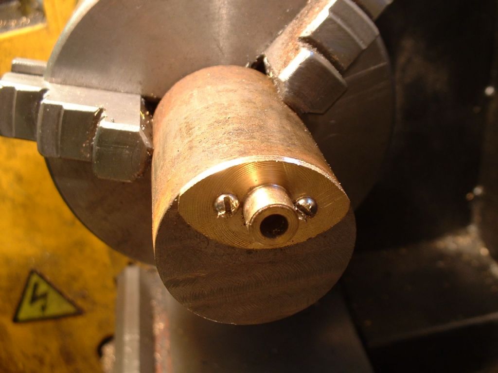
                                                      Bit late but I found this photo of the boring head being used to do a gland, the washer is to save catching the chuck jaws

                                                    Viewing 25 posts - 101 through 125 (of 602 total)
                                                    • Please log in to reply to this topic. Registering is free and easy using the links on the menu at the top of this page.

                                                    Advert

                                                    Latest Replies

                                                    Viewing 25 topics - 1 through 25 (of 25 total)
                                                    Viewing 25 topics - 1 through 25 (of 25 total)

                                                    View full reply list.

                                                    Advert

                                                    Newsletter Sign-up