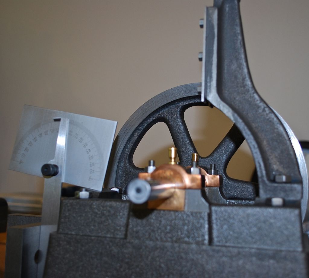
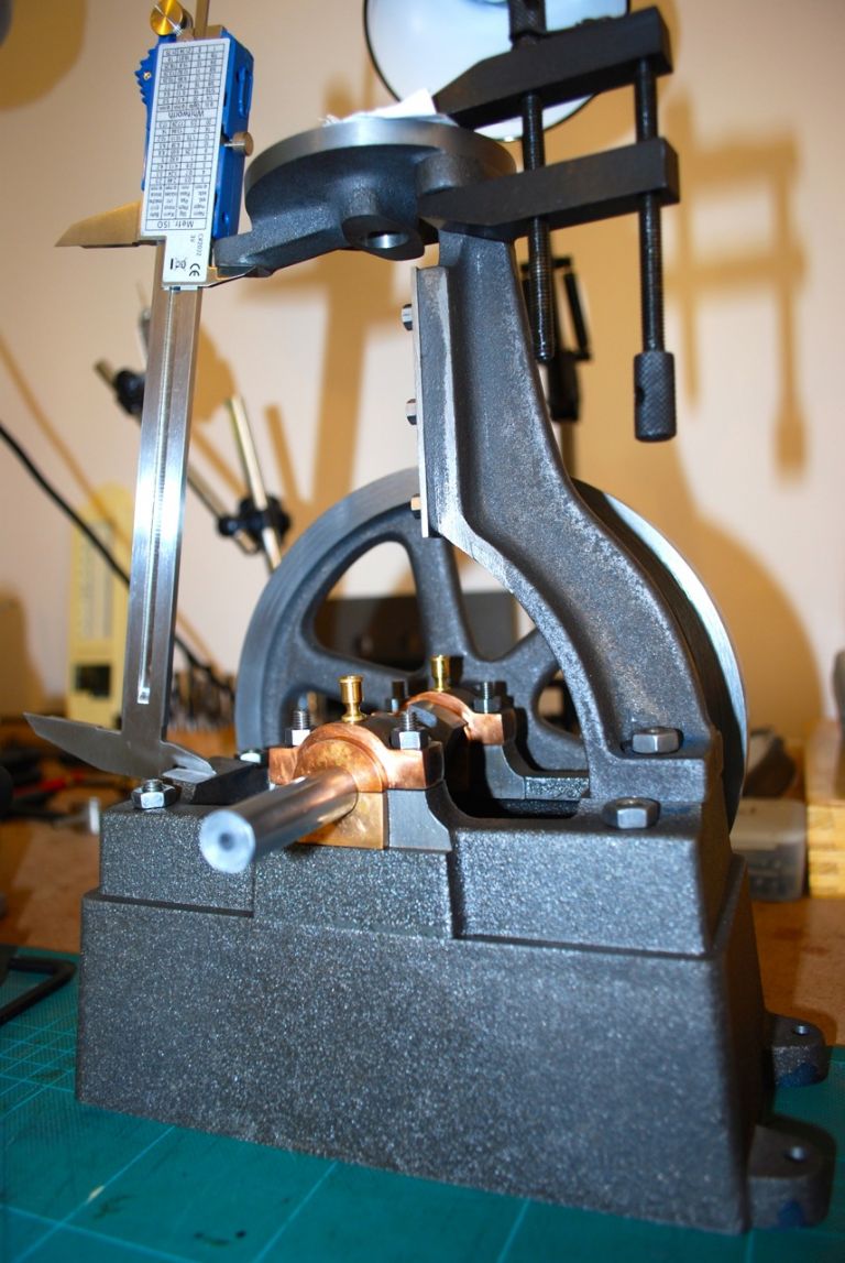
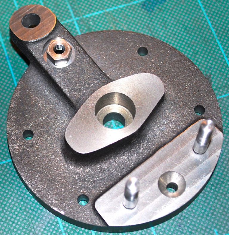
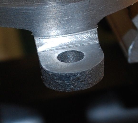
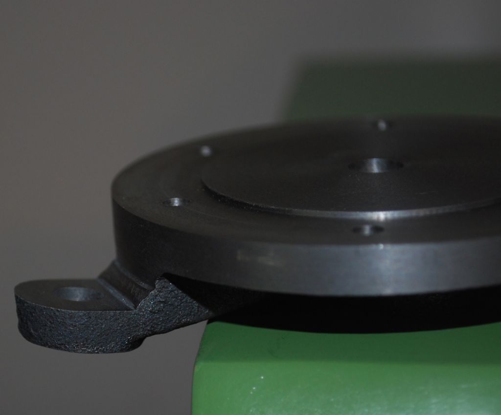
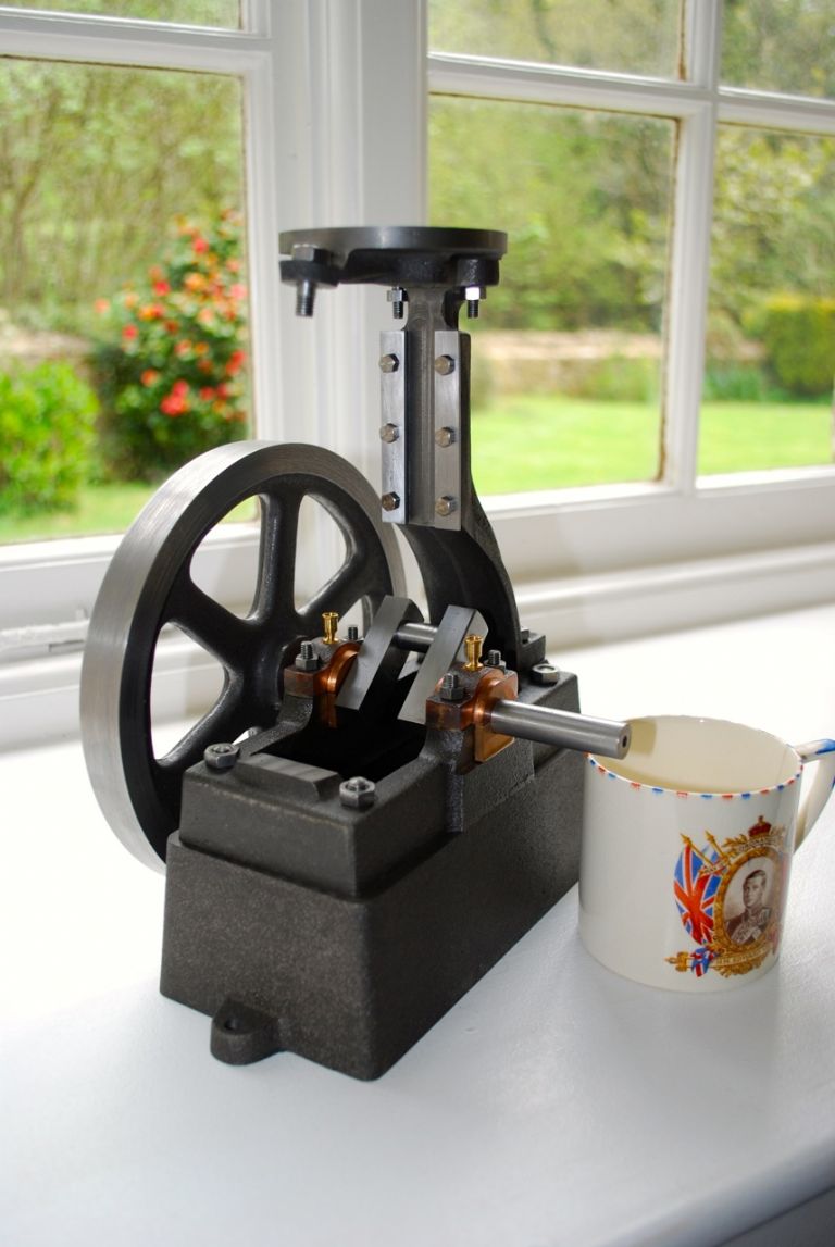
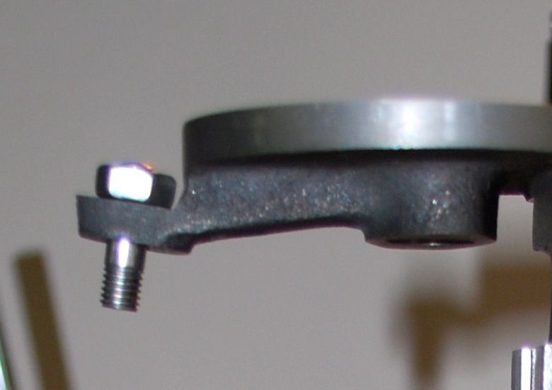
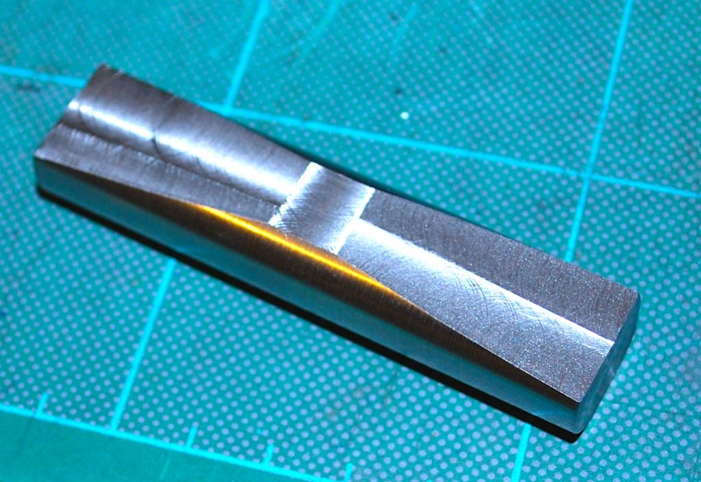
Time to get back on with the engine. After watching Eric's video's its clear that earlier in the build I didn't square off the bearing blocks properly which I think contributed to the solder failing when tightened in the chuck. They were definitely not square, out by a tiny bit – "that's the best the equipment can do" I remember thinking and I thought they would be ok at the time – hopefully I know better now… So anyways I thought I would make the little 'holding' tool / bar that he was recommending before going about squaring the supplied bar for the column and using his method. Its just a piece of bar with some flats – 2 parallel and two tapering for supporting a part when squaring off..
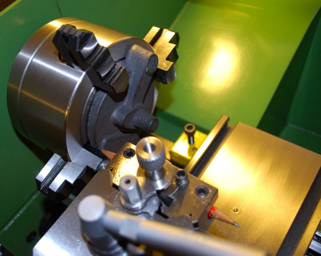
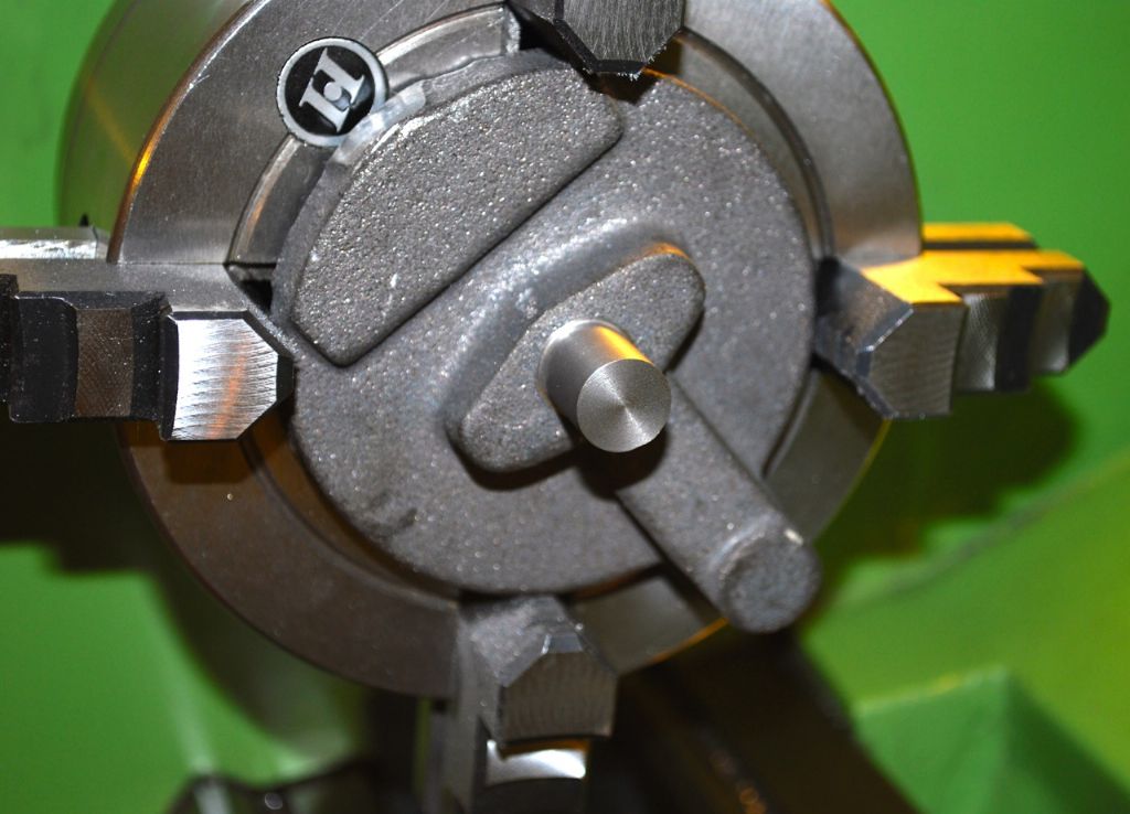
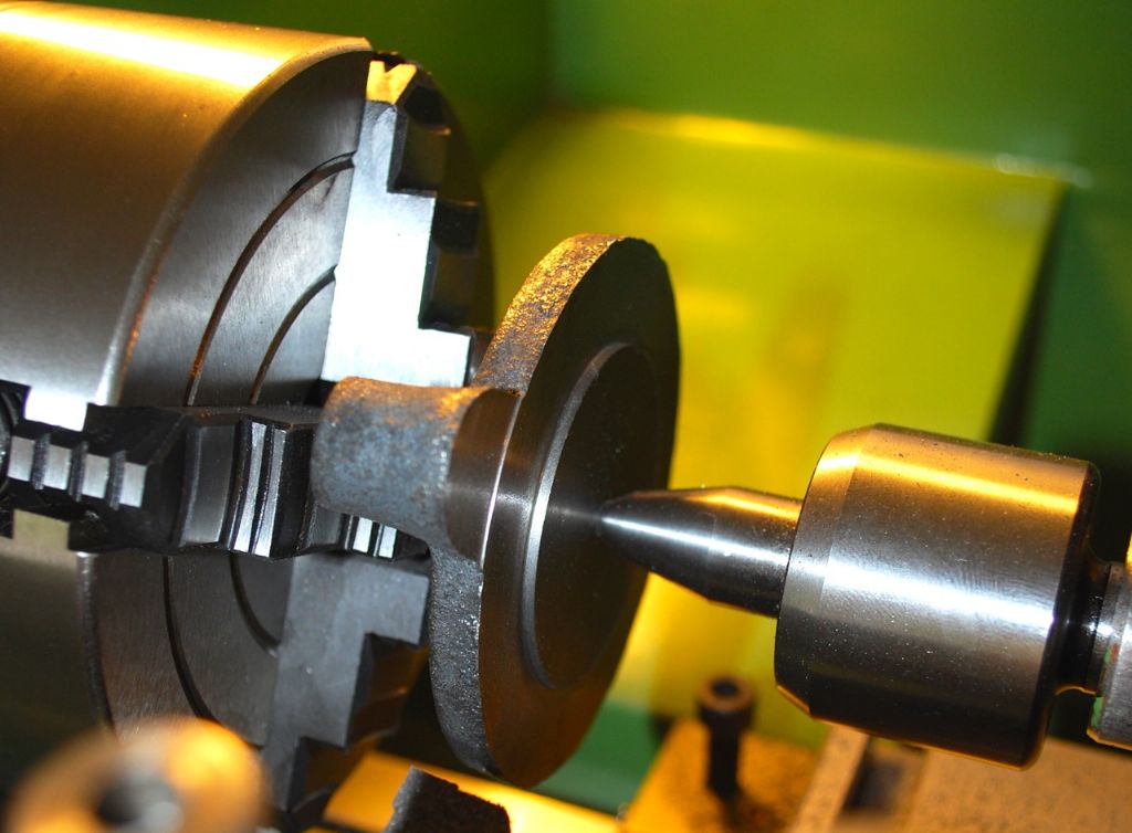
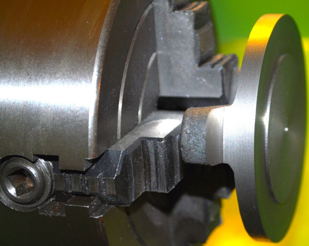
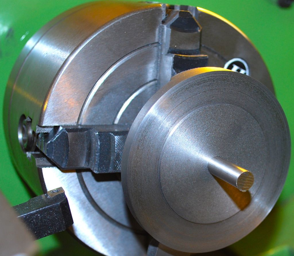
It didn't take long to do and should get lots of use I hope. I'm sure there are lots of different ways of squaring a part off but this looks like a good idea to me and you have to start somewhere. It doesn't have to be sized exactly but I need the practice… First time I've tried for a nice finish on the new lathe and easily the best I've ever achieved – indexable tip but with the tool angled over to the tailstock CCMT 06/04/02 I think. I can't get them to give any kind of finish if presenting at 90 degrees to the work which seems odd somehow..
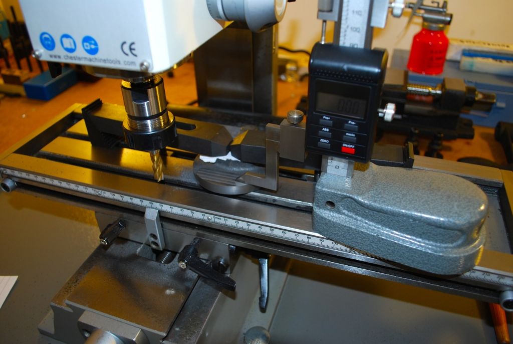
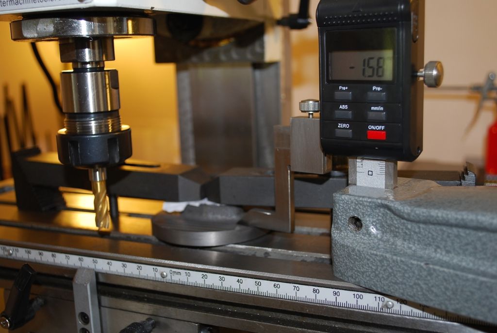
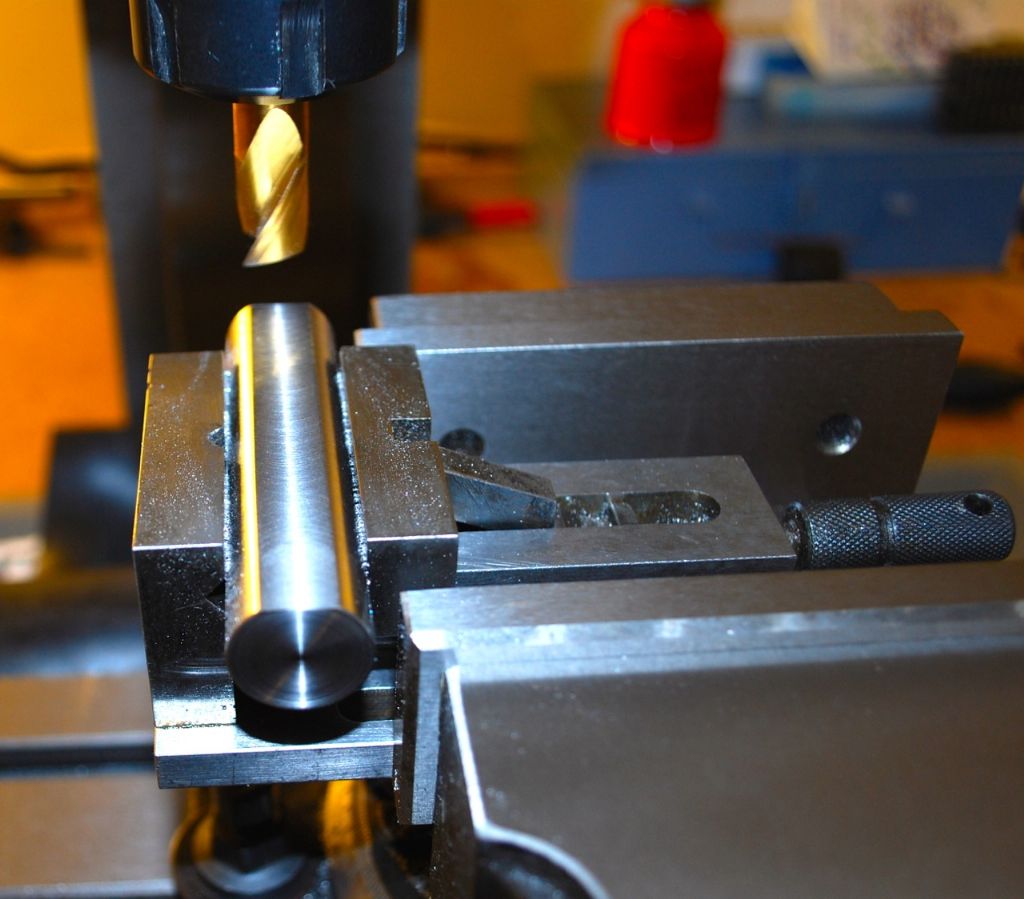
Putting the flat down one side of the bar – this side goes against the fixed vice jaw (.the back one)

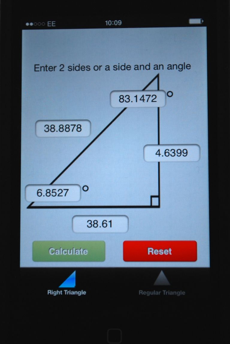
Didn't have to do this but decided to aim for the tapered flat going to 25% depth of the diameter – so used my little Trig App to get the angle, aiming for the tapers to meet tin the middle and then to put a flat across them. This small flat sits against the part. The 6 degree angle was the one I needed to find. I'm not saying the figures are exact, but for anyone interested in the figures – from my scribbles I can see the bar was 77.22mm long. The two sides at right angles are the known ones.. Diameter 18.57mm.

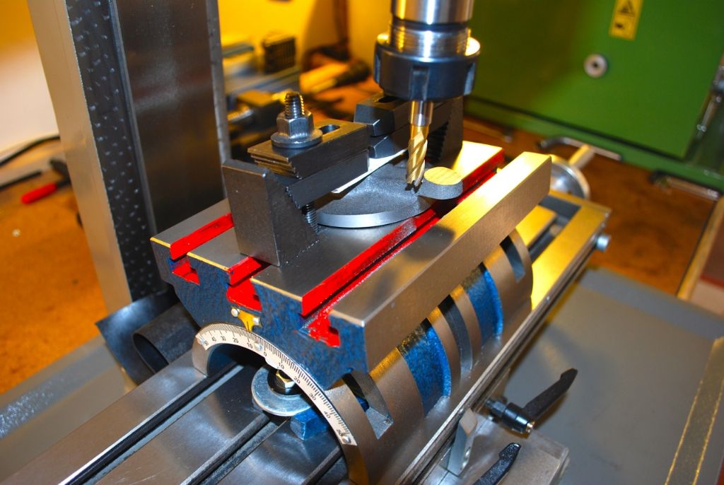
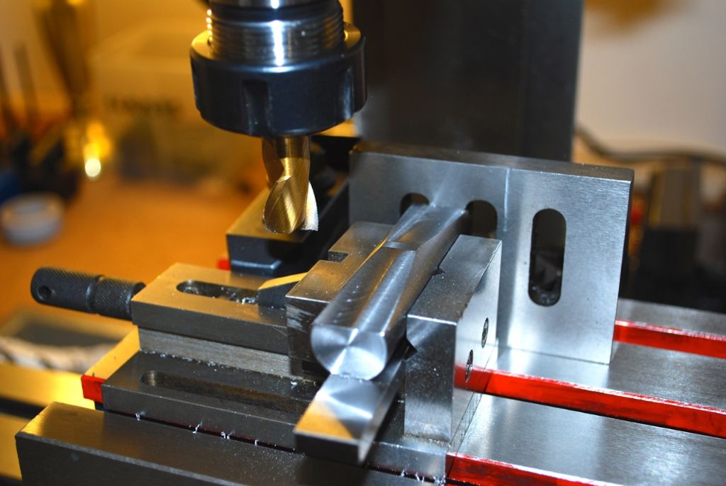
Putting in the small flat parallel to the long one.

The finished tool / bar.

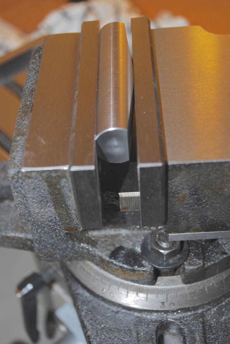
The tool / bar in the vice jaws. Vertex Vice.

Still working on the assumption of course that its only other beginners who will look at this thread…
Sorry if I've waffled on a bit over such a simple thing..
Hope it was of interest to someone…
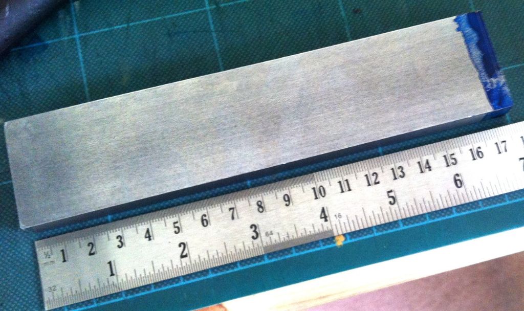
Next to grind a tool for the flycutter to use on the bar for the column – I've not used one yet..
Regards
Allan.
Edited By Allan. on 02/05/2015 16:22:19
Edited By Allan. on 02/05/2015 16:25:18
Edited By Allan. on 02/05/2015 16:27:47
Edited By Allan. on 02/05/2015 16:39:55
 JasonB.

