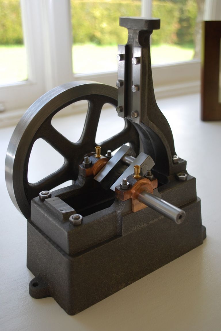
My little engine (continued)

Advert

My little engine (continued)

Home Forums Work In Progress and completed items My little engine (continued)

Viewing 25 posts - 26 through 50 (of 602 total)
  • Author
    Posts
  • #183544
    GarryC
    Participant
      @garryc

      Hi Ian

      Yes sounds like a good thing to do and I really like the idea of trying to make some tools – I'm more than a bit slow in getting things done at the moment though so tend to prefer to use the time I have to take the engine forward.. Maybe one day I'll have a go..

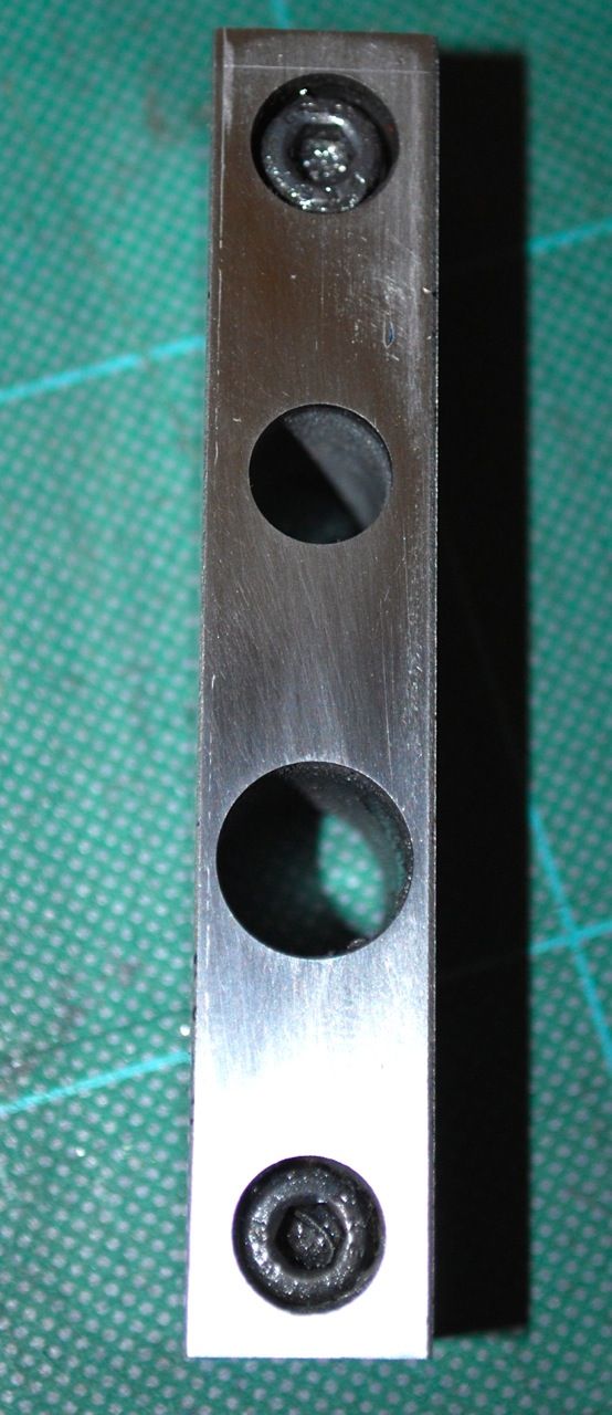
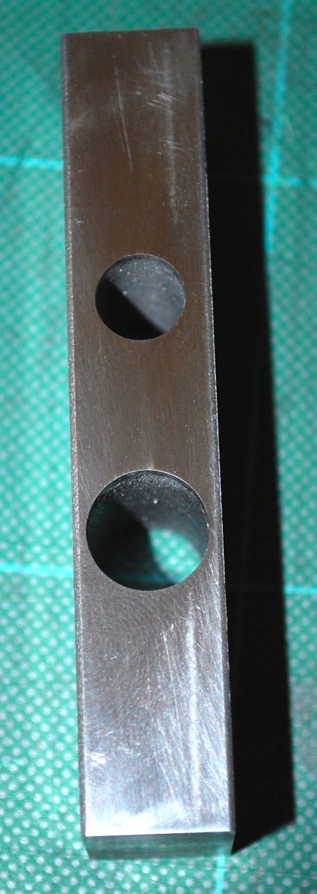
      Just a couple of photos of the Crankshaft Webs after drilling on the lathe earlier, need to turn the shaft next and then get them fixed to it..

      The top and bottom faces showing uppermost in the pics will be machined when between centres on the lathe later and will get rid of the tatty 'chamfers' which can tend to make the holes look out of position at the moment.. The bar for the webs as supplied was actually undersize, something I've noticed a few times now with other parts on this engine and Victoria – would have been nicer I think to have had a bit more metal to machine down to a clean surface from scratch..

      Side 1.

      216. the crankshaft webs after drilling side 1..jpg

      Side 2.

      217. the crankshaft webs after drilling side 2..jpg

      Regards

      Allan.


      Edited By Allan. on 17/03/2015 15:08:07

      Advert
      #183556
      Harry Wilkes
      Participant
        @harrywilkes58467
        Posted by Martin Millener on 16/03/2015 17:01:15:

        Yes, a lot of interest Allan – please keep posting

        I'll second that keep them coming smiley

        #183617
        GarryC
        Participant
          @garryc

          Thanks for that Harry its good to know there are some following. Your Traction Engine looks superb, I wouldn't know where to start!

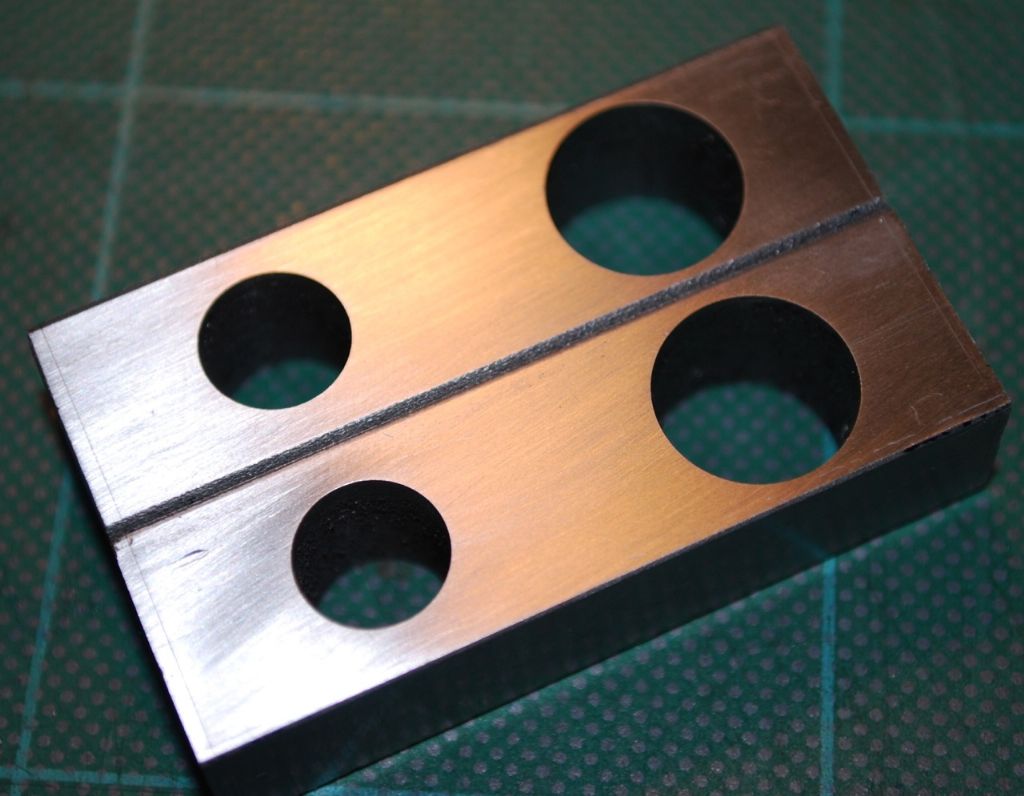
          No chance to do much today, but earlier I got the webs ready for the shaft & crank pin. Left far too much on the ends so more work on the lathe but better safe than sorry I thought..

          The two screws just cut away with a hacksaw and tidied a bit with a file. The pins will go in through the sawed ends. I'll radius the ends when I have the crankshaft between centres so they will be at 90 degree to the drawing..

          218. the crankshaft webs so far..jpg

          Next to get the main axle and the crank pin faced to length, centre drilled and onto unboxing the faceplate…

          Regards

          Allan.

          #183623
          GarryC
          Participant
            @garryc

            oops my mistake thats wrong above, the end radius will be as per the current drawing – thats me following some older guidelines. (sorry I did try to edit but couldn't for some reason)

            Cheers.

            Allan.

            #183788
            GarryC
            Participant
              @garryc

              Just the Crankpin today..

              No problem with this, just the 3 separate diameters to turn & face to length – I did this in the 3 Jaw Chuck, it will get skimmed again between centres when it is all together…

              Finding the new Lathe superb and very accurate, my Mic is a decent one now (M&W), I certainly couldn't do anything inside of 1 thou on the old one (down to me though somehow I'm sure), but I can now…. great.

              Progress with the Crankshaft so far..

              219. the crankshaft so far..jpg

              Cheers.

              Allan.

              #185083
              GarryC
              Participant
                @garryc

                Been making slow progress with the Crankshaft but finding it very interesting as a first attempt. I've made lots of mistakes that I may as well include here in case its of interest to anyone else first time around.

                First off as I had already used the supplied bar I tried to turn one from my own stock (larger diameter) which turned out to be PGMS – I don't know why but I had problems getting any kind of finish. As soon as I changed to black mild steel I was able to make a start. Next up was on perhaps the easiest bit in cutting away the excess shaft between the webs – I tried to hacksaw off flush with the webs and ended up marking them quite badly. They have ended up slightly undersize between the webs by the time I had cleaned them up. Hopefully I can allow for this later. Next time around I would leave excess to clean up with a file before skimming. I also hadn't realised that the thread in the throw plates only needed to go through halfway to the slit and that the rest of the hole need to be drilled out oversize for the clamping action to work. Last was me leaving too much for the radius cut of the webs – not recognising the significance of the interrupted cut. I have left the webs slightly long to cut down on the number of cuts on the Lathe, means they won't look quite so pretty but I can live with that or if not I can always take them down more later. Guess that all sounds like a disaster!

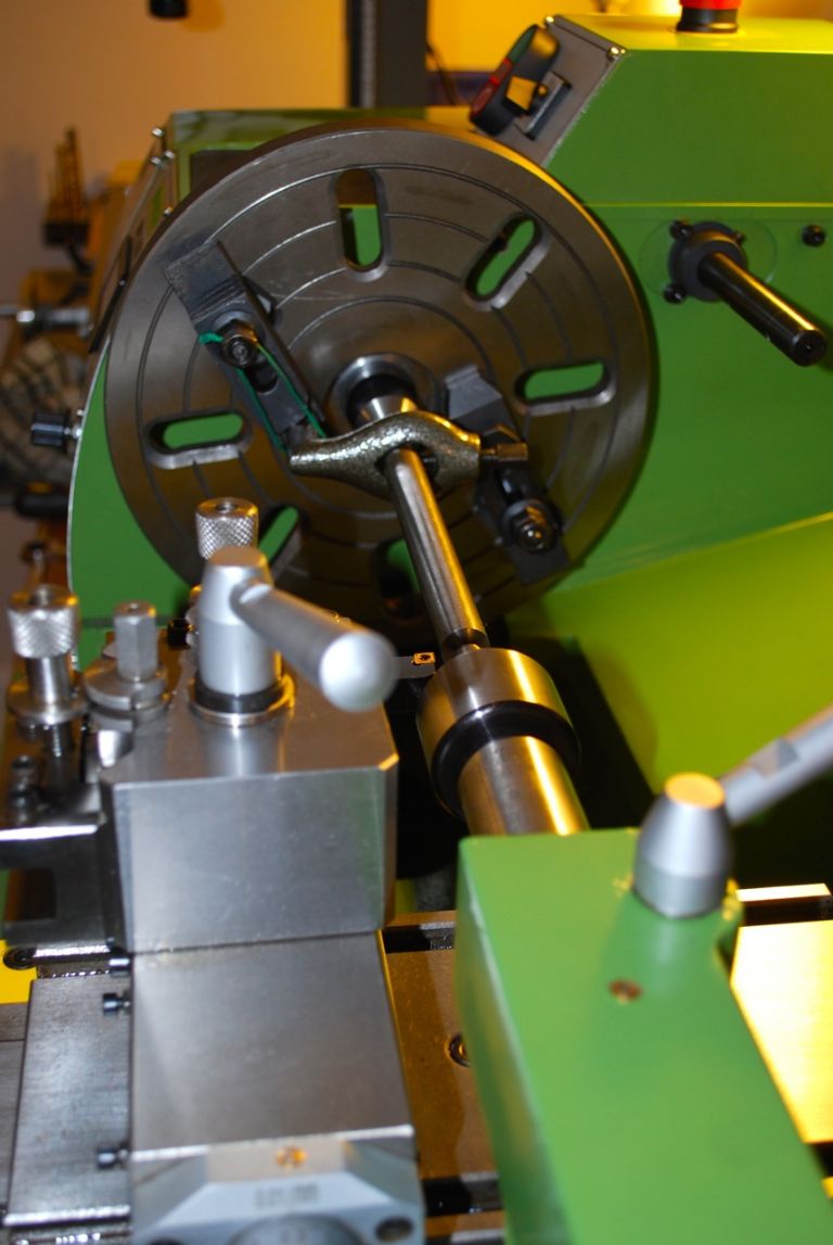
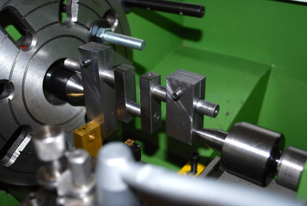
                I was stumped for a while in how to reach between the webs to skim the Crankpin when assembled between centres – in the end I ground a round nose on a piece of approx 1/8" tool steel and put into the tool holder on top of an existing tool, to my surprise it worked a treat and gave a great finish..

                Anyway some pics of progress along the way..

                Ready to start turning the larger diameter of the main shaft.

                220. turning the crankshaft..jpg

                The shaft reversed between centres to turn the smaller diameter.

                221. turning the crankshaft 2..jpg

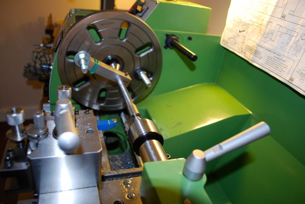
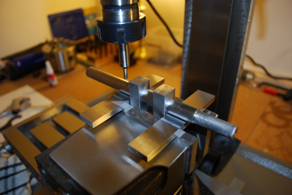
                Setting up to drill the Crankshaft Webs.

                223. setting up to drill the crankshaft webs.jpg

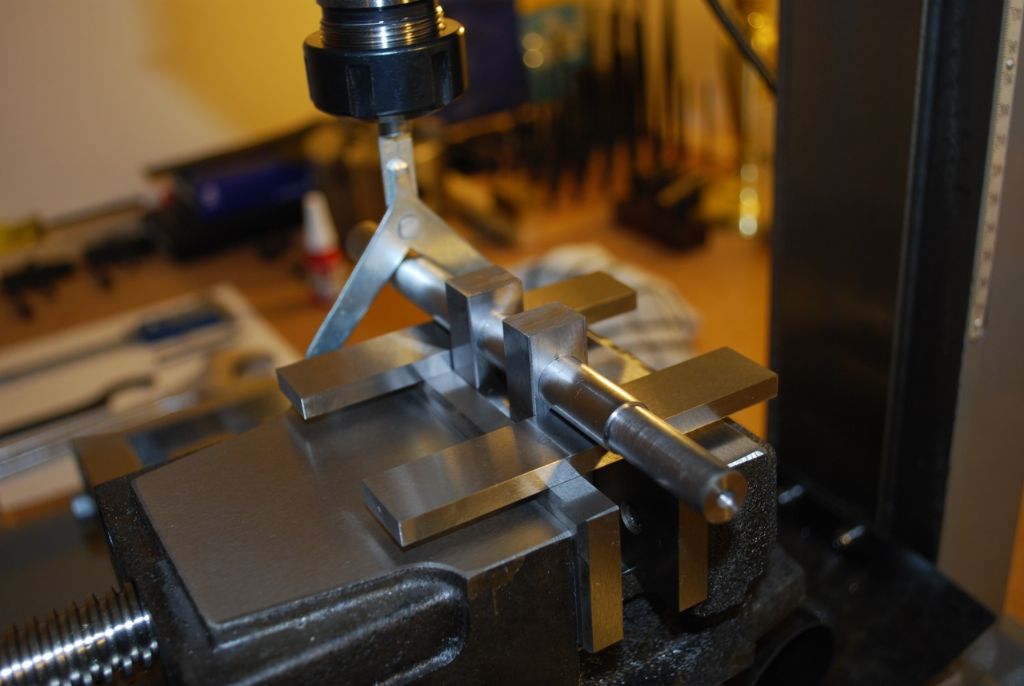
                Setting up to drill the Crankshaft Webs 2 with an edge finder. First time for me using this and was great.

                224. setting up to drill the crankshaft webs 2.jpg

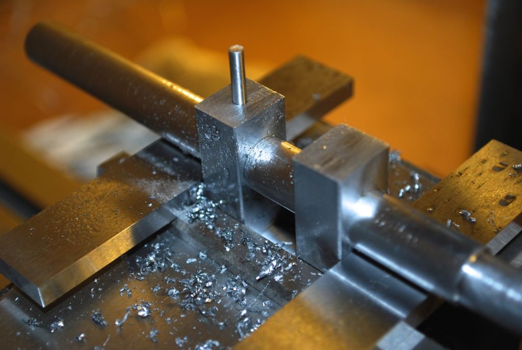
                The first of the 4 pins. I used 1/8" Silver Steel.

                225. starting to pin the crankshaft assembly.jpg

                Ready to start turning the Crankshaft Assembly.

                226. ready to turn the crankshaft assembly.jpg

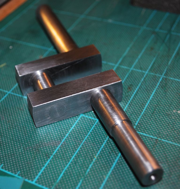
                The finished Crankshaft.

                227. the finished crankshaft..jpg

                Test fitting the Crankshaft in place. As a first attempt I'm quite pleased with it – and I've learned lots again through all the mistakes.. The fit seems very nice and it spins very nice and smooth..

                228. the crankshasft in place 1..jpg

                Cheers.

                Allan.


                Edited By Allan. on 31/03/2015 17:05:45

                Edited By Allan. on 31/03/2015 17:10:15

                #185353
                GarryC
                Participant
                  @garryc

                  Hi

                  I don't know if anyone is about today, Good Friday, I'm just about to clamp the Flywheel to the faceplate which I can remember was a bit fiddly last time and I'm wondering if there is any reason why I shouldn't do it in the 3 Jaw Chuck as I will be skimming it later when fixed on the crankshaft and between centres in the lathe (fixed using a grub screw and with a flat on the shaft)?

                  Thank for any advice.

                  Regards.

                  Allan.

                  Edited By Allan. on 03/04/2015 11:13:39

                  #185362
                  GarryC
                  Participant
                    @garryc

                    Sorry forget that – turns out my chuck is just slightly too small anyway. So faceplate it is..

                    Cheers.

                    Allan.

                    #185369
                    JasonB
                    Moderator
                      @jasonb

                      Should be able to get it in the 4 jaw which will also allow you to get the inside edge of the rim running true


                      J

                      Edited By JasonB on 03/04/2015 13:08:59

                      #185376
                      GarryC
                      Participant
                        @garryc

                        Thanks very much Jason, I'll give that a go now. The flywheel is only 1/4 inch diameter larger than Victoria's but it feels much heavier and so more awkward..

                        Have a good bank holiday..

                        Cheers.

                        Allan.

                        #185700
                        GarryC
                        Participant
                          @garryc

                          Just a quick update of what looks like nothing I suppose but I was a bit stuck for a while…

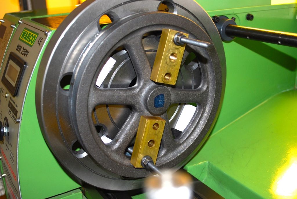
                          After failing to get the Flywheel centred close enough on the faceplate in the lathe (I just haven't the knack with setting up the faceplate yet) I did manage to get it in the 4 jaw but with really only 2 jaws holding and those not brilliantly so – tried a different approach this morning..

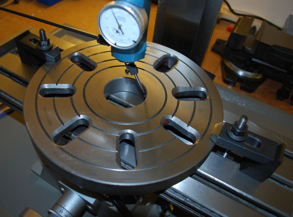
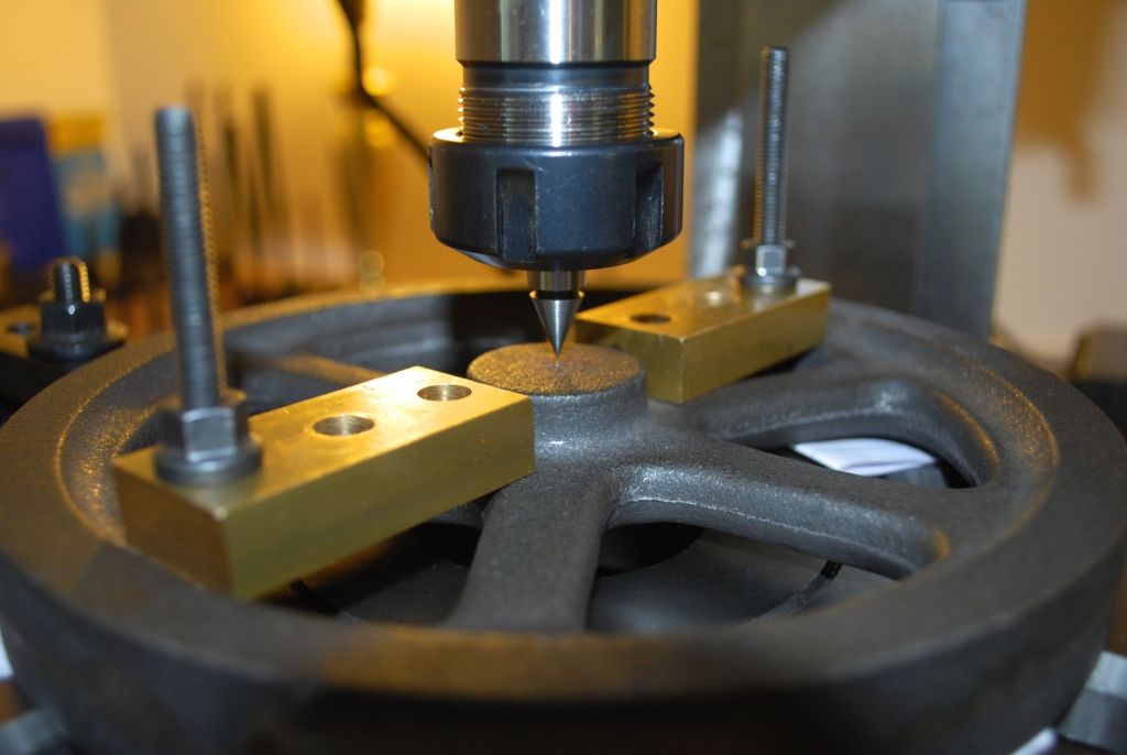
                          Thought I would get the faceplate off the lathe and centred on the Mill which I thought should make it easy to get the Flywheel clamped in place – so I took a few diameter readings of the boss (not machined and a bit rough) and used the average to mark its centre and centre punch.. The faceplate will get skimmed when on the Crankshaft between centres on the Lathe later.

                          Centering the Faceplate on the Mill.

                          229. centering the faceplate on the mill..jpg

                          The Flywheel finally centred and clamped on the faceplate.

                          230. centering the faceplate on the mill 2.jpg

                          The faceplate back on the lathe and flywheel casting spinning as true as poss. This method was just so much easier than trying to clamp when in place on the Lathe. Think I will always try this way first in future now.. I spent ages on and off trying while on the lathe and maybe 10 – 15 minutes to do it this way…..

                          231. the flywheel ready for machining in the lathe..jpg

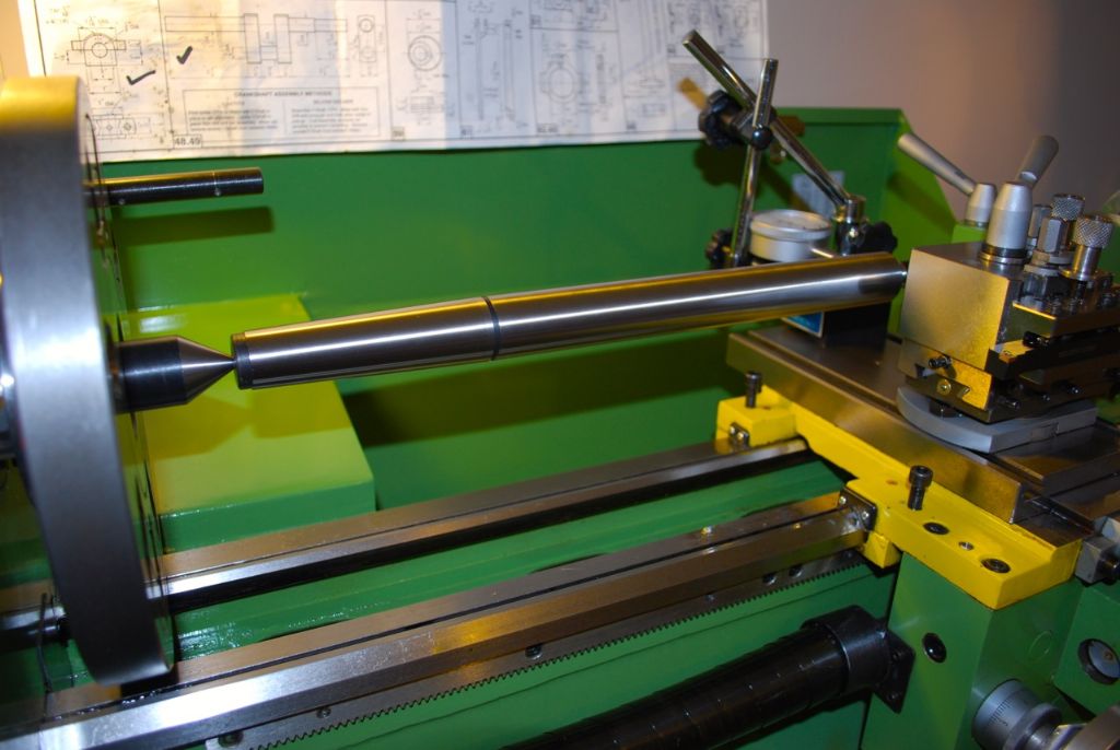
                          Setting the Tailstock with a Test Bar. Following my recent troubles with the tailstock offset it was good to be able to set it correctly. I had previously set it using the ruler between centres method – the test bar (12 inch) showed it to be out by just under 2 thou – I was surprised it was that close as it seemed a bit hit and miss with the ruler at the time.

                          232. using a test bar to set the tailstock..jpg

                          So no real progress on the Engine I guess but I get just as much satisfaction from continuing the learning process..

                          Hope it was of interest.

                          Regards.

                          Allan.


                          Edited By Allan. on 06/04/2015 12:13:46

                          #185920
                          GarryC
                          Participant
                            @garryc

                            Still edging forward very slowly with the flywheel..

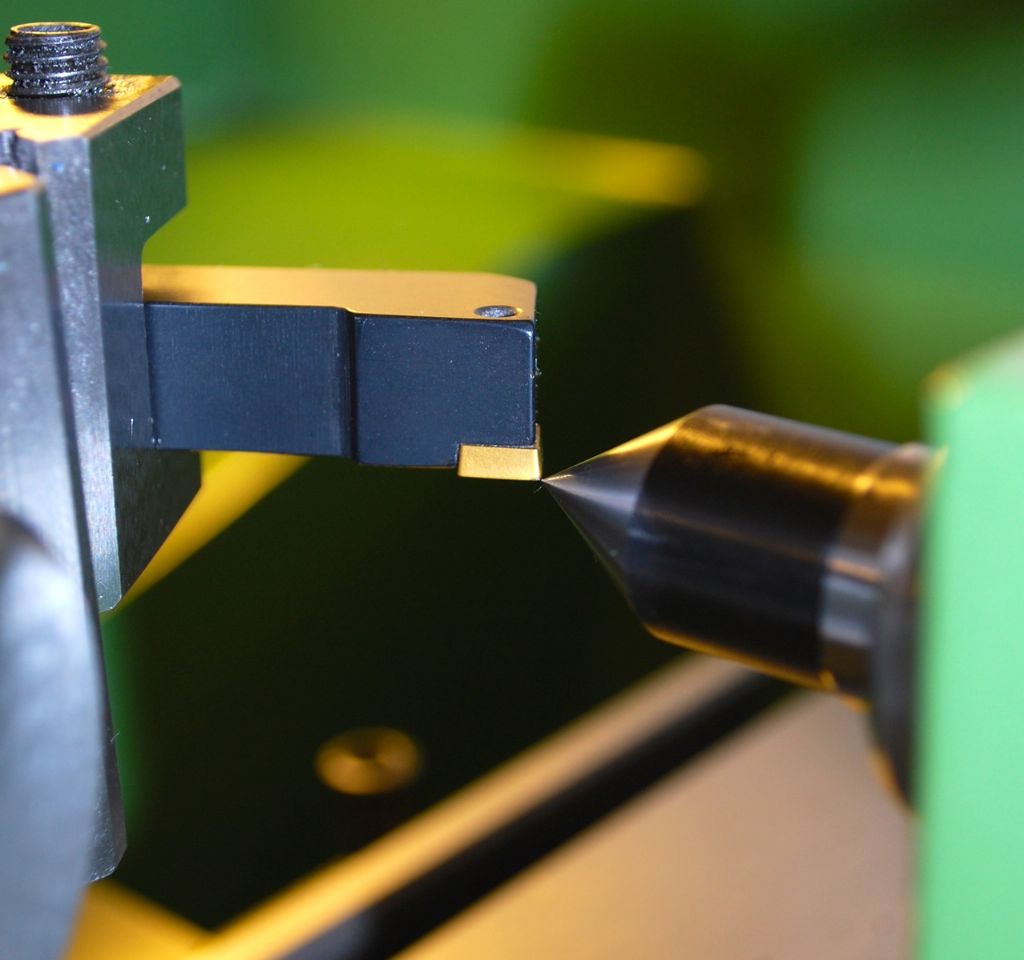
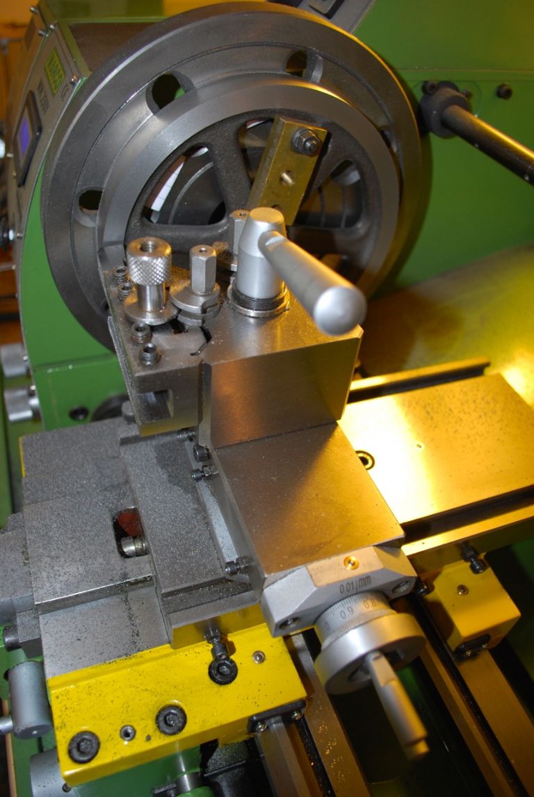
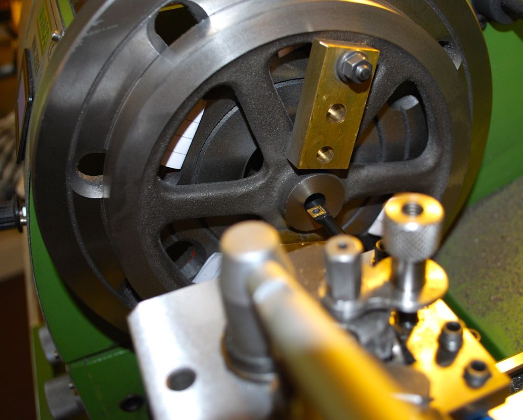
                            In order to get the tool to the outside of the flywheel rim I needed to use a right handed tool (hope thats the right way round – point facing the tailstock I mean) but the only one I had was a short 10mm size and with the necessary overhang it was flexing (and I was in trouble again). Then I remembered reading somewhere that it was ok to turn the tool upside down and reverse the lathe – so I did this with an ordinary left hand but larger 12mm tool and it worked perfectly, I used it this way round for the outside of the rim as well. Surprising how much difference the 2mm increase in size made and I had no problems once it was set.

                            The Flywheel Drawing

                            239. the flywheel drawing..jpg

                            Setting the upside-down tool to centre hight.

                            233. using the tool upside down for the flywheel.jpg

                            Turning the flywheel and remembering to leave it slightly oversize for skimming later when fixed to the Crankshaft. The new lathe will spin very slowly and I managed a not too bad finish. Maybe I can polish this up a bit as well later..

                            234. turning the flwheel..jpg

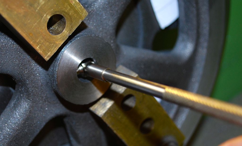
                            I used a small 6mm Boring Tool to do the bore.

                            235. using a small 6mm boring tool on the flywheel.jpg

                            Checking the Bore Size – gauge then put between the Micrometer. Managed to get a great push fit with the shaft using several passes of the Boring Tool at the same setting when close to size – until it was the nice push fit..

                            237. checking the flywheel bore size.jpg

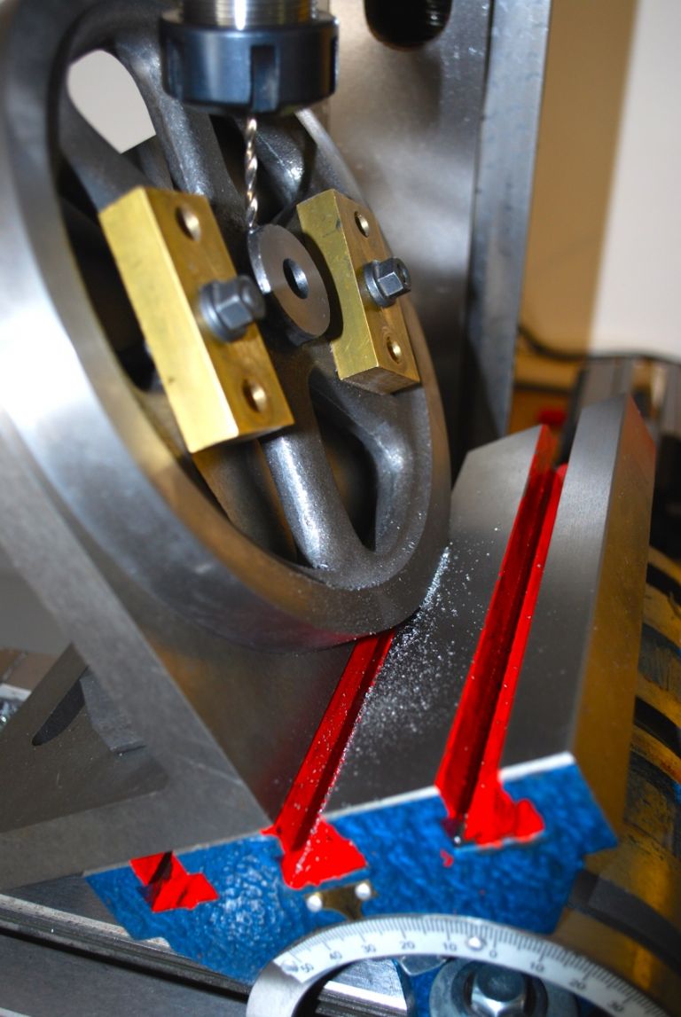
                            I measured the angle for the grubscrew directly off the drawing (made it 29 degrees) and set the angle table the same.

                            236. drilling the flwheel grubscrew hole.jpg

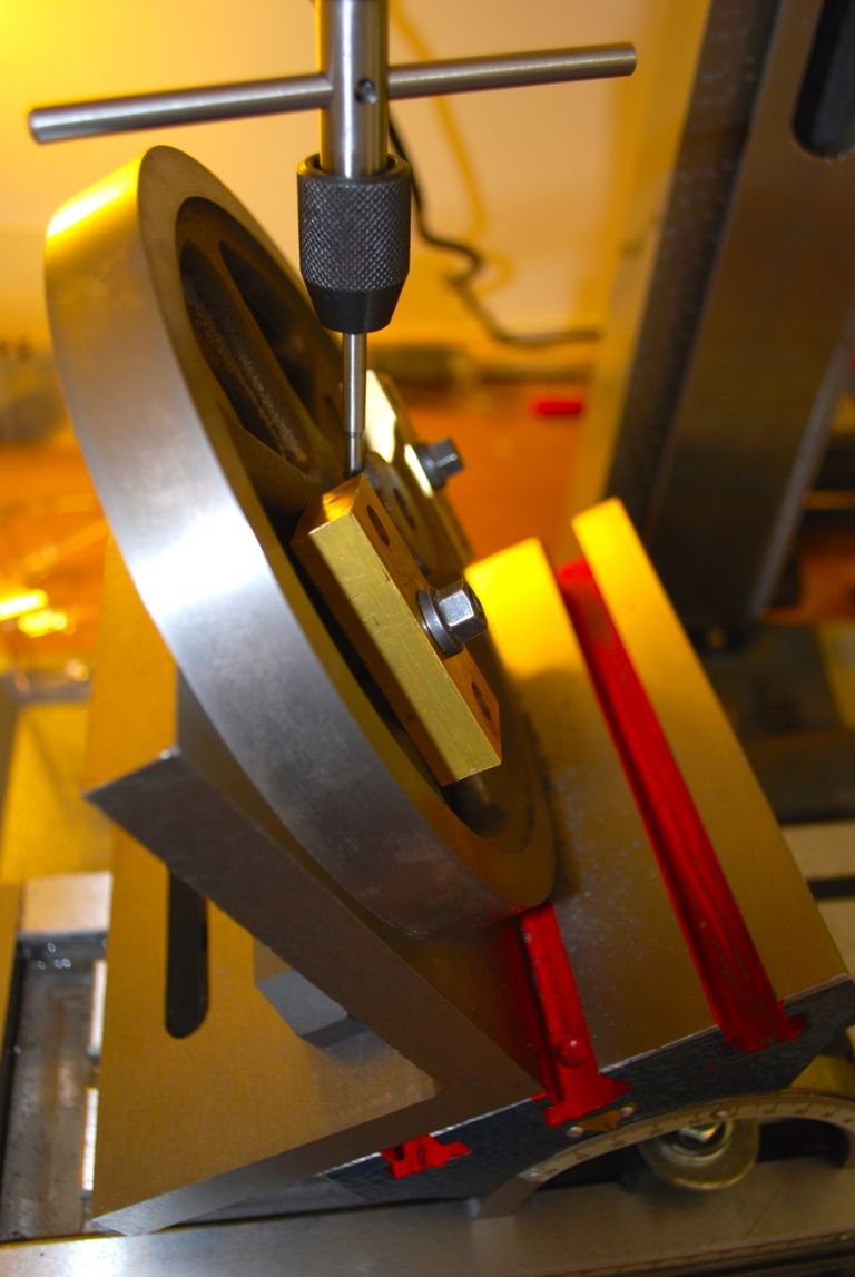
                            Then tapped 2BA.

                            238. tapping the flywheel for the grubscrew..jpg

                            I may have made a mistake by leaving the boss diameter size (both sides) to skim between centres later. Not tried anything like this before so will have to see how it goes. Hoping it will be ok with very light cuts and the shaft such a nice tight fit. I couldn't do it with the clamping pieces I had above. Need to get hold of some more stock for this kind of thing..

                            Next to put a small flat on the shaft for the 2BA grubsrew before giving it a skim between centres.

                            Cheers.

                            Allan.


                            Edited By Allan. on 09/04/2015 16:20:44

                            #185932
                            Jesse Hancock 1
                            Participant
                              @jessehancock1

                              Regarding G or C clamp usage: at a pinch I have filed a central V groove in the static end (Anvil?) 90 degrees to the frame and opposite the centre of the ball and swivel, which I have then used to hold a similar knife edge as you Allan.wink 2

                              However beware G clamps are made of malleable material which can buckle sideways or the jaws can open if too much grunt is used on the tommy bar.disgust

                              I know because I used to get the job of straightening them out once they were distorted by our gorillas.angry 2

                              #186021
                              GarryC
                              Participant
                                @garryc

                                Had a great couple of hours this morning finishing the Flywheel. I didn't know what to expect when I tried spinning the crankshaft assembly on the Lathe – and was amazed to see that the outer and side rims were running almost perfectly, had to look hard to see any deflection. Its not perfect though as there is some radial movement of the inside rim (and spokes), down to me not setting it up correctly initially no doubt. It seems like something of a 'dark arts' do in getting it centred to start with. If anyone has any tips I would love to hear them. It's good enough for me though at the moment and I've come away with a better understanding of some useful basic things again, and a lot of enjoyment!

                                Skimming the Crankshaft assembly – it only needed the lightest skim. I put a small flat on the shaft using the Mill for the grubscrew and didn't get any slipping of the Flywheel.( I did tie the throw plate to the driving bolt beforehand).

                                240. skimming the flywheel on the crankshaft 1..jpg

                                The Flywheel in place. Really chuffed when I spun it by hand, completely smooth and silent. The Webs are a nice snug fit between the bearings..

                                241. the flywheel in place..jpg

                                Cheers.

                                Allan.

                                #186023
                                JasonB
                                Moderator
                                  @jasonb

                                  Rather than mark out the centre of the hub and set that to run true I prefer to set the inside of the rim to run as true as possible as its harder to alter than than skim the hub. I also like to do this with the 4-jaw so you can make fine adjustments while rotating by hand on the lathe

                                  #186030
                                  GarryC
                                  Participant
                                    @garryc

                                    Thanks Jason, after just working through it I can see how that makes perfect sense.I should have persevered more with the 4 Jaw when I tried and crucially used the inner rim for setting.. Definitely the way I'll try next time around..

                                    Cheers.

                                    Allan.

                                    #186040
                                    roy entwistle
                                    Participant
                                      @royentwistle24699

                                      Allen When using a 4 jaw chuck it is easier if you use two chuck keys on opposite jaws

                                      Roy

                                      #186041
                                      JasonB
                                      Moderator
                                        @jasonb

                                        I've never managed to get the 2 key method to work either on my previous Emco or the current Warco, the "box" like heads on these lathes mean you can't get a 1/4 turn of the chuck key without it hitting the head unless you have a very short tommybar which stops you getting it tight.

                                        J

                                        #186049
                                        GarryC
                                        Participant
                                          @garryc


                                          Thanks Roy, it is a bit tight with the chuck key as Jason says, hope one day to have a full size lathe!

                                          I'm gradually getting more comfortable with the 4 jaw chuck and recently watched a great youtube video on using the DTI, it was one of the'Toms Techniques' set which I found brilliant and after watching a good few times has finally sunk in and I have no problem and even enjoy using it now. Trouble with the flywheel though of course is you need to set the casting up with no surfaces to be able to use a DTI, at least I assume thats right as when I tried mine it jumped around all over the place on the rough casting. Something will click eventually with them I hope!

                                          I also now use Toms 'formula' for working out what machining speeds to use and this feels better all round, although I can't reach some of the higher speeds recommended. Some of the early problems I had, especially drilling, were down to my ignorance of such things – my machines all seem to run much better now (Its taken far too long for me to get that right).

                                          Cheers

                                          Allan.

                                          Edited By Allan. on 10/04/2015 18:52:39

                                          #186052
                                          JasonB
                                          Moderator
                                            @jasonb

                                            Just put the blunt end of a tool in the tool post or I prefer a sharpened pencil and with it a little way from the casting rotate by hand and your eye will soon show you where the gap is large or small. Adjust until you get a good average, remember the casting may be a bit oval or egg shaped so it may never clock perfectly true

                                            #186053
                                            ChrisH
                                            Participant
                                              @chrish

                                              Hi Allen, I am also a fan of Tom's and his advice has helped me a lot. I also use his formula for getting machining speeds but like you my available speeds don't go that high, in theory to 1600rpm on the lathe and 2150 on the mill.

                                              The YouTube video on using the DTI on Tom's Techniques, which one was that? I think I am confusing myself as when I read your last post I convinced myself it was a video of using a 4 jaw chuck with the DTI, now I am not so sure! Certainly his use's of DTI and DRO's have been eye-openers for me, mainly because I don't have that experience.

                                              Chris

                                              #186055
                                              ChrisH
                                              Participant
                                                @chrish

                                                I have just been getting some little castings reading for turning and holding in a lathe collet chuck by turning down the chucking piece of the castings to a diameter that will fit one of the collets I have. I found I could get quite an accurate and acceptable set-up by using a 2mm parting tool in the toolholder, turning the lathe chuck by hand (power off, drive disengaged) and eye-balling the tool-to-work gap, good enough to be able to turn the chucking piece anyway.  The parting tool allowed an idea of the casting alignment to be gained by comparing the side of the casting to the side of the parting tool whilst the end of the tool (the business end as it were) showed how far the chucking piece was off being centred.

                                                Chris

                                                Edited By ChrisH on 10/04/2015 20:15:04

                                                #186058
                                                Peter Tucker
                                                Participant
                                                  @petertucker86088

                                                  To use the two key method for centring a four jaw chuck you need to make knurled knob like chuck keys which facilitate rapid movement of the work, when the work is on centre final tightening needs to be done with the standard tommybar type key.
                                                  Hope this helps.
                                                  Peter.

                                                  #186091
                                                  GarryC
                                                  Participant
                                                    @garryc

                                                    Hi Jason

                                                    So that's how you do it! Big big thanks for that – now I know how to go about it. Made my day that has having something to use now! Thank you. ( I had convinced myself last night that I could maybe use a pair of dividers in the tailstock drill chuck, it didn't work of course when I tried it this morning!)

                                                    Hi Chris

                                                    Thanks as well, I found that very interesting, you seem to be using the same method as Jason..

                                                    Sorry for the confusion about the video – you are right I was meaning 'how to set the 4 jaw with the DTI' but the video I settled on was not one of 'Tom's Techniques' but it was another Tom – **LINK** I watched it several times and even wrote down the steps, it seems straight forward now but not at the time. It was a eureka moment when it finally sunk in, felt like a blindfold being taken off! I have an idea yours and Jason's post will be another little milestone for me…

                                                    Hi Peter

                                                    Thanks, yes that would work on the little lathe. So many useful things to make given the time!

                                                    Great start to the day.

                                                    Cheers

                                                    Allan.

                                                    #186101
                                                    ChrisH
                                                    Participant
                                                      @chrish

                                                      Hi Allen, thanks for the link, found that video very instructive. The method was very similar to the way I do it but far more logical and far quicker – look forward to trying it for real!

                                                      Chris

                                                    Viewing 25 posts - 26 through 50 (of 602 total)
                                                    • Please log in to reply to this topic. Registering is free and easy using the links on the menu at the top of this page.

                                                    Advert

                                                    Latest Replies

                                                    Viewing 25 topics - 1 through 25 (of 25 total)
                                                    Viewing 25 topics - 1 through 25 (of 25 total)

                                                    View full reply list.

                                                    Advert

                                                    Newsletter Sign-up