My Little Donkey

Advert

My Little Donkey

Home Forums Stationary engines My Little Donkey

Viewing 14 posts - 1 through 14 (of 14 total)
  • Author
    Posts
  • #619501
    JasonB
    Moderator
      @jasonb

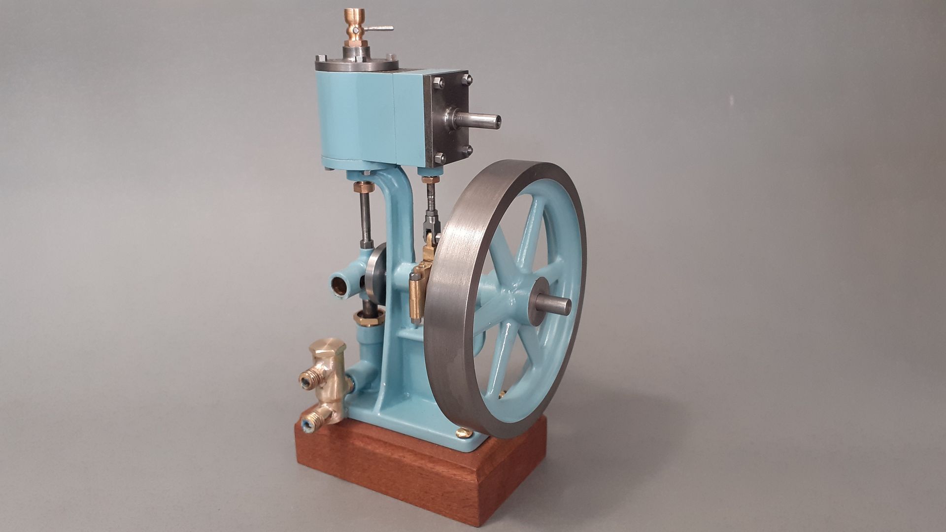
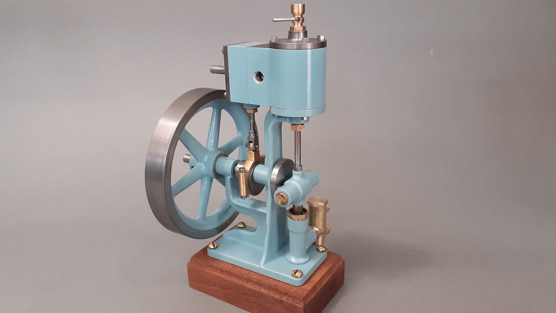
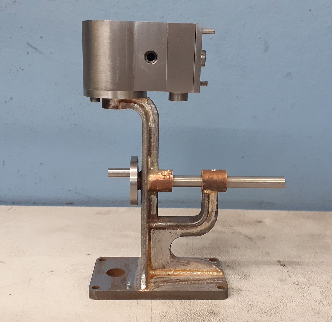
      No not the must have Christmas gift that all the kids want this year but my recreation of a Bassett-Lowke Donkey Pump from the 20-30s.

      All either fabricated or cut from the solid it's the same approx size as the original but my design is in metric so 16mm bore x 15mm stroke and an 80mm flywheel.

      Seems to run quite well and my first engine with a scotch yoke so that's something else that can be ticked off the list.

      Just needs a bit of house training now.


      Edited By JasonB on 02/11/2022 18:45:09

      Advert
      #3515
      JasonB
      Moderator
        @jasonb
        #619502
        Rex Hanman
        Participant
          @rexhanman57403

          That's nice!

          #619503
          Michael Gilligan
          Participant
            @michaelgilligan61133

            Very stylish [Duck-egg Blue and Brown]

            MichaelG.

            .

            P.S. __ It might have potential as a Die-Filer with suds !

            #619523
            Michael Gilligan
            Participant
              @michaelgilligan61133

              Please forgive the hi-jack, Jason … but I think you might like this pretty little Beetle:

              .

              .
              MichaelG.
              #619526
              Nigel Graham 2
              Participant
                @nigelgraham2

                Fine work! It's good to see some of these old model designs given a new airing!

                #619559
                JasonB
                Moderator
                  @jasonb

                  Thanks for the interest.

                  Michael, I have watch several of her videos including the bug which is quite a beast under the skin and a bit of a handful.

                  #619576
                  Mike Poole
                  Participant
                    @mikepoole82104

                    524e5644-9fd1-49f2-8d8a-fc16e16b8b1f.jpegA friend of mine hand painted this bug for his son, the paintwork is stunning, 9 coats were applied but the old joke is 8 get rubbed off. No scooby engine in this one though. Meanwhile back on topic, another lovely job Jason and an interesting twist with the Scotch Yoke.

                    Mike

                    #619597
                    JasonB
                    Moderator
                      @jasonb

                      A few people have asked for some more details about building this one, I won't do a bit by bit build description but will try to cover the main parts subject to what photos I took

                      The frame seemed the most logical place to start as that was the most complex so any deviations from design that may result could be gotten out of the way and the design of other parts altered to suit rather than having to remake or modify them, In the end that was not really needed. I tend to design my fabrications as a single 3D part and then pull off the details of the various sketches and extrusions that make up the part as individual pieces.

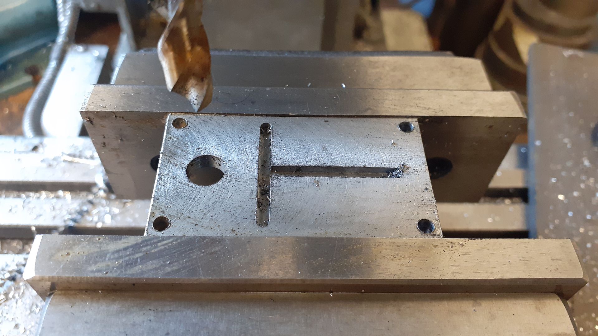
                      Starting from the bottom a piece of 5mm sheet was thinned down to 4mm, taking equal amounts off both sides, then milled to the required length and width. To help locate the other components some 2.5mm x 1mm deep slots were milled and the holes for the mounting screws and pump ram body drilled

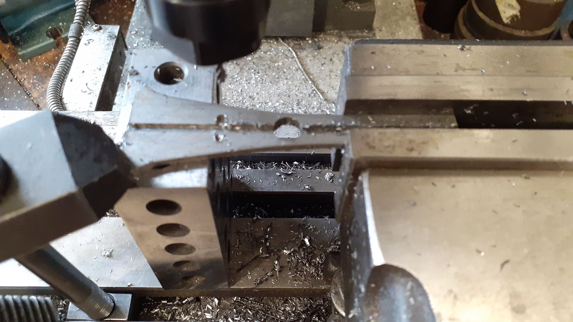
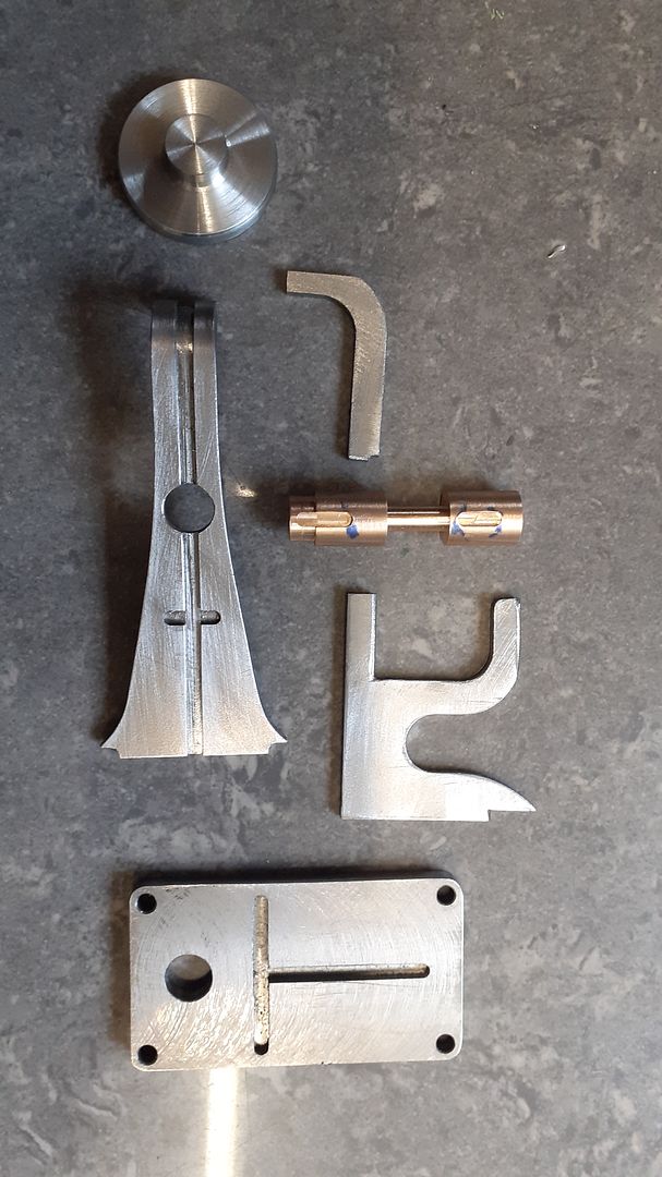
                      Although they would not be too hard to shape by hand I made use of the CNC to cut the shape of the 3 pieces of 2.5mm steel that make up the majority of the frame. Once cut I put some more slots in on the manual mill and also squared up the internal fillets left by the 3mm milling cutter on the CNC with a file so they would drop into the slots. Bending was done after the machining was complete, nothing fancy just a piece of round rod in the bench vice to give the desired radius and bent by hand.

                      The cylinder mounting flange was just simple turning and I left it over length and over diameter so it could be finish machined after assembly. A piece of Culphos had a spigot turned on one end to locate in a hole in the vertical leg of the frame and was thinned in the middle. This thinner area will get milled away but it helps to keep the two bearing pieces lined up if they are soldered as one piece.

                      The parts all slotted together quite well and I only used one loop of soft iron wire to hold a couple of bits together though I did decide to solder the cylinder flange on as a second heating.

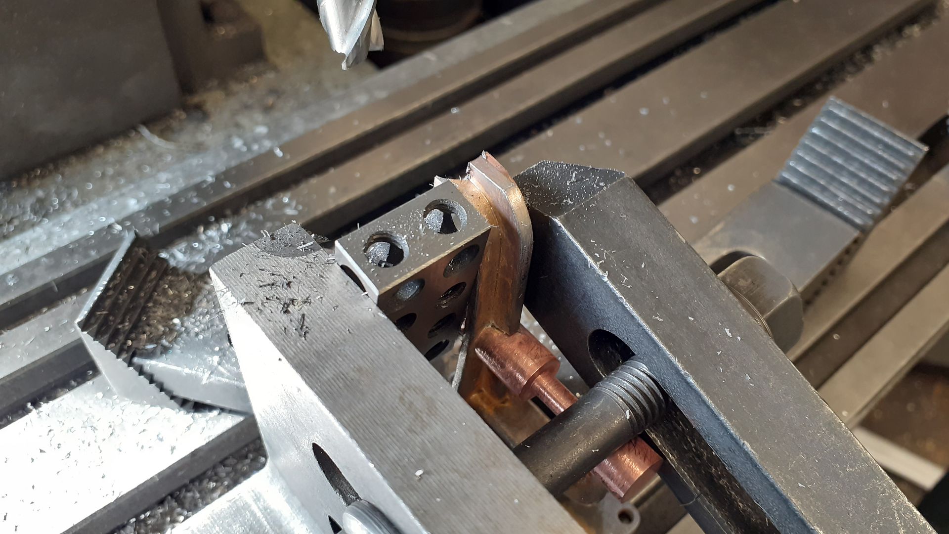
                      Here is the rest of the soldered frame having the location radius for the flange machined as it was easier to locate at that stage than when all the bits were separate. The main clamping is down to the mill table but I added an angle plate and a clamp to reduce the chance of any chatter while plunge cutting to form the radius.

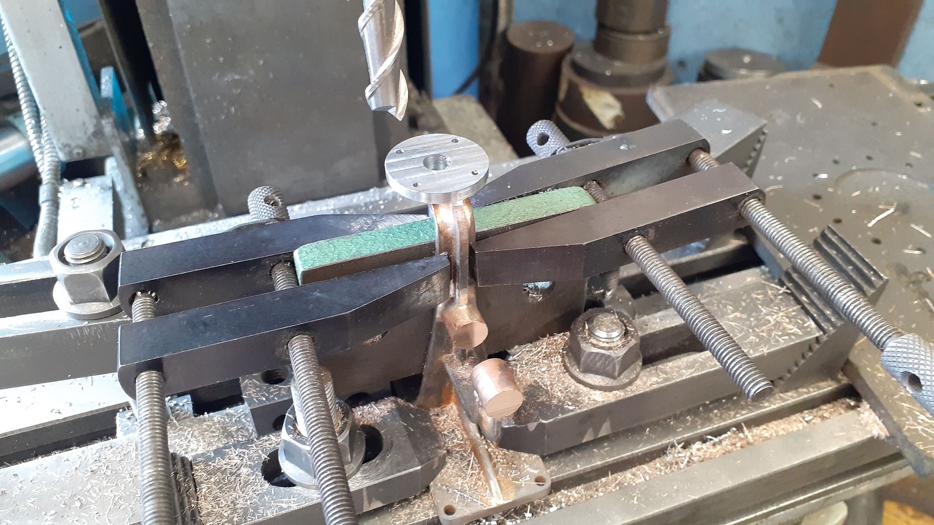
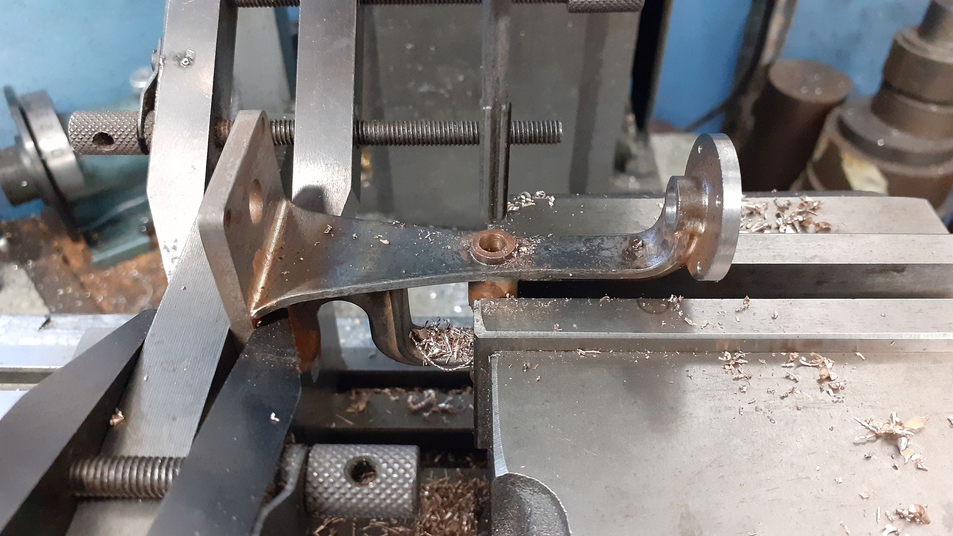
                      After soldering on the flange a similar setup was used so that the OD of the flange could be "turned" concentric to the hole for the pump ram body using the boring head and the thickness brought down to finish size ensuring it was at right angles to the vertical axis of the engine and the hole for the piston rod gland drilled and reamed true to that. Cylinder stud holes were the last things to do to the flange. I also used a long series non ferrous specific milling cutter to face the ends of the bearings to length.

                      The final job on the frame was to set it up on it's back so that the two bearings could be drilled 4.8mm and then reamed out to 5mm diameter.

                      #619851
                      JasonB
                      Moderator
                        @jasonb

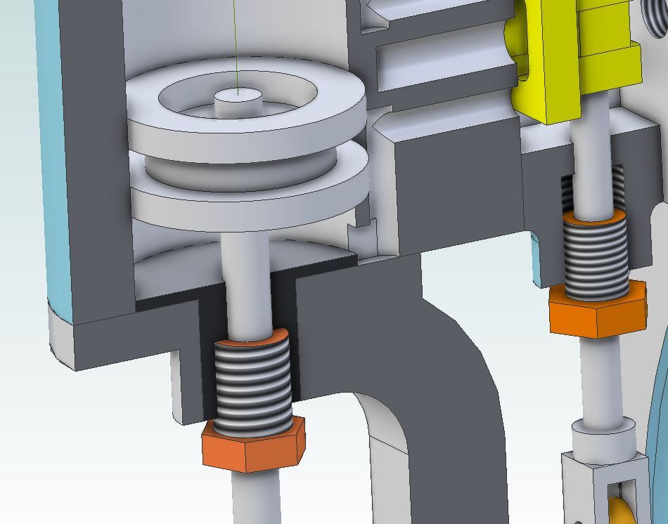
                        Those that have Been paying attention will no doubt have noticed that the hole in the cylinder mounting flange for the piston rod is quite large and that there is no short spigot to locate the bore of the cylinder. The reasons for this are 1. it would be tricky to counterbore and thread a larger hole than the 3mm piston rod required to take the gland from the underside. 2. forming the spigot to locate th ecylinder would also be tricky though could be done by mounting the frame on the rotary table or using a boring & facing head if I had one.

                        To overcome these two issues I turned up a separate piece from Cast Iron bar and loctited it into place, this section of the drawing should show how it works.

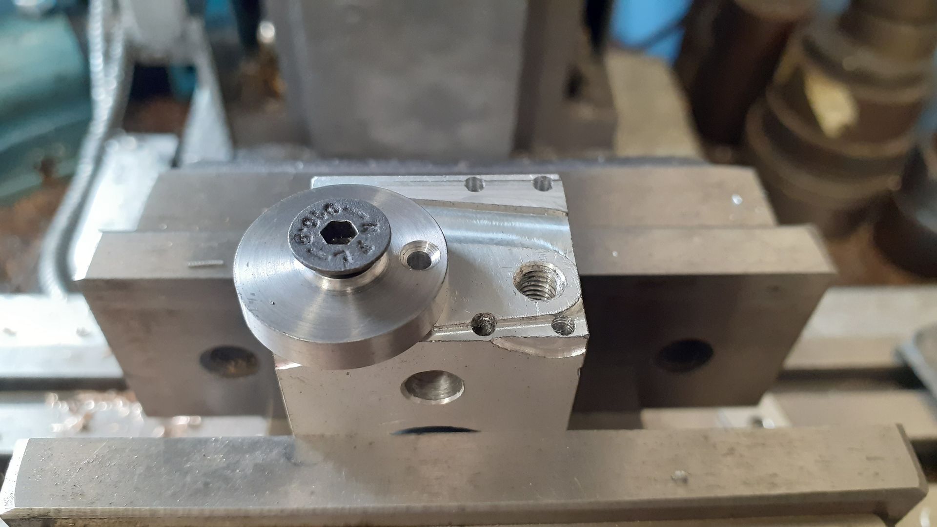
                        The crankshaft is made up from a length of 5mm PGMS with the over thick crank disc loctited into place and a silver steel crank pin retained with a CSK screw. Here you can see the turned and reamed crank disc has been screwed to a scrap block, its ctr location found and then offset to drill and CSK the hole for the pin retaining screw. After that it was loctited to the shaft and once set the shaft was held in a collet and the disc faced to the required thickness which ensures the face is perpendicular to the shafts axis.

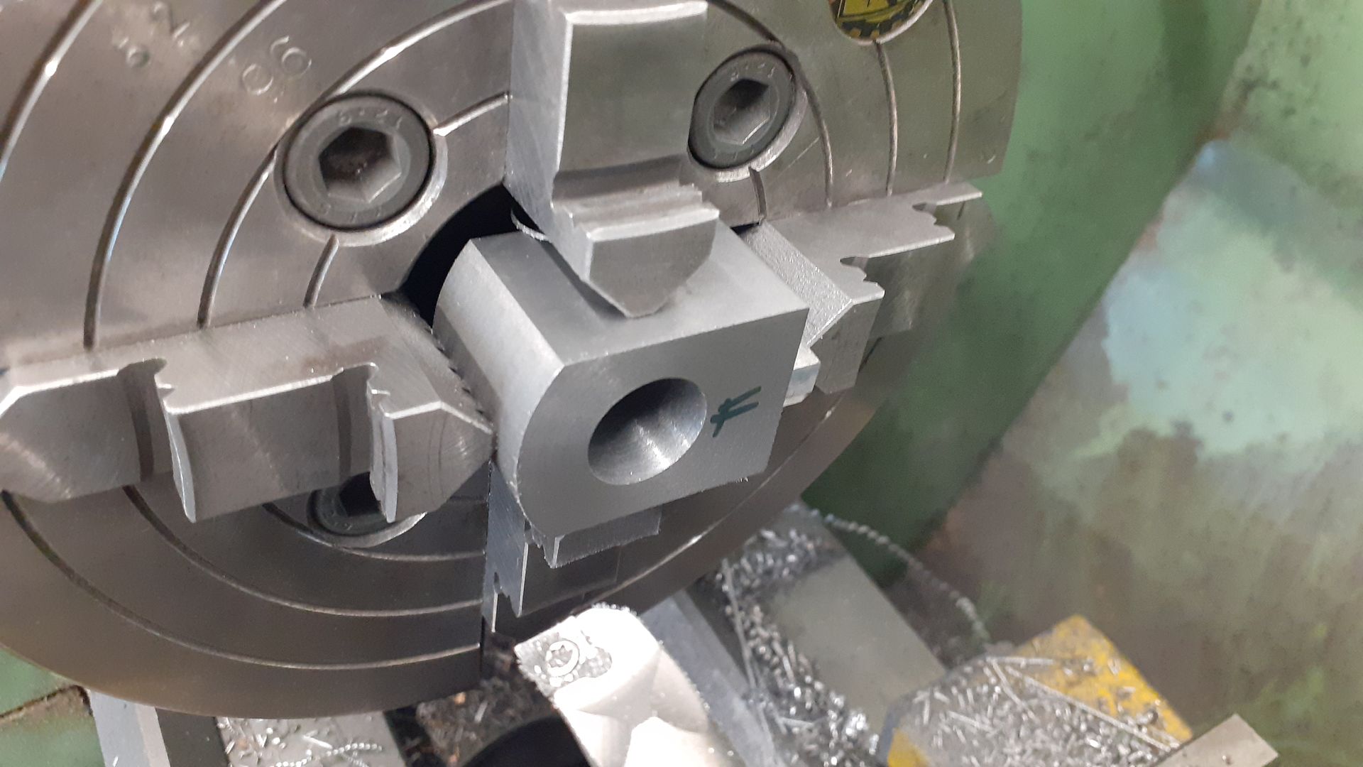
                        A quick circle drawn onto the 3D model of the cylinder showed that it could be carved out of apiece of 40mm dia CI bar so a piece was sawn off and then faced both ends leaving it a little over length. I then milled down 3 sides, one to form the port face and the other two to make it easier to hold in the 4-jaw before ctr drilling to mark the location of the bore. With the block back in the 4-jaw and the ctr drilled hole set to run true the cylinder could be bored and the end faced off true to the bore while bringing the cylinder to final length.

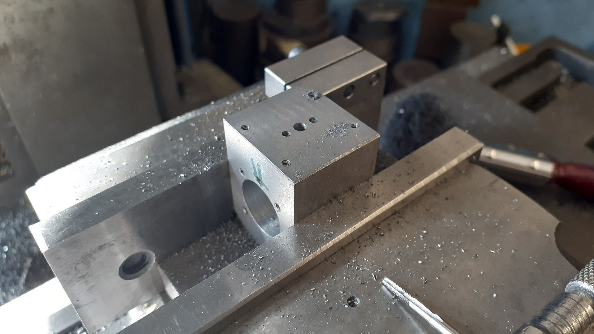
                        Moving back to the mill with the port face upwards in the vice the ctr was found and the inlet and exhaust port holes drilled as well as drilling and tapping for the valve chest studs.

                        It was then a case of standing the cylinder on either end to drill the steam passage down to the port and mill a slot to connect that drilling to the end of the bore. The cover stud holes were also drilled and tapped M2 on their PCD at the same set up. Vice stop in use here to save having to re find the bores ctr when it is turned up the other way.

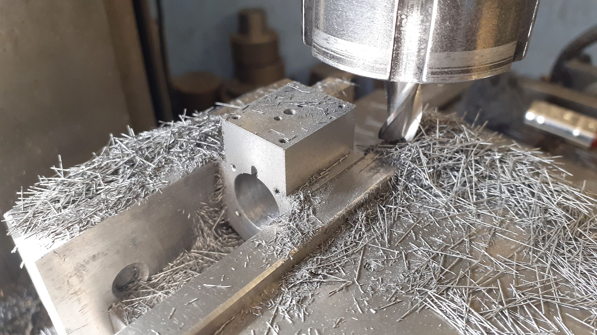
                        I could have used the CHC to profile the cylinder with it stood vertically be decided on the manual method of firstly reducing the width either side to that required to match the valve chest using full height passes the swarf was coming of in nice long ribbons.

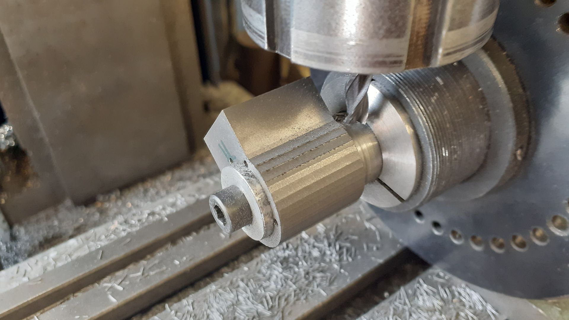
                        The last bit of machining on the cylinder was done with it mounted on a mandrel and held in the spin indexer to make a series of cuts to form the "rounded" part of the cylinder. After machining these were just blended into one another by filing.

                        #619904
                        Dave Wootton
                        Participant
                          @davewootton

                          Another lovely little engine Jason, something a bit different too.

                          Just wanted to sat thanks for posting this, your top hat idea for locating the cylinder and forming the gland register is brilliant. I've been puzzling for a while over a end cover for a small victorian horizontal engine belonging to a friend, nicely made with a studded gland, unfortunately completely butchered at a later date ( I assume to fit o ring seals) . This will enable an invisible repair to be made easily and maintain concentricity. Once again why didn't I think of this!

                          Are you going to publish drawings for this, would make a great in between job, I like to do little projects when bogged down on the major ones.

                          Dave

                          #620013
                          JasonB
                          Moderator
                            @jasonb

                            Thanks Dave and good to know you can put the separate gland method to good use, I've actually used it on a couple of other engines both where long trunk guides would have made access difficult from the gland end.

                            I been asked by a couple of other people about drawings so I'll probably do a set but won't be for a few weeks at least.

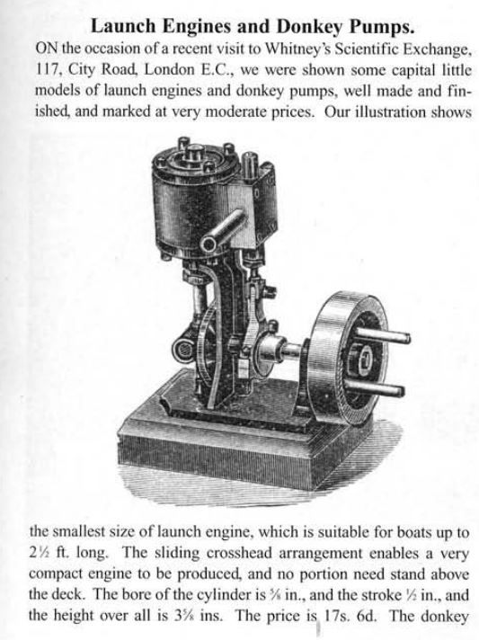
                            I came across this a couple of days ago which would be another option for those not wanting to do the pump part and the solid flywheel would be easy from a slice of CI bar.

                            Edited By JasonB on 06/11/2022 20:34:57

                            #621831
                            JasonB
                            Moderator
                              @jasonb

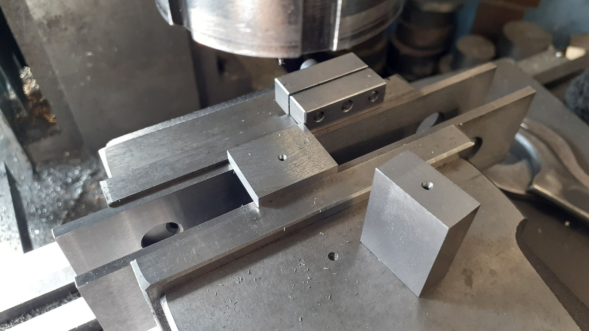
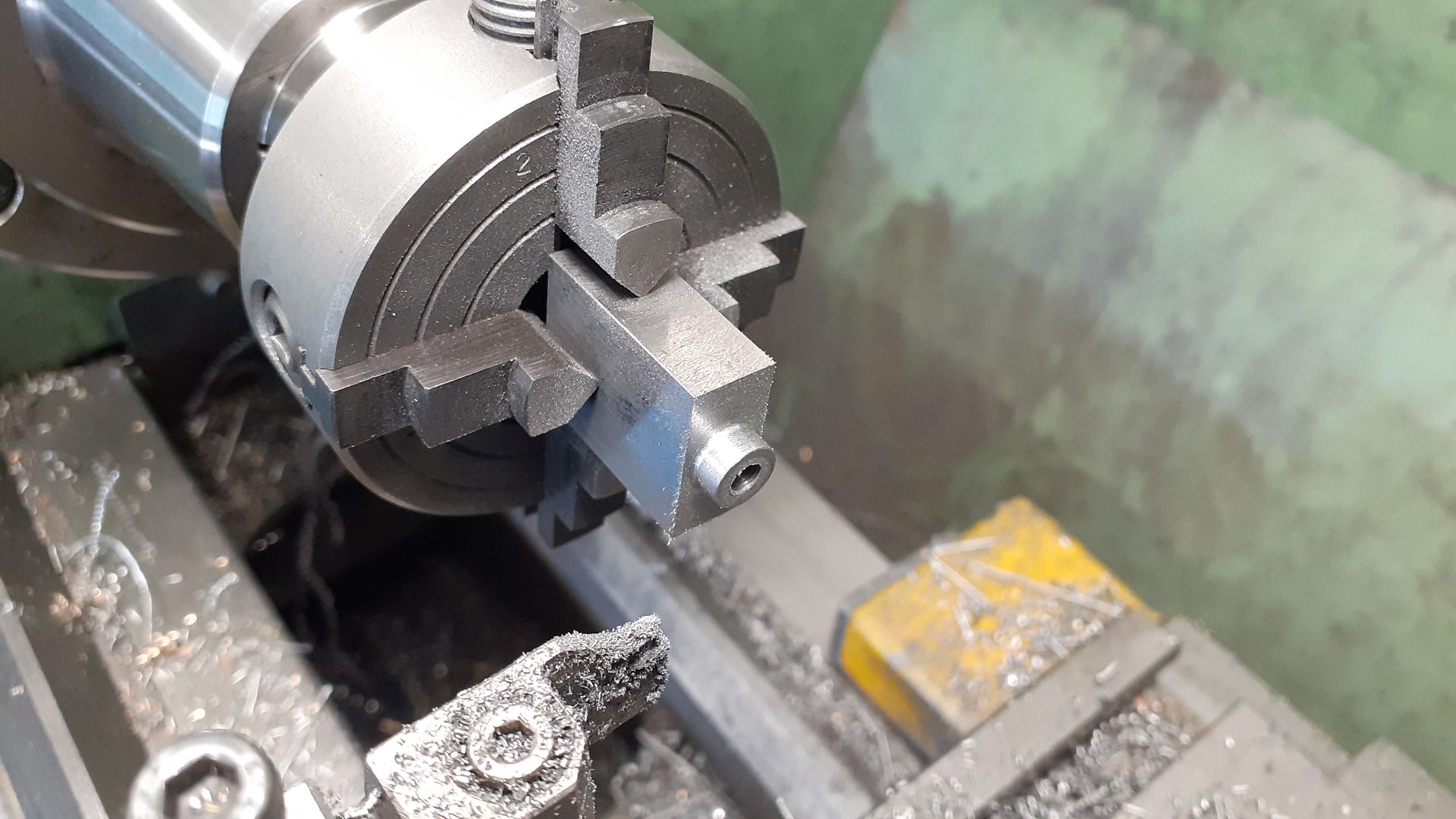
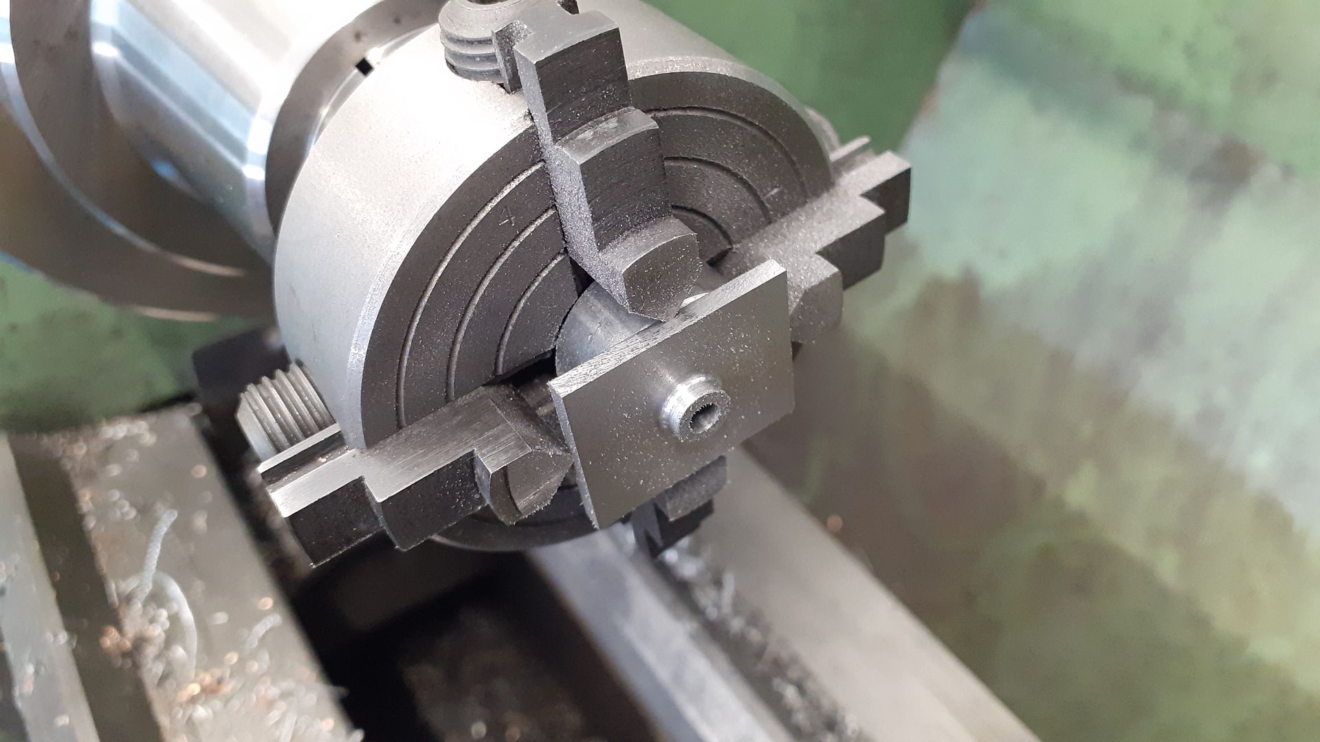
                              Two blocks of cast iron were milled up to the overall sizes needed for the valve chest & cover and a couple of ctr drill holes added to aid clocking them in the 4-jaw.

                              First the valve chest was turned to form the spigot for the gland, final cuts were done with a 1mm radius tool to leave a small fillet where the spigot meets the chest.

                              The same methods were used on the chest cover to form the boss where in inlet pipe screws in, this was tapped M4 x 0.5 metric fine. I've taken to using my old Unimat 3 four jaw chuck on a 1/2" parallel arbor for smaller items as that can be slipped into the 5C chuck and saves having to change to the larger 4-jaw.

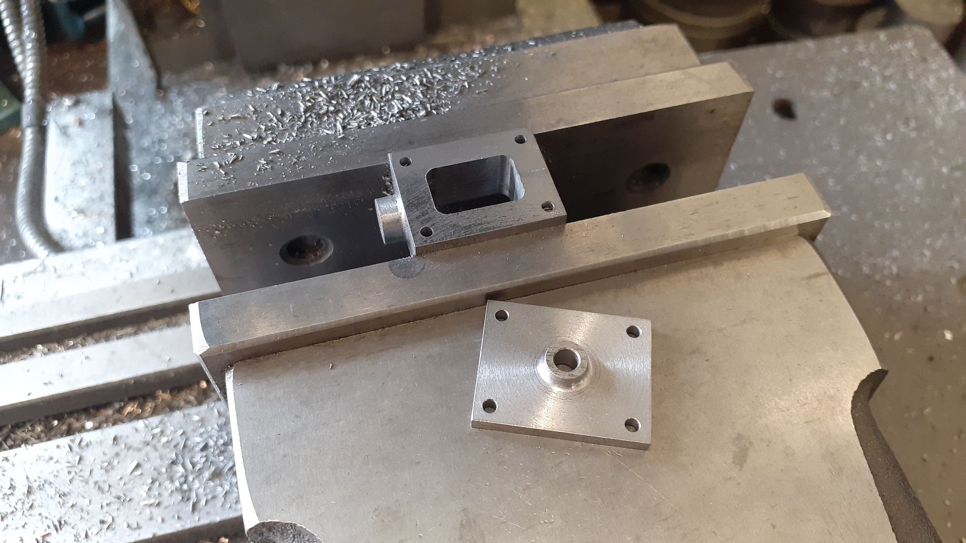
                              Then back into the mill vice to drill the stud clearance holes and mill out the cavity in the chest which was roughed out with a couple of drill holes then a few laps around the edge with a 4mm dia cutter to form the rectangular cavity.

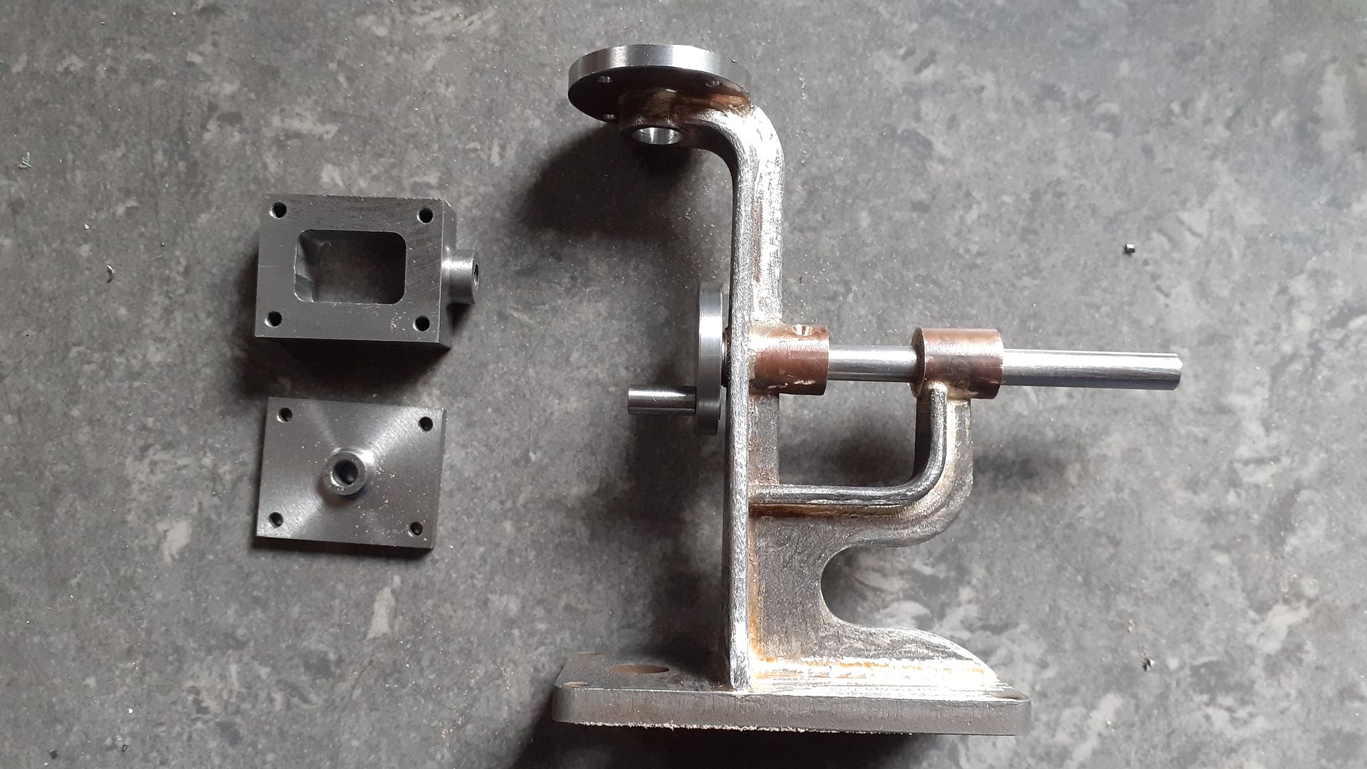
                              Progress so far

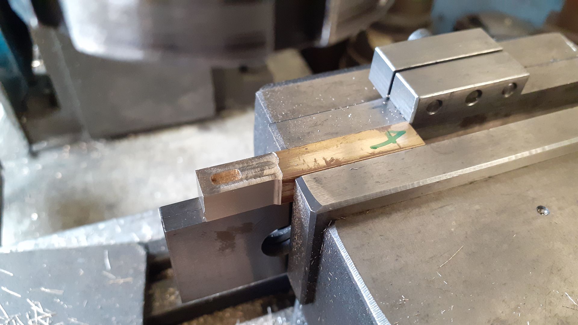
                              The valve was machined on the end of some 8mm square brass bar, first the cavity

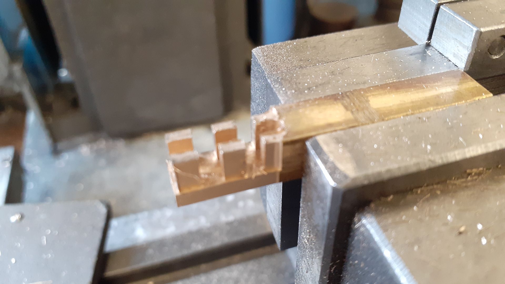
                              Then the slots for the nut and rod

                              #621832
                              Taf_Pembs
                              Participant
                                @taf_pembs

                                Like that Jason, nice one thumbs up

                              Viewing 14 posts - 1 through 14 (of 14 total)
                              • Please log in to reply to this topic. Registering is free and easy using the links on the menu at the top of this page.

                              Advert

                              Latest Replies

                              Home Forums Stationary engines Topics

                              Viewing 25 topics - 1 through 25 (of 25 total)
                              Viewing 25 topics - 1 through 25 (of 25 total)

                              View full reply list.

                              Advert

                              Newsletter Sign-up