Musings on where to put DRO displays

Advert

Musings on where to put DRO displays

Home Forums Workshop Techniques Musings on where to put DRO displays

Viewing 13 posts - 1 through 13 (of 13 total)
  • Author
    Posts
  • #85803
    Ian P
    Participant
      @ianp

      I recently fitted economy DRO scales (igaging) to my Emco milling machine. These work on the same system as the cheap Chinese calipers but have the digital display at the end of a 1m cable.

      I have only done the X and Y axis (mounting both took about 2 hours) and I then mounted the displays on the head of the machine. facing the front.

      Whilst the DRO works as expected, when I used them in ernest on the first job I found the machining less instinctive and slightly more 'stressfull' than normal. When I analysed the problem I realised that when turning a handwheel to approach a particular reading my gaze was at the display and I had no sight of the job, or probably more especially, my hand on the handwheel.

      I think visual feedback from the graduated collars and being able to see my own hand movement combine to made the non electronic process ergonomic. With the DRO display well away from the table the procedure feels far from natural.

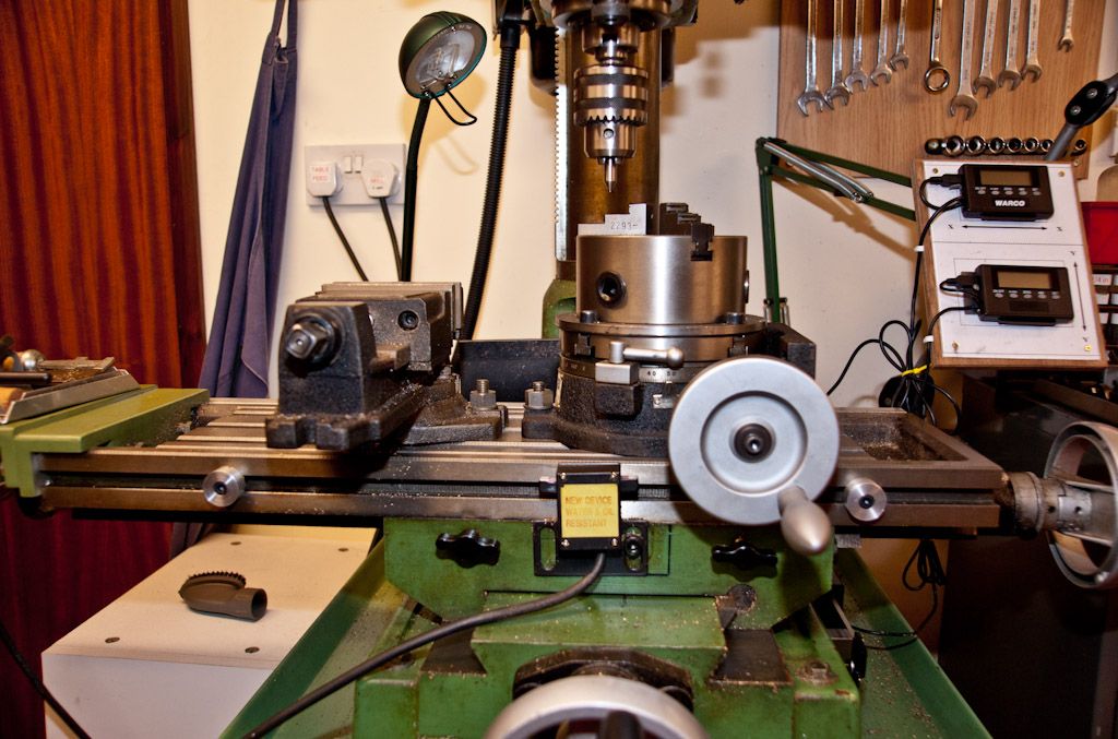
      My solution was simply to position the individual diplays adjacent to the X and Y handwheels. Now when working I can see the job, the digital display and what my hands are doing.

      This set me thinking, a combined, 2 or 3 axis display can only be in one location, setups I have seen tend to have the display above and to the side of the machine. I suppose that someone with good eyesight just gets used to concentrating on the job or the display but only seeing one of the two with their peripheral vision.

      Am I alone in finding the display location critical to easy working.

      Ian P

      Advert
      #15563
      Ian P
      Participant
        @ianp
        #85823
        Jon
        Participant
          @jon

          Well you have to be able to see or its pointless.

          I think your alone to be honest with the hand/eye coordination. Even mounting the readouts where you have, you will still have to take your eye off the job, so no gains in fact worse than all in same area.

          #85826
          Gone Away
          Participant
            @goneaway

            Hi Ian,

            I have my home-built (Schumatech) dro readout mounted on a tilt-swivel monitor mount, generally above and to the side of the machine although I can move it around a bit.

            I can't say I have your problem vis-a-vis wanting to look at the handwheels and the dro at the same time. I never look at the handwheel scales these days. I just look at the dro if I'm machining to a dimension or at the cutter if I'm machining to a visual point. Then again, I've been using this setup for several years and I'm used to it. I think you'll probably settle into a groove once you've used it for a while.

            The few occasions when I want to look at both the dro and the work usually involve drilling or plunging an end-mill to a specific depth, when I want (need) to look at the z-axis display but am mindful of potentially getting a jam-up of swarf at the cutter. Particularly when using the mill/drill in drill-mode. What I actually do is approach closely to the final depth and then back the cutter or drill out and completely clear it and the hole. Then I go back in an concentrate on the dro to the final depth.

            Actually, trying to concentrate on both the readout and the cutter at the same time is a recipe for disaster … or at least you need to pause any feeds while to take a look at the cutter.

            #85858
            Steve Withnell
            Participant
              @stevewithnell34426

              Hi Ian,

              My biggest issue at the minute (actually in winter workshop hibernation at the minute) in mounting the iGaging scales is how to keep the dirt out.

              I'd be interested in your design for this. Actually placing the remote display I'm not seeing any issue at all as it is both small and light.

              One thing I didn't twig until after I bought the igaging scales is that they are 21 bit scales, versus 24 bit of the rest of the chinese scales on the market.

              Steve

              #85861
              Les Jones 1
              Participant
                @lesjones1

                Hi Steve,

                Model engineers digital workshop sell a converter to convert the igaging scale 21 bit output to 2 * 24 bit Chinese scale format.

                http://www.medw.co.uk/wiki/index.php?page=Conversion+Dongles

                Les.

                Edited By Les Jones 1 on 26/02/2012 13:17:15

                #85875
                Ian P
                Participant
                  @ianp
                  Posted by Sid Herbage on 26/02/2012 01:22:57:

                  Hi Ian,

                  I can't say I have your problem vis-a-vis wanting to look at the handwheels and the dro at the same time. I never look at the handwheel scales these days. I just look at the dro if I'm machining to a dimension or at the cutter if I'm machining to a visual point. Then again, I've been using this setup for several years and I'm used to it. I think you'll probably settle into a groove once you've used it for a while.

                  Actually, trying to concentrate on both the readout and the cutter at the same time is a recipe for disaster … or at least you need to pause any feeds while to take a look at the cutter.

                  I think I was too hasty in creating the post originally and did not analyse my problem before putting fingers to keyboard. Actually what I was doing was having to move my head between looking at the table and reading the displays, this is wholly because of eyesight and spectacle limitations. With the displays at table level I can read the displays and still see the job in my peripheral vision.

                  Ian P

                  #85876
                  Ian P
                  Participant
                    @ianp
                    Posted by Steve Withnell on 26/02/2012 13:01:42:

                    Hi Ian,

                    My biggest issue at the minute (actually in winter workshop hibernation at the minute) in mounting the iGaging scales is how to keep the dirt out.

                    I'd be interested in your design for this. Actually placing the remote display I'm not seeing any issue at all as it is both small and light.

                    One thing I didn't twig until after I bought the igaging scales is that they are 21 bit scales, versus 24 bit of the rest of the chinese scales on the market.

                    Steve

                    Since the igaging scales and displays are stand alone, why is the number of bits important?

                    Ian P

                    #85878
                    Les Jones 1
                    Participant
                      @lesjones1

                      Hi Ian,

                      I suspect Steve wants to use the scales with a Shumatech DRO350 or possibly a Yadro DRO. These are both DRO's that you can build yourself.

                      Les.

                      #85879
                      Ian P
                      Participant
                        @ianp

                        Steve

                        The covers I have fitted only give protection from swarf dropping from above, they are just umbrellas really although I would not consider them coolant proof.

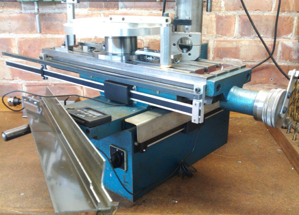
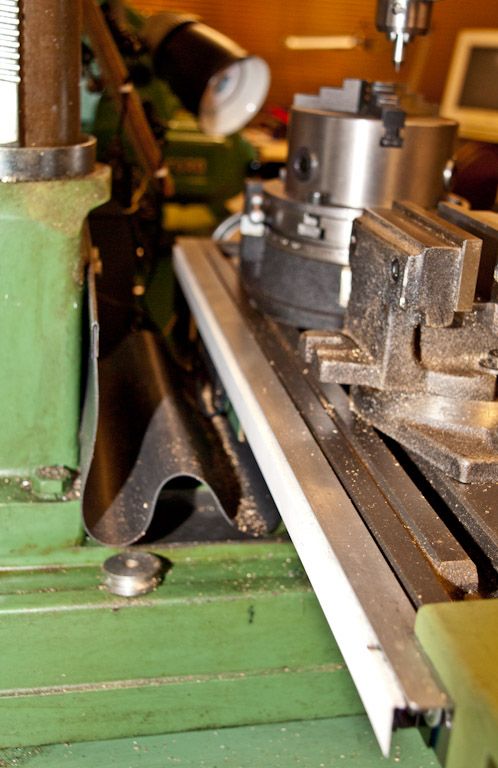
                        Both scales are longer than they need to be but rather than shorten them I fitted (on the X axis) a steel bar above the beam just to give some impact protection.

                        The front of the table has a T slot that carried the travel stops (that I never used) so I used it to mount two aluminium blocks to carry the igaging beam and the 10mm square steel bar (B&Q Plasticene). I had a length of 'F' section aluminium extrusion left over from a polycarbonate roof carport which I modified slightly so that the fins of the 'F' gripped the steel bar. I fixed a steel angle plate at the RH end for the igaging display magnet.

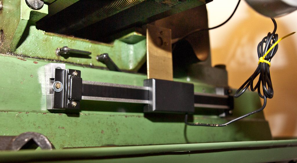
                        The Y axis umbrella is just a length of angle clamped at the back of the machine.

                        The pictures show the scales with and without the covers

                        Ian P

                        X Axis uncoveredX Axis with cover fittedY Axis scale, uncoveredY Axis scale, cover fitted

                        #85883
                        Gone Away
                        Participant
                          @goneaway

                          Interesting arrangement, Ian (and nice pics!). I used the table slot in similar fashion for my (Chinese) scale but was able to attach them directly to the slot (not suspended below them). I made a simlar cover to the one you show on your Y-axis to fit over my X-axis scale and mounted it to the same slot.

                          Like you, it meant dispensing with the travel stops. Then I bought a power feed that had a box containing limit switches to be mounted in that same slot and using the travel stops to operate it. Since the X-axis scale was taking up the room, I'm using the power feed without limit swiches (gulp!).

                          I've recently bought a set of glass scales so I have to go through the mounting exercise again. Perhaps I could use a similar method to yours (and possibly get back the use of the slot for the PF limit switches……although I don't think I have as much height over the base as you do.

                          #85914
                          NJH
                          Participant
                            @njh

                            Hi Guys

                            I decided to mount the "X" axis scale on the back of the table.

                            X Axis on back of table

                            I don't like drilling holes in my machines but in this case it seemed the best option. You will see that I clamped a piece of "L" section Al behind it for protection then was able to squeeze a piece of "L" section plastic to complete some protection on 3 sides


                            The sides of the mill base slope so I made a couple of Al blocks to provide perpendicular mounts and again drilled and tapped the base for these. The "Y" scale is fixed to these by its end caps. I arranged for the moveable sensor to be driven via a (sturdy!) arrangement of levers from the rear of the table – fixed via a bolt where the cross feed screw screening curtain attaches.

                            Y Axis under table


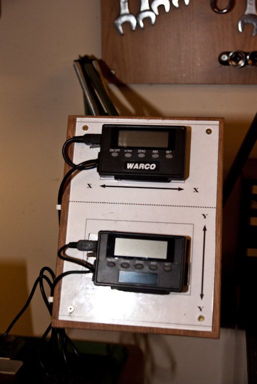
                            The readouts I fixed to a bit of ply covered with paper then with perspex. Two strips of steel were arranged for the magnetic mounts to grab onto. This assembly is mounted on the arm of an old "Anglepoise" lamp so can be moved around to a good position.

                            Mounting for readouts


                            New PF stops


                            This final image gives the "Operators eye" view. Note the new table stops made, mostly, to avoid any disasters with the power feed!

                            I guess it's not as good as glass scales but I find it works pretty well and I'm able to justify the costs ( to myself anyway!)

                            Regards

                            Norman

                            Edited By NJH on 26/02/2012 20:27:40

                            Edited By NJH on 26/02/2012 20:28:51

                            #85939
                            Jon
                            Participant
                              @jon

                              On my small mill like above i mounted the x scale outboard so that the bed stops could be used and still have access to the 'cant live without' bed locks!

                              Personally i would think again before inevitable happens.

                              Fairly sure, its been 12 years, i mounted the Y axis scale along the same lines as NJH above with a cover over similar to Ians. It didnt stop the debris or liquids knackering up the scales, usually got two corrections before they pack up.

                              All three packed up all within a few months. Also had a 3 axis readout from Warco still got mounted in the usual place.

                            Viewing 13 posts - 1 through 13 (of 13 total)
                            • Please log in to reply to this topic. Registering is free and easy using the links on the menu at the top of this page.

                            Advert

                            Latest Replies

                            Home Forums Workshop Techniques Topics

                            Viewing 25 topics - 1 through 25 (of 25 total)
                            Viewing 25 topics - 1 through 25 (of 25 total)

                            View full reply list.

                            Advert

                            Newsletter Sign-up