Murray’s Hypocycloidal Engine – Antony Mount

Advert

Murray’s Hypocycloidal Engine – Antony Mount

Home Forums Stationary engines Murray’s Hypocycloidal Engine – Antony Mount

Viewing 23 posts - 26 through 48 (of 48 total)
  • Author
    Posts
  • #354698
    Neil Wyatt
    Moderator
      @neilwyatt
      Posted by Mick B1 on 18/05/2018 20:23:06:

      Lotsa work to make 1/4 teaspoon of swarf… laugh

      NIce one

      Advert
      #354705
      Mick B1
      Participant
        @mickb1

        Ah, thanks, and I meant to ask about gaskets.

        My previous engines from Stuart's and PM Research had gaskets in the kits.

        I used to make gaskets for my old Beeza A10 (back when the world was young and men were strong) from cornflakes packets (and red Hermetite where the faces had been bruised and butchered, mostly but not invariably by previous owners…).

        But they're way too thick for model engines. I bought some 10 thou gasket paper but found it dead fiddly.

        I was wondering whether the use of plastic gasket from a tube is regarded as excommunicable heresy, or whether the stuff is actually more trouble than it's worth from the future maintenance viewpoint? indecision

        Edited By Mick B1 on 19/05/2018 19:32:05

        #354708
        JasonB
        Moderator
          @jasonb

          I use the liquid gasket on all my engines

          #354709
          Mick B1
          Participant
            @mickb1
            Posted by JasonB on 19/05/2018 19:54:38:

            I use the liquid gasket on all my engines

            OK, thanks – I'll suck it an' see.

            #354736
            geoff walker 1
            Participant
              @geoffwalker1

              Mick,

              This stuff is great for gaskets, ebay item number 173028673495.

              0.1mm PTFE sheet, high temperature resistant, 300 x 1000 mm.

              Very easy to cut and shape with a small sharp craft knife and "cheap as chips" to buy

              I used it for gaskets on my small jepson engine, gave perfect seals all round.

              Comes from China but worth the wait.

              Geoff

              #354752
              Ian S C
              Participant
                @iansc

                I use liquid gasket, I used to use oiled brown paper from paper bags, looks like the paper bags are going to make a come back.

                Ian S C

                #354803
                Neil Wyatt
                Moderator
                  @neilwyatt
                  Posted by Ian S C on 20/05/2018 12:35:00:

                  oiled brown paper from paper bags

                  Beat me to it

                  #357995
                  Mick B1
                  Participant
                    @mickb1

                    Right. Still haven't got to gasket-making stage yet.

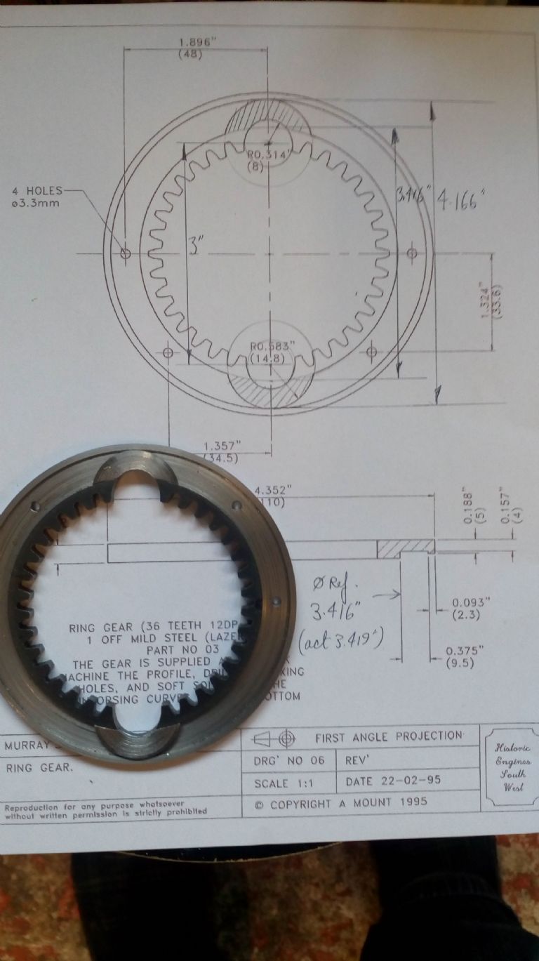
                    Yesterday I was making the reinforce arcs for the laser-cut ring gear supplied wi' kit. I've drawn in the arc where they meet the inner toothed ring when machined to the drawing, and shaded in the bits I gotta make. reinforces in loose.jpg

                    Oh, momma, I really hadda do some baad things here…laugh

                    In order to get the arc radius right(-ish) at the base of the reinforce, the only easy way I could see to do it was to use a long 3/16" toolbit in my boring bar/flycutter, set out to the 1.708" radius of arc, then set a turned blank in the vice 1.5" above centre height – pretty close to the top of my vertical slide travel.

                    Shape of the toolbit reflected my earlier punt at doing a sort of interrupted trepanning cut through the face to save chopping away all the metal on the underside. I didn't think I'd get away with that, and when it became clear I wasn't going to I abandoned it before I broke the tool or wrecked the blank.

                    So then I let down the slide 20 thou at a time and bored out the arc on the slowest feed longitudinally. Took Gawd knows how many cuts.

                    boring reinforce.jpg

                    But eventually it worked, as you can see in the first pic. I was offering up the turned ring gear to see if the workpiece would fit between the inner and outer diameters over the last 10 thou or so, and it came right within about 2 thou of the expected vertical slide setting.

                    Then I could carefully part off the 2 reinforces on a slow-speed interrupted cut.

                    Now I gotta soft-solder the things in place prior to a final face skim to clean up.

                    'Spect that might be another story… frown

                    Edited By Mick B1 on 16/06/2018 10:32:09

                    Edited By Mick B1 on 16/06/2018 10:32:55

                    #358079
                    Mick B1
                    Participant
                      @mickb1

                      I couldn't get the flux-cored soft solder I use on electrics to take properly, so I tried silver solder.

                      That worked, but I've got a couple of stray blobs oozed out. They won't (AFAIK) interfere with owt, but they look untidy. blush

                      Think I'm gonna hafta Dremel out as much as I can with those little rotary diamond file affairs, then finish off with the point of a Swiss file ground like a watchmaker's turning tool.

                      Unless anybody would please tell me a better way? angel

                      #358429
                      Mick B1
                      Participant
                        @mickb1

                        Well, the Dremel (actually Rotacraft) didn't really work – there was too much risk of carving into the steel underneath the silver solder – but I found a titchy little parting tool I'd ground for titanium earings I was turning on the little Sieg C0.

                        So I mounted that in the Warco pointing at the chuck, gripped the inner gear ring on the outside jaws, set the tool to kiss the recessed face and rotated the chuck by hand until the reinforce hit the tool. It peeled off a strip of silver solder. I had to back off a bit on the thickest bit of the blob and do it a few thou at a time, and of course it left a tiny triangle untouched where the flat-faced tool couldn't reach, but maybe 20 minutes' work cleaned off almost all the blobs. Then I blacked the part with gun-blue creme, washed it and emeried the o/d and front face.

                        ring gear.jpg

                        Maybe my standards are low, but I think that's now OK. I wish I could get rid of the joint line on the lower reinforce, but I'm not yet sure I care enough to take the trouble – I thought about filling it with soft solder but there's probably some solder-hostile crud in there by now so I don't know how easy – or risk-prone – that might be.

                        Maybe I'm making a meal of stuff some of you probably think is nursery-slope work… laugh

                        #358440
                        JasonB
                        Moderator
                          @jasonb

                          Looks good to me, you can always leave the crank arm over that joint when the engine is on displaywink 2. Even if it had soldered up a bit tighter the silver solder can tarnish over time and leave a black tell tale.

                          #358548
                          Mick B1
                          Participant
                            @mickb1
                            Posted by JasonB on 19/06/2018 13:25:17:

                            Looks good to me, you can always leave the crank arm over that joint when the engine is on displaywink 2. Even if it had soldered up a bit tighter the silver solder can tarnish over time and leave a black tell tale.

                            Thanks, but sadly I can't – the crank arm's behind the hypocycloidal gear set, and the piston rod bigend only goes straight up and down between the inner radii of the reinforces. Anything I did to widen it would probably just look as if it was there to hide summat… blush

                            #358554
                            JasonB
                            Moderator
                              @jasonb

                              Just had another look at Anthony's design and yes it can't be hidden. Short of cutting your own from a slice of CI bar there is not that much that can be done, the internal gears are not that hard to cut.

                              #360593
                              Mick B1
                              Participant
                                @mickb1

                                Think I'm just about finished for piece parts now, except for the soddin' frame feet, which I think I'm going to bolt on rather than silver solder, after the last nail-biting experience.

                                I simplified the main bearing housing to a square u-shape and again bolted that on, there being no discernable reason not to.

                                I saved myself a 48 mile roundtrip or two-day delivery wait by drilling the tapping holes for the 8BA main bearing retainer bolts 1/16" instead of the proper 1,8mm, and it's cost me not 1, but 2 broken taps. Stupid of me to try it, really – I get away with it once, and then think it's an acceptable technique. Blind holes – not a hope in Hades of gettin' 'em out. And I couldn't be ar$ed to remake the bearing housing – not at this stage – but I did find I could resharpen what was left of the broken plug tap. And if I drilled 5/64" or 2,00mm for tapping, the thread cut much easier and was still strong enough (which I hadn't at first expected).

                                So one of the bearing retainer bolts is in a bit of a 'not to drawing' position. Whether or not I ever fix it probably depends on how persistently it embarrasses me to see it later… blush

                                #361618
                                Mick B1
                                Participant
                                  @mickb1

                                  I've done the feet, bolted them to the A-frames and to the baseplate, also done a casual assembly with 4 of the longitudinal tiebars.

                                  MurrayAssy2.jpg

                                  MurrayAssy1.jpg

                                  There's 2 thou clearance between the crankshaft diameter and the holes in the bearings, which are 4 inches apart, and it just slipped through and turned freely, just like that.

                                  Now, it's true that the Polly Models kit has some of the fastener holes and the bearing box cutout already in place, but there are still a lot more than enough places you can introduce variations to build up some problematic cumulative errors.

                                  So, at the moment that's looking good. Still plenty of opportunities to screw up yet, though… embarrassed

                                  #364997
                                  Mick B1
                                  Participant
                                    @mickb1

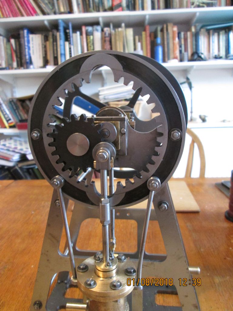
                                    Right. 'Tis done – more or less. I might make oil cups for the main bearings and eccentric strap, and I'll probably paint the frame, cylinder and the flywheel except its rim, but it runs from a big bicycle pump – though my 12V tyre inflator doesn't seem to shift enough air. Unsurprising as the cylinder swept volume's much bigger than my Sturat Beam, which it can just operate.

                                    2018-08-01 12.39.57.jpg

                                    Took me several tries to get it running.

                                    First I tried a Nylon 66 piston ring. Maybe that would've worked if I'd worked up a mirror-smooth bore, but as it was I couldn't get an air seal without a tight frictiony fit. So I took some cotton kitchen string and smeared it with LM3, and that finally gave a smooth-fitting seal.

                                    There was a few thou shimmy on the eccentric because I'd started it from a bit of CI that was pretty much exact length, and that was just fouling the protruding tip of one of the bearing support bolts once per rev, till I found a way to chop the tip off without dismantling the whole thing.

                                    The Loctite 271'd interference fit of the mainshaft to the crank throw wasn't up to the torque, and shifted – so I drilled 3/32 through both and pinned it with silver steel. Meant I had to fiddle the valve chest cover with its 11 x 8BA studs and nut off and on again so as to reset the lost valve timing. Growled away half a morning on that.

                                    But the stupidest issue was my inlet assembly. I had a hollow hex tube feeding the valve chest, and a plain inlet pipe screwed in at a right angle to that. Screwed it in so far that it completely occluded the 'ole into the hex tube, didn't I? So the compressed air wasn't even reaching the valve, never mind the cylinder. I really don't wanna say how long it took me to find that. Duh.

                                    There are two weird-shaped tie-rods from cylinder to stator ring. Only the Michigan original has these, and I can't really see the point of them in the model as the four 5BA bolts holding cylinder to frame should easily be adquate. The drawing's not completely dimensioned and there's no obvious easy way to calculate the compound angle, so I fabricated them from steel components screwed together, which took quite a while as suck-it-and-see seemed the only method.

                                    So. I've got a nice new model now.

                                    Is it because of the laser pre-cut frames and gears that I now feel a bit of a cheat? I strongly doubt that I'd ever've worked up the commitment to build such a thing without – dunno how I'd've done the gears at all with the kit I have.

                                    Thanks to all who've answered questions and provided advice, even if I haven't always followed it. smiley

                                    #365501
                                    Mick B1
                                    Participant
                                      @mickb1

                                      Whoopee doo!

                                      It wasn't that the little inflator didn't have the puff!

                                      It was that I should've retarded the timing by about 10 degrees instead of cracking the inlet ports at the deadcentres. Thunk that thought drifting off to sleep last night after another pointless, meandering episode of Dicte on the telly.

                                      Carol's delighted that I don't now have to buy an expensive compressor… angel (we'll see later)

                                      Anyway, here's a video of it running:-


                                      Still haven't made my mind up whether to paint it – quite fancy leaving it bare metal or maybe laquered – any opinions or recommendations?


                                      Edited By Mick B1 on 04/08/2018 12:19:34

                                      Edited By JasonB on 04/08/2018 13:03:28

                                      #365505
                                      JasonB
                                      Moderator
                                        @jasonb

                                        That runs nice and slowly, smooth as well even with what is quite a small flywheel.

                                        You have done a neat job with the metalwork so leaving bare would certainly be an option, If you decide to paint than I think these early engines look good in a satin black which is not unlike the finish already on the flywheel, gears and base plate.

                                        #365654
                                        Mick B1
                                        Participant
                                          @mickb1

                                          Thank you for that. I think I got a bit lucky – there's still a minor tight spot at about 5 o'clock that I think can *just* be noticed in the video, once you know it's there. I'm reluctant to try to fix it in case of creating other issues.

                                          When I get to it, I think I might get smoother running from my other engines if I re-examine the timing to see if it's too close to the deadcentres.

                                          #365686
                                          geoff walker 1
                                          Participant
                                            @geoffwalker1

                                            Nice work Mick, been a good thread this some interesting input

                                            Geoff

                                            #365704
                                            Neil Wyatt
                                            Moderator
                                              @neilwyatt

                                              Nice work indeed.

                                              Neil

                                              #365746
                                              Mick B1
                                              Participant
                                                @mickb1

                                                Thanks for the kind words.

                                                #365763
                                                Jon Lawes
                                                Participant
                                                  @jonlawes51698

                                                  What a lovely piece of work, well done.

                                                Viewing 23 posts - 26 through 48 (of 48 total)
                                                • Please log in to reply to this topic. Registering is free and easy using the links on the menu at the top of this page.

                                                Advert

                                                Latest Replies

                                                Home Forums Stationary engines Topics

                                                Viewing 25 topics - 1 through 25 (of 25 total)
                                                Viewing 25 topics - 1 through 25 (of 25 total)

                                                View full reply list.

                                                Advert

                                                Newsletter Sign-up