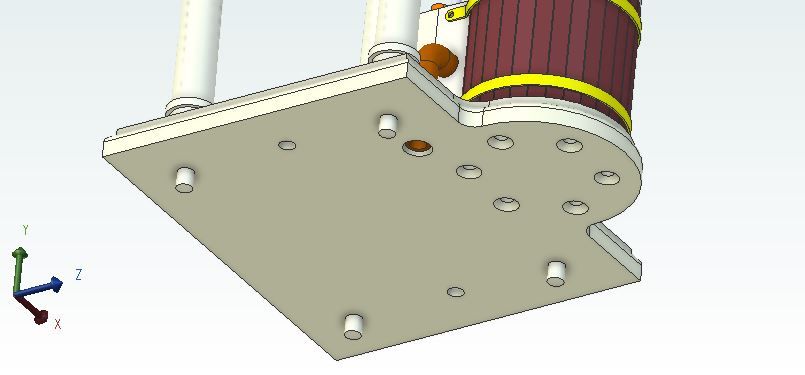
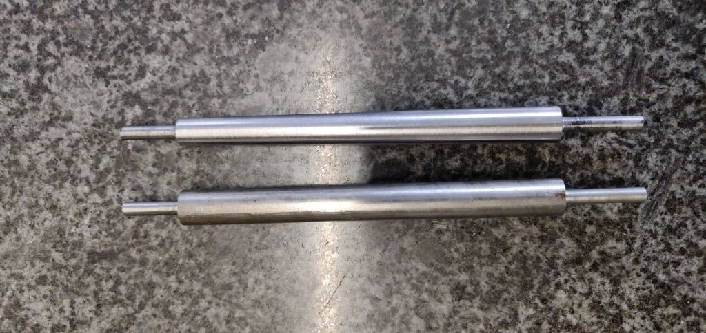
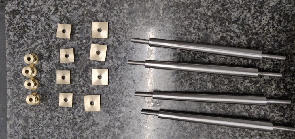
I have just started the base today. Are the columns fixed to the base with nuts under the base? I can see that the holes for fixing the cylinder to the base are countersunk but the holes for the columns aren't.
Sorry Ian, just the six photos and text in the article which I thought showed each stage fairly well, if you have a specific part of the machining you are unclear about then let me know and I'll see if I can add a bit more.
I have just started the base yesterday. Are the columns fixed to the base with nuts under the base? I can see that the holes for fixing the cylinder to the base are countersunk but the holes for the columns aren't.
Yes I just used nuts for them, you could leave out the CSK to the cylinder holes and just use some cap head screws for the cylinder but will have to cut some clearance holes in whatever wooden base you choose.
I suppose the spigots on the columns could be made a little shorter and the holes counterbored for a nut and clearance for a socket if you want a completely flush bottom.
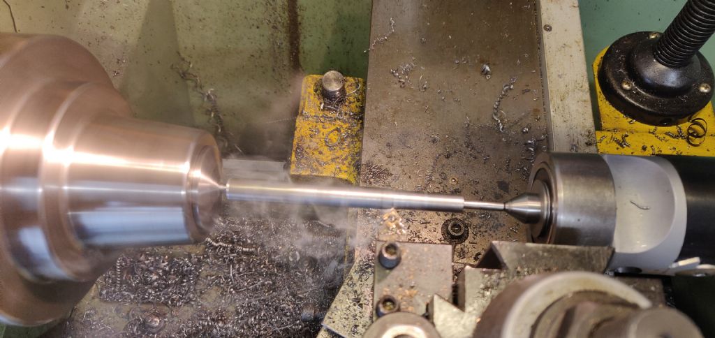
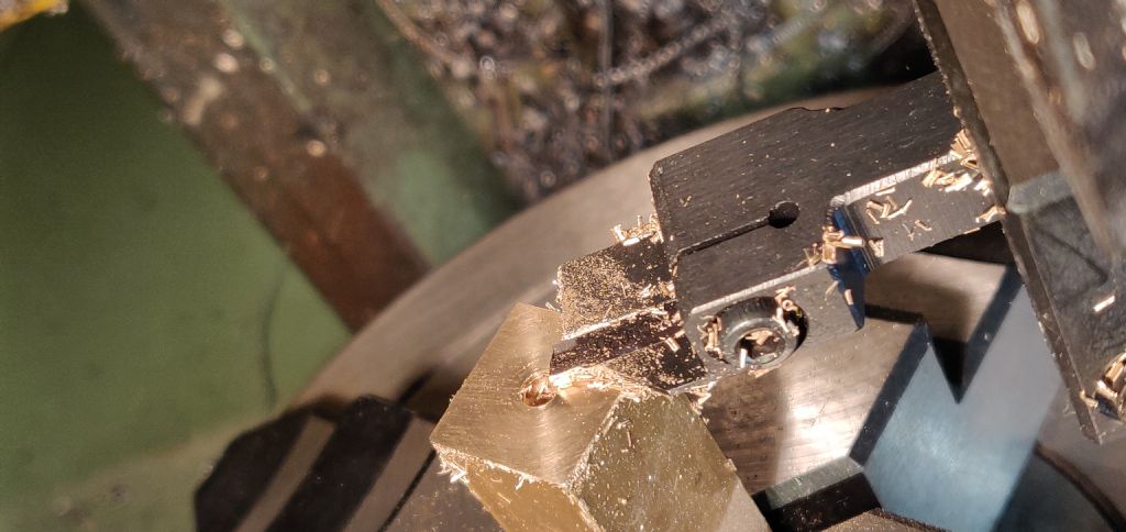
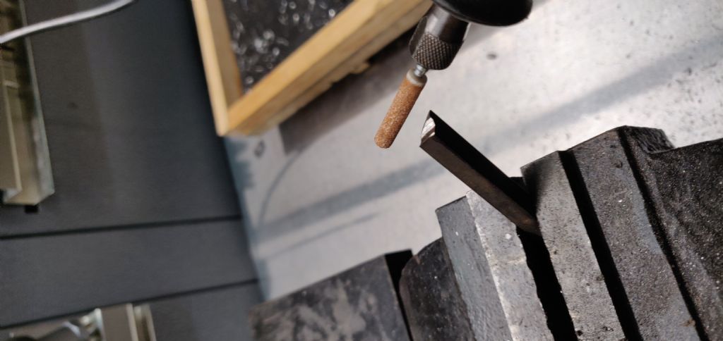
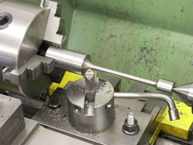
Jason I am trying to find the easiest/best way to make them. I have tried a couple of different ways on the lathe and made a holder for the chuck which will take flat bar. Also tried from round bar which gave better results and was easier to turn. Finished off the round ends on the mill and rotary table.
Yes ive got a four jaw. Tried this as well for flat bar and still didn't turn out great. Do you normally make them from flat bar or round stock or does it just depend on whats to hand?
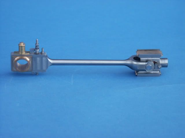
I've done most from rectangular section either flat bar of sized from a larger block. I think it is the easier way for someone with limited equipment as you don't need a way to index the round stock as rotate it to put in the reamed holes, cut the slot and then mill the faces down.
I have dome larger ones by starting with round stock which is handy when you have large curving transitions which can be done with a ball turner.
Thanks Jason. You produce some very fine work and its great to have you help us out and share some knowledge. A ball turner has been on my list of things to make but now that I see what your doing with it Ill have to bump it up the list a bit. Maybe just after the belt sander project that's just about to start. Whats the one in the picture for?
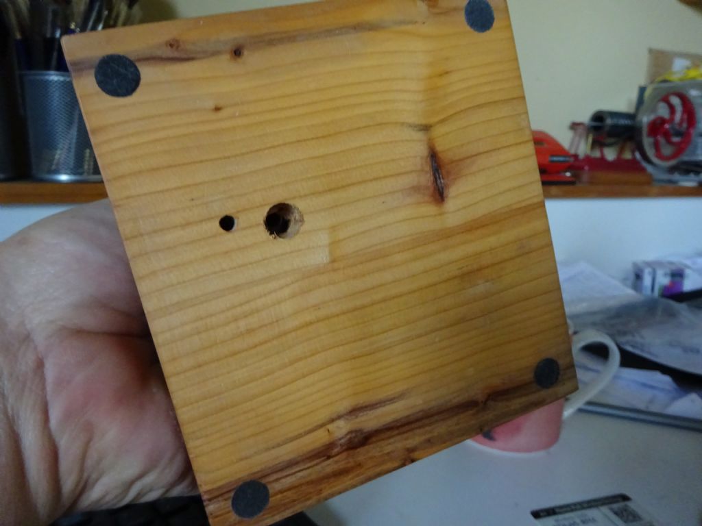
The photos and drawings show a pipe connected from the valve chest to a hole in the base plate which is bolted to a wooden base. Where does the steam/air exhaust to ? Is this pipe not used when running ?
Hole in the base is larger than the pipe and as can be seen from teh image of the underside that I posted above the pipe does not go to the bottom of the hole. This will allow exhaust air to freely escape, If running on steam then I would suggest plumbing into the boilers blast pipe via an oil seperator.
I also put small baize "feet" on the corners of my wooden bases which offers a second route for the exhaust air to escape.
I have a problem. I want to but 2 Muncaster flywheels from lee but he doesn't post to Australia.
Could I ask if a fellow ME in England buy 2 for me and post to me here in Australia ? I would of course send over the money. It would be easier if the person has a Pay Pal account. They could find out from the local Royal mail PO how much it would cost for postage and add on some more for their troubles.
John Chappell,
30 Lamerough Pde,
Caloundra QLD 4551 ( Sunshine Coast 100 Kms north of Brisbane )
I rather like the look of the naked engine, the cladding looks good for sure but I think naked especially if the cylinder was brass would also be very nice.
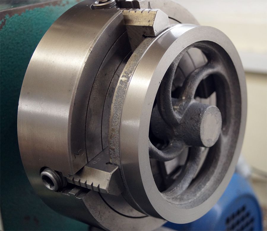
Well surely thats a sign of a quality casting, just started on the flywheel (waiting for a new compressor for the Jowitt).
I clocked up the inside of the rim or as near as for an unmachined casting and it took just 1.0 mm removed to clean and true the rim outer face and only 0.8mm to clean the rim side, I doubt it gets much better than that.
Morning Jason, would appreciate your thoughts on increasing the crankshaft from 8 to 10mm its just convenience really. I have 10mm ground bar and my smallest boring bar will go down to 10mm. It would mean the bearings growing by 2mm but it looks as if the pedestals have enough meat. I would rather bore for the crank than ream, it would just look a tad heavier in the crank area but I don't think too much. What do you think..?
You will only get 2mm wall thickness to the eccentric's boss for the grubscrew to hold into so may want to up the boss dia to 16mm which will mean it's not a full circle but should not matter.
Bearing pedestals will take the bigger bearing or you could make all the widths 2mm wider which would allow for a 10mm radius at the top and therefore keep the same thickness material.
Jason, would silver steel be ok for the crosshead guides or is it the wrong material, its the nearest size I have on the shelf. I have some 100 x 40 x 8mm pieces which I thought I could get down to size and most of the shape with the 25mm end mill, if its not suitable I will get some bright steel in.