Muncaster’s Simple Entablature Engine

Advert

Muncaster’s Simple Entablature Engine

Home Forums Stationary engines Muncaster’s Simple Entablature Engine

Viewing 25 posts - 76 through 100 (of 156 total)
  • Author
    Posts
  • #434409
    geoff walker 1
    Participant
      @geoffwalker1

      Oh dear, broken tap Paul.

      Sorry have to agree with Jason, you're fault.

      I'm making this engine and I also made the bearing housings from steel, I largely avoid aluminium, much prefer working with steel, just a personal choice.

      What I would say is that I drilled the tapping hole right through the housing, so no possibility of the tap bottoming in the blind hole and just the taper tap will give you enough threads for the cap screw or stud.

      Also with small taps don't hold the work in a vice, hold the work in one hand and the tap and holder in the other. This will give you much more feel, you can sense more easily when the tap is tightening up so you can relieve the cut. Use a small amount of cutting paste, trefolex or similar. Also agree with Jason a slghtly bigger tapping hole helps

      I started home machining / model engineering 10 years ago this month when I bought the Myford. I had no previous experience and during that time I have made lots of tools accessories, models etc, threaded countless holes and I have not broken a tap yet. I do take great care, most of my taps belonged to my dad who was an engineer. When I'm done with them I'll pass them on to my lad, also an engineer. He can break as many as he likes, I won't be around to see it!!

      Geoff

      Advert
      #434456
      paul rayner
      Participant
        @paulrayner36054

        I will take it on board to go up 0.1 next time.

        I called at the local suppliers on my travels today and picked up an Osbourn 1st tap and did the rest of the holes a treet.

        Geoff. it was a blind hole but, I like you on small stuff hold it in my hand, but this is, to be honest, is where I think I went wrong, I used a small tap wrench instead of one of those pin chuck types.

        lesson learned

        regards

        Paul

        #434458
        JasonB
        Moderator
          @jasonb

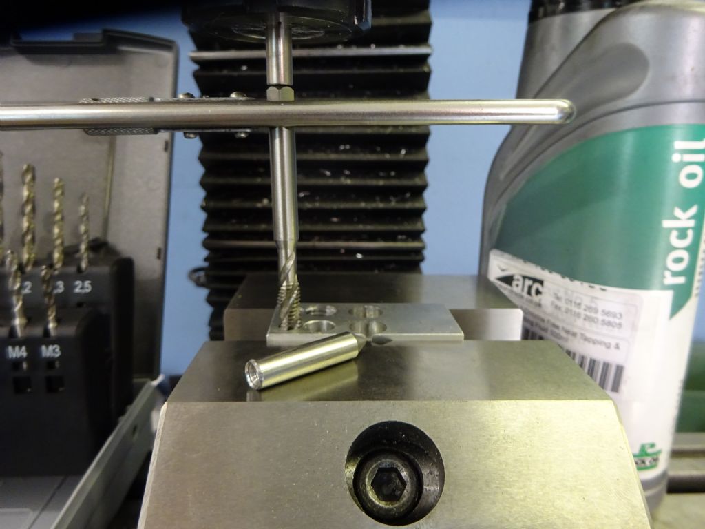
          My preferred method is to tap the part while it is still in the machine from maving been drilled. The spindle is directly above the hole so a simple guide can be held in a chuck or collet and used to guide the tap thus keeping it perfectly vertical. I tend to use a small 4" long tap wrench on the round shank of the tap which will slip if you push things too hard.

          The guide can simply be a piece of 1/4" or 6mm steel with a 60deg point turned on one end and ctr drilled at the other so you can use it with taps that have a ctr hole or male end, apply light quill pressure as you rotate it with the other hand.

          photo 176.jpg

          I have said before that I generally specify a deep hole where the material allows so there is no problem with swarf or need to go through three types of tap though a spiral flute also does away with that need. You do not gain much more holding capacity once you get to 1.5 times the thread diameter in depth. So 5mm of actual thread on an M3 hole will be more than enough.

          #434592
          paul rayner
          Participant
            @paulrayner36054

            Jason I'm not brave enough to do it that way on the mill with such small taps. I do however with bigger ones M6 +

            as a matter of interest I thought I would "have a go" at removing that broken tap. I drilled through from the other side and to my surprise when the drill met the tap I measured it and the tap was only 3.5mm in the work. I then got a small punch? drift? one of them round bar things with a flat end on lightly tapped a few times each side and bugger me it came out! So I need not have made another bearing blockfrown

            ah well it's all fun eh

            regards

            Paul

            #434768
            paul rayner
            Participant
              @paulrayner36054

              Jason

              I'm waiting of some reamers etc to progress, so I thought I would make a start on some studding for the main bearings.

              A couple of stupid questions if I may

              1) did you use washers? as it looks as though you have when you expand the picture but they look painted or is it just a shadow from the camera light

              2) How did you tighten the nuts up without chewing up the paint????

              3) did you locktite the studs in to a set depth

              regards

              Paul

              #434778
              JasonB
              Moderator
                @jasonb

                1. No Washers

                2. Very slight chamfer on the underside of the nut and no overdone with the paint thickness.

                3. The trick is to use a thread lock to fix the nut onto the stud and once set put them in like bolts, that way you set the exposed length of stud when it is easy to do it.

                #434783
                paul rayner
                Participant
                  @paulrayner36054

                  cheers Jason yes You learn sumat new every day eh!

                  regards

                  Paul

                  #435107
                  john Chappell 1
                  Participant
                    @johnchappell1

                    Hi Jason,

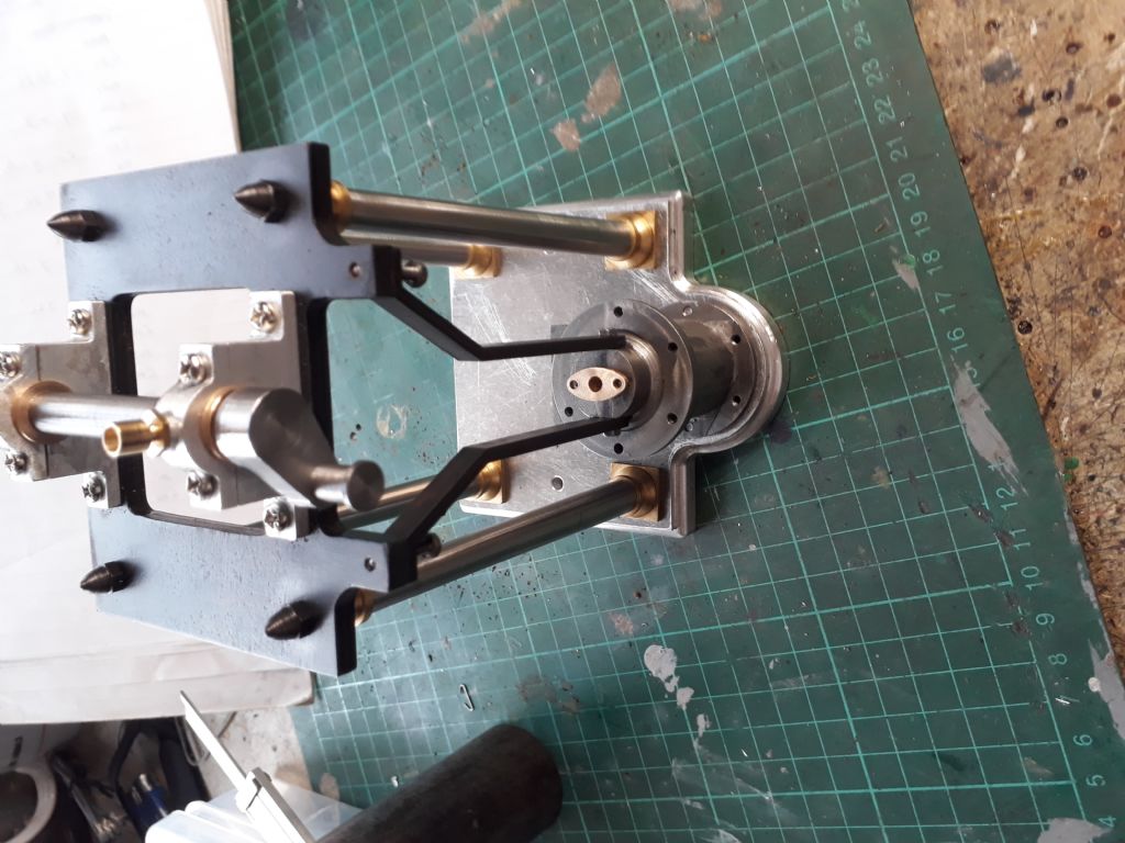
                    Attached photos of my build so far. By the way I used your method to make the cross head guides, Thanks.

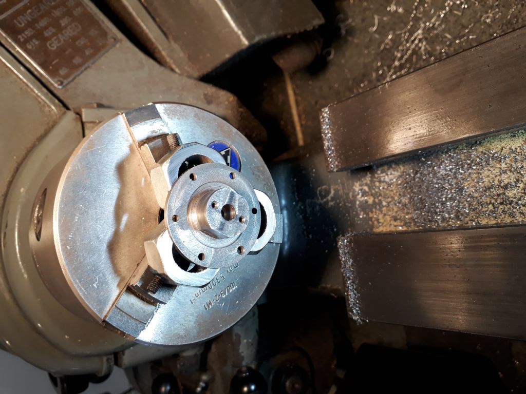
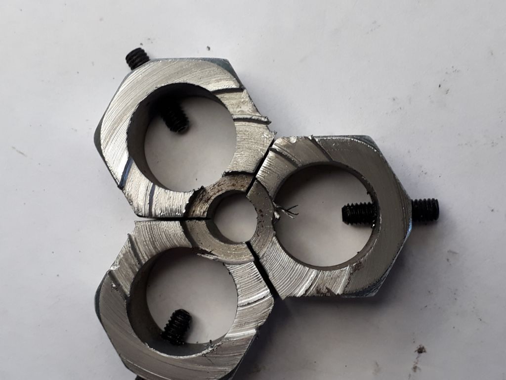
                    It may be of interest to others how I made a poor mans "soft jaws." for machining the cylinder cover. I bored out 3 large nuts to fit over the chuck jaws and added grub screws to hold them on the jaws. In this case I tightened up jaws on the nuts and then bored out a recess slightly smaller than the OD of the cover.

                    Regards,

                    John

                    ps sorry I could not work out how to insert photos

                    #435123
                    JasonB
                    Moderator
                      @jasonb

                      John, this should explain about adding photos

                      #435461
                      john Chappell 1
                      Participant
                        @johnchappell1

                        Here are the photos!

                        20191024_131539.jpg20191024_132114.jpg20191029_073305.jpg

                        Edited By JasonB on 01/11/2019 06:55:32

                        #435494
                        Mick B1
                        Participant
                          @mickb1
                          Posted by john Chappell 1 on 28/10/2019 22:03:40:

                          It may be of interest to others how I made a poor mans "soft jaws." for machining the cylinder cover. I bored out 3 large nuts to fit over the chuck jaws and added grub screws to hold them on the jaws. In this case I tightened up jaws on the nuts and then bored out a recess slightly smaller than the OD of the cover.

                          Regards,

                          John

                          That's neat – even though I've got soft jaws I sometimes come across diameters I want to hold that don't fit my existing machining, and I know I'm unlikely to come across a similar diameter requirement anytime soon, and don't want to machine away what I've already got. This provides a workable solution for the 'one time' oddball job. Thanks.

                          Edited By Mick B1 on 01/11/2019 10:55:31

                          #436770
                          JasonB
                          Moderator
                            @jasonb

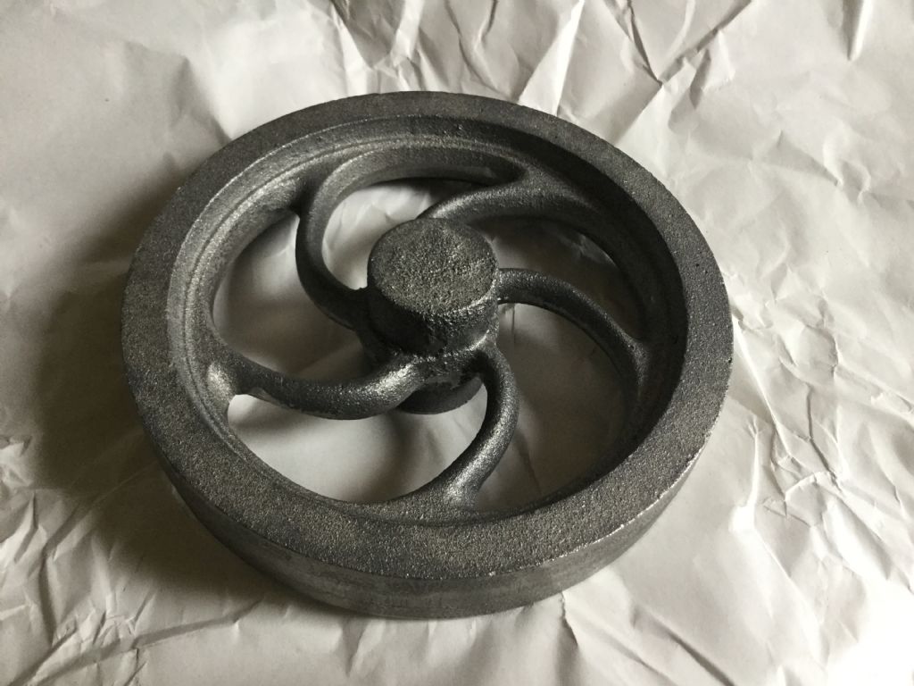
                            Don't all rush but Lee has the Muncaster flywheel castings back in stock here get them while there hot!

                            Edited By JasonB on 10/11/2019 20:25:58

                            #436773
                            john Chappell 1
                            Participant
                              @johnchappell1

                              Thanks Jason. Very good news… but he doesn't post to Australia! so how is one to buy? I wanted to buy 2 or more if others in Australia would like them

                              Regards,

                              John

                              #437083
                              Stuart Smith 5
                              Participant
                                @stuartsmith5

                                I ordered a flywheel casting from Lee on eBay on Sunday and it arrived today. Looks good. Flywheel

                                #437825
                                Philip Borland
                                Participant
                                  @philipborland84291

                                  Is there a material list anywhere, or do I need to work through all the components to work out what is needed ?

                                  I plan to start this and don't want to have to keep making trips to the metal monger.

                                  #437828
                                  JasonB
                                  Moderator
                                    @jasonb

                                    Good to hear another one is going to be built, give me a couple of hours and I'll post a list.

                                    #437847
                                    JasonB
                                    Moderator
                                      @jasonb

                                      I think I have said before that I am not a fan of lists of materials as I feel sitting down and going through the drawings is a good way to get to know the parts and think about how you will machine them with what tools are available. However I can see the appeal to those who don't have much material in stock and want to get all that is required in one go to keep postage costs to a minimum.

                                      I have done a bill of materials in both Word and PDF format that can be downloaded. The sizes given are the minimum that the part will come out of, the individual builder will need to make allowances for Cutting, parting sawing and how much they need to hold the part. I have also indicated where it will be easier to buy small amounts of imperial stock as not all ME suppliers keep metric sizes and there is little point in buying 3m lengths when you may only need 10mm.

                                      Any Queries please ask.

                                      #437883
                                      Philip Borland
                                      Participant
                                        @philipborland84291

                                        Excellent – Thanks Jason

                                        #437887
                                        john Chappell 1
                                        Participant
                                          @johnchappell1

                                          Regarding bending exhaust pipe.

                                          I selected a piece of pipe longer than needed, crimped one end and then filled the pipe with solder.I then bent the pipe with my home made pipe bender, threaded one end ( reversing the die to finish up close to the bend ), cut off to length, deburr and finally heat up and pour out the solder.

                                          Worked well for me!

                                          #438113
                                          Philip Borland
                                          Participant
                                            @philipborland84291

                                            I found these on a US site

                                            **LINK**

                                            Anyone else want one ? I have a friend coming over second week of December and I could slip a few in his luggage

                                            #438494
                                            Philip Borland
                                            Participant
                                              @philipborland84291

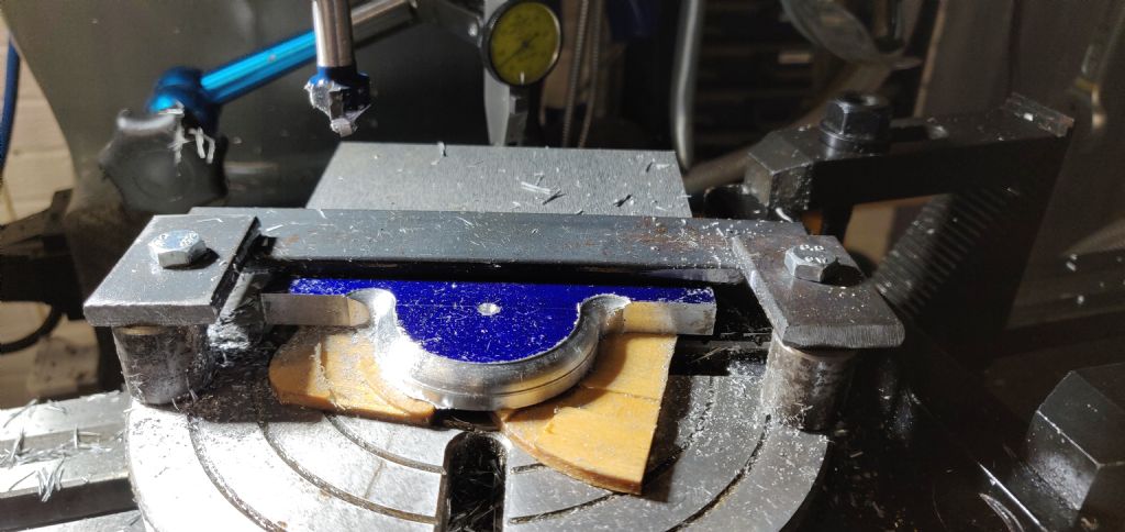
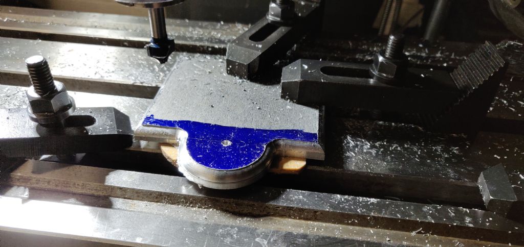
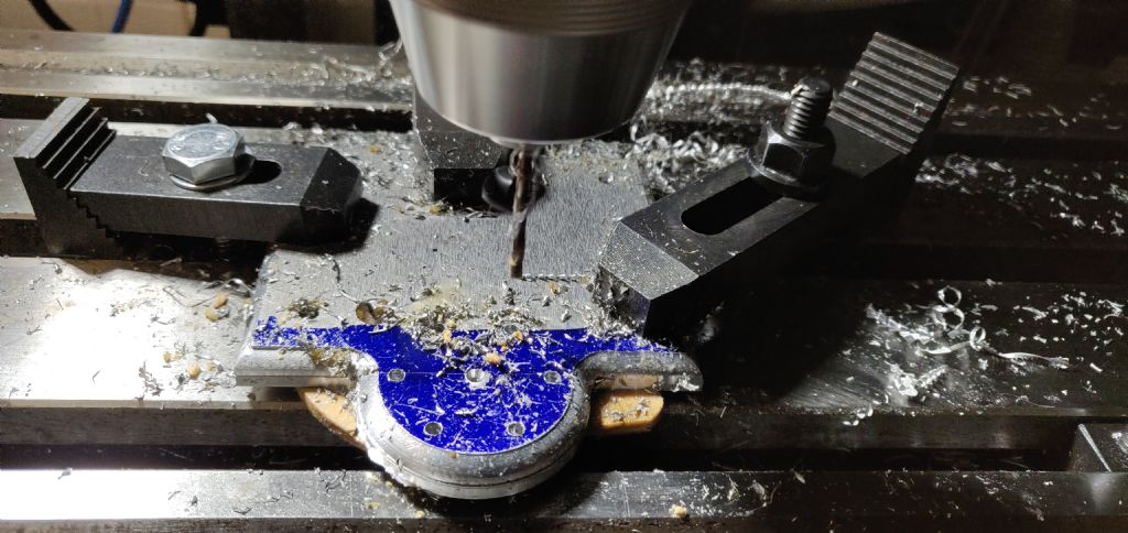
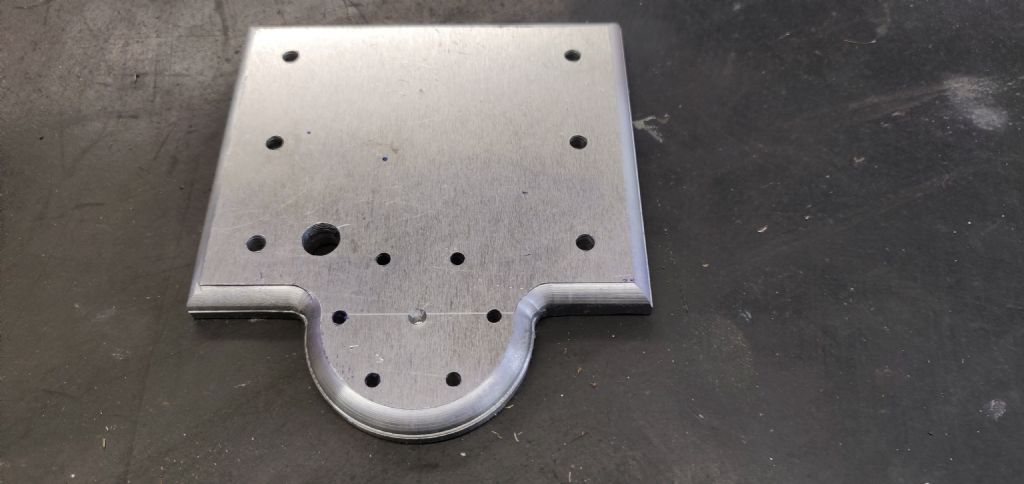
                                              Thought I'd share my build.

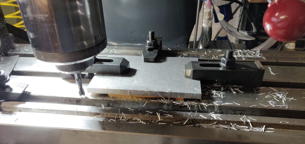
                                              Squaring the stock

                                              img_20191122_134103.jpg

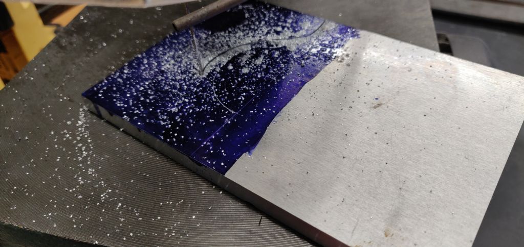
                                              Cutting out the excess using a scroll saw – saw this on clickspring (youtube) and it works really well.

                                              img_20191122_135808.jpg

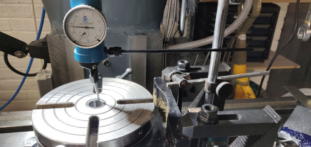
                                              Centering the rotary table with my new toy -works great

                                              img_20191122_143917.jpg

                                              Struggled with clamping this on my small roatary table. I used a woodworking router bit for the roundover and it worked well

                                              img_20191122_182401.jpg

                                              Working my way round the edges

                                              img_20191122_191039.jpg

                                              PCD was easy with the DRO

                                              img_20191123_134843.jpg

                                              Looks good!

                                              img_20191123_135415.jpg

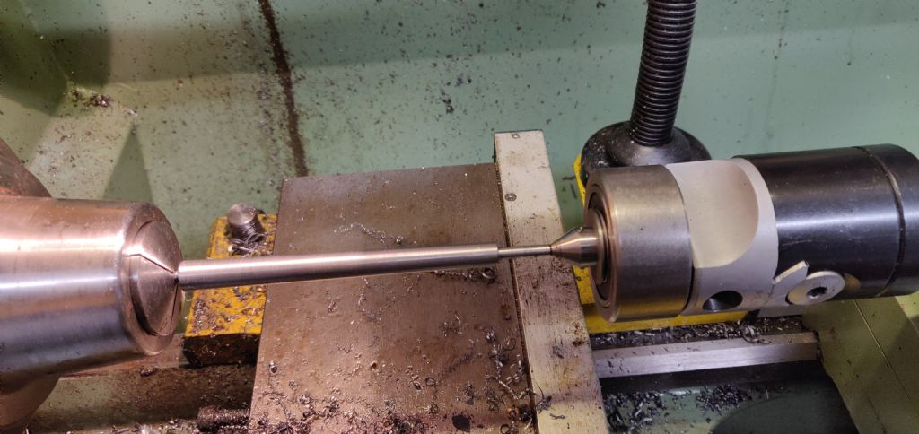
                                              I built a live centre for my boring head. 2 quid bearing from ebay, then made an insert to hold the centres from my tailstock live centre. Used a dti to give me 1mm of offset at the tail end.

                                              img_20191123_190635.jpg

                                              #438495
                                              Paul Lousick
                                              Participant
                                                @paullousick59116

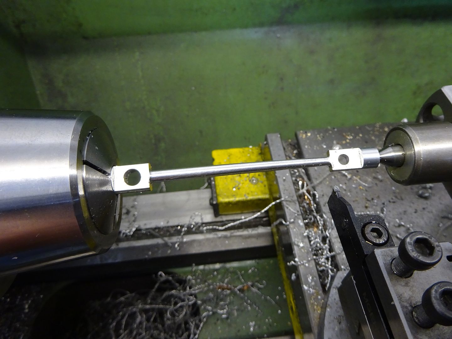
                                                The bottom photo shows the job supported at the tailstock by your live centre (I assume in the offset position) but the headstock end in a collet instead of a centre. Did the work piece just flex as it was rotated ?

                                                Paul.

                                                #438496
                                                Philip Borland
                                                Participant
                                                  @philipborland84291

                                                  Paul,

                                                  yes just flexed – as per the advice in the magazine articles.

                                                  Phil

                                                  #438515
                                                  geoff walker 1
                                                  Participant
                                                    @geoffwalker1

                                                    Hi Phil

                                                    Wow, you've made a really good start there.

                                                    The base looks great, I reckon J would be proud of that and you used a wood router!!!

                                                    I have a set of wood routers but I never imagined they would cut alloy.

                                                    Still smile when I see that flexed offset turning method. I used the method as well just as J described.

                                                    Clever stuff and one of a few machining gems he has used on this model. Well they are to me!!!!

                                                    Geoff

                                                    #438517
                                                    JasonB
                                                    Moderator
                                                      @jasonb

                                                      Off to a very good start Phillip.

                                                      Paul on this job with a 4mm spigot at both ends the job flexes quite easily so the setup with chuck or collet is a lot easier than between ctrs and driving with a dog. It can also be used where there is no spigot on the work if ample is left to hold, this will cause bending within the "tapered" part of the column and actually result in a slightly convex cut which replicated the classic column shape which is also not a straight taper. A good method for conrods on steam engines where the od tapers and has a similar result to blending tapers to get the "fish belly" look.

                                                    Viewing 25 posts - 76 through 100 (of 156 total)
                                                    • Please log in to reply to this topic. Registering is free and easy using the links on the menu at the top of this page.

                                                    Advert

                                                    Latest Replies

                                                    Home Forums Stationary engines Topics

                                                    Viewing 25 topics - 1 through 25 (of 25 total)
                                                    Viewing 25 topics - 1 through 25 (of 25 total)

                                                    View full reply list.

                                                    Advert

                                                    Newsletter Sign-up