What would be the options for a spiral flywheel in the UK Jason?
Same place as when you asked last time on the first page
I messaged Lee and he says he has no flywheels listed at the moment as out of the country until the middle of the month. he will cast some more when he gets back. I will keep you all informed. Please not I have no links with lee, just a satisfied customer. he used to do the casting for College Engineering before they changed hands as it was one of the flywheels they sold.
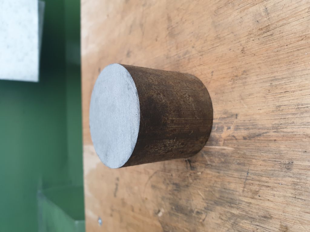
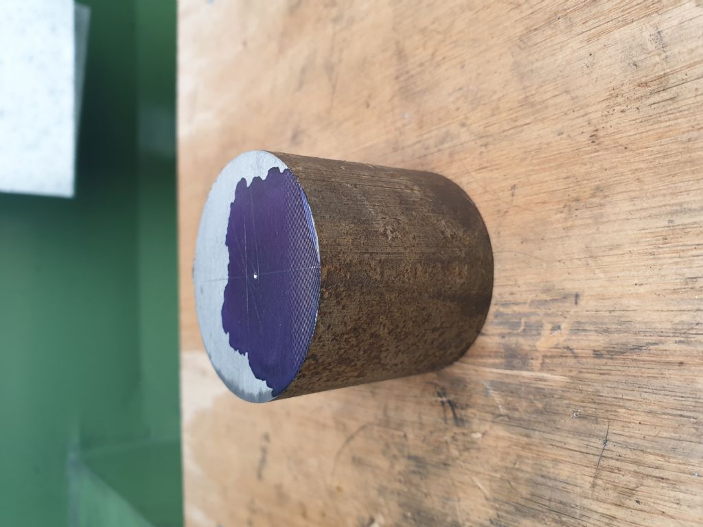
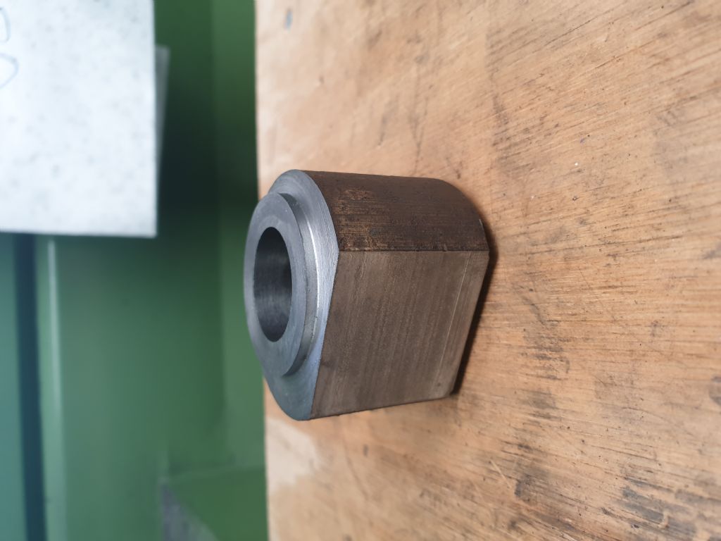
Iv'e never cut a cylinder from bar stock before, but seemingly "the process may look a bit daunting"
but "the process is quite simple" not for me!
he goes-
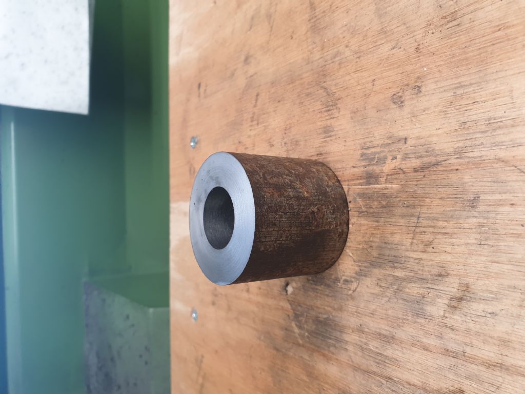
cut a hole
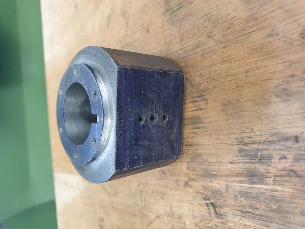
oh dear! port face won't be big enough
start again
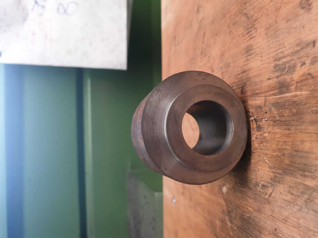
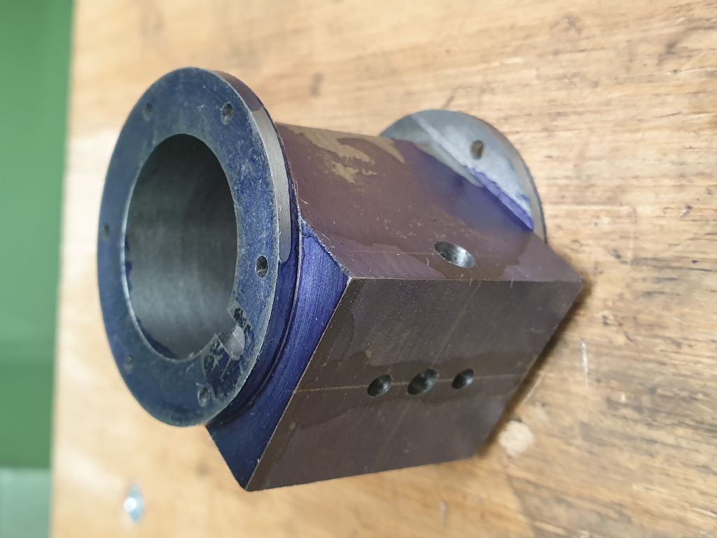
better
port face big enough
Ok it's not perfect port face is 0.2mm too wide and if you look close iv'e nicked the inside of the bottom flange, but that will be covered any how. so on the whole to say I've never done this before i'm quite pleased with the results, I'm going to leave the holes for the steam chest till later when I decide weather to make the chest 0.2mm wider or not. the exhaust is drilled but not tapped yet, a bit of fettling, honing and jobs a good un.
You are off to a good start, I doubt the 0.2mm will make a lot of difference so upto you if you make the chest and cover wider or to drawing.
I have just had a message from Lee to say that he can cast in most materials to your own supplied patterns. I've only had CI from him which was cleanly cast and a nice bit of iron to machine. Anyone with deep pockets and a liking for a bit of bling could ask for a bronze flywheel. he can be contacted by message on e-bay here
Hi Paul, nice work on the cylinder as Jason said that's a good start.
I'm following Jason's building methods but scaling his sizes down to approximately 3/4 full size.
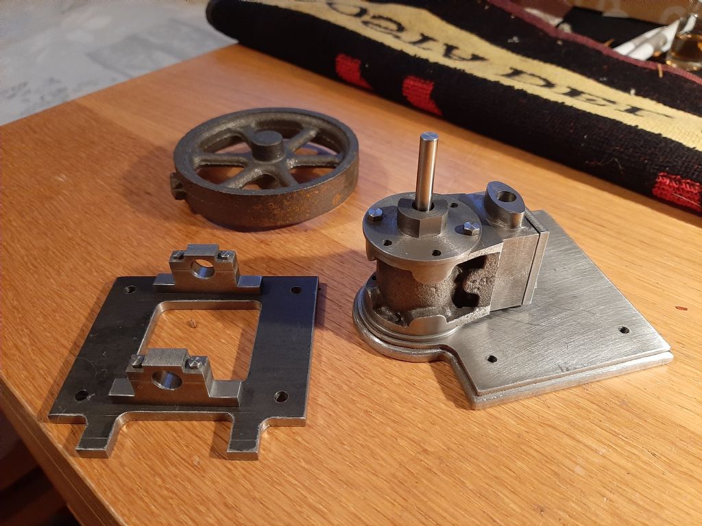
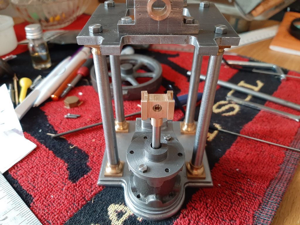
As I didn't have a suitable piece of cast iron in stock for the cylinder so I decided to treat myself to a 10v cylinder which is just about the right size at 19mm stroke and bore. Got that machined up and have made the valve chest to Jason.s design. Also made some progress on the bearing blocks which were tricky to make as they are quite small.
Still looking for a 3" flywheel and may use the 10v one which I have had for some time.
Jason I took note of your comments in the latest M.E. regarding the use of B.M.S. for the crosshead guides. It was a good point I assume the the cold roll steel is less stressed and thus not as liable to distort.
Once again some good machining ideas in the latest issue in particular the way you made the crankshaft.
Some mor egood progress there Geoff and good use of the casting, I would think that anyone building to my size may be able to make use of a Stuart No7 cylinder as there should be enough metal there for the slightly smaller bore or make it 25mm instead of 24mm.You don't want to believe everything you read in magazines that should have been HOT rolled as that does have less stress so not a slikely to distort as cold rolled (bright) bar.
Another option for those wanting curved spoke flywheels is to fabricate, Find's site has a good guide
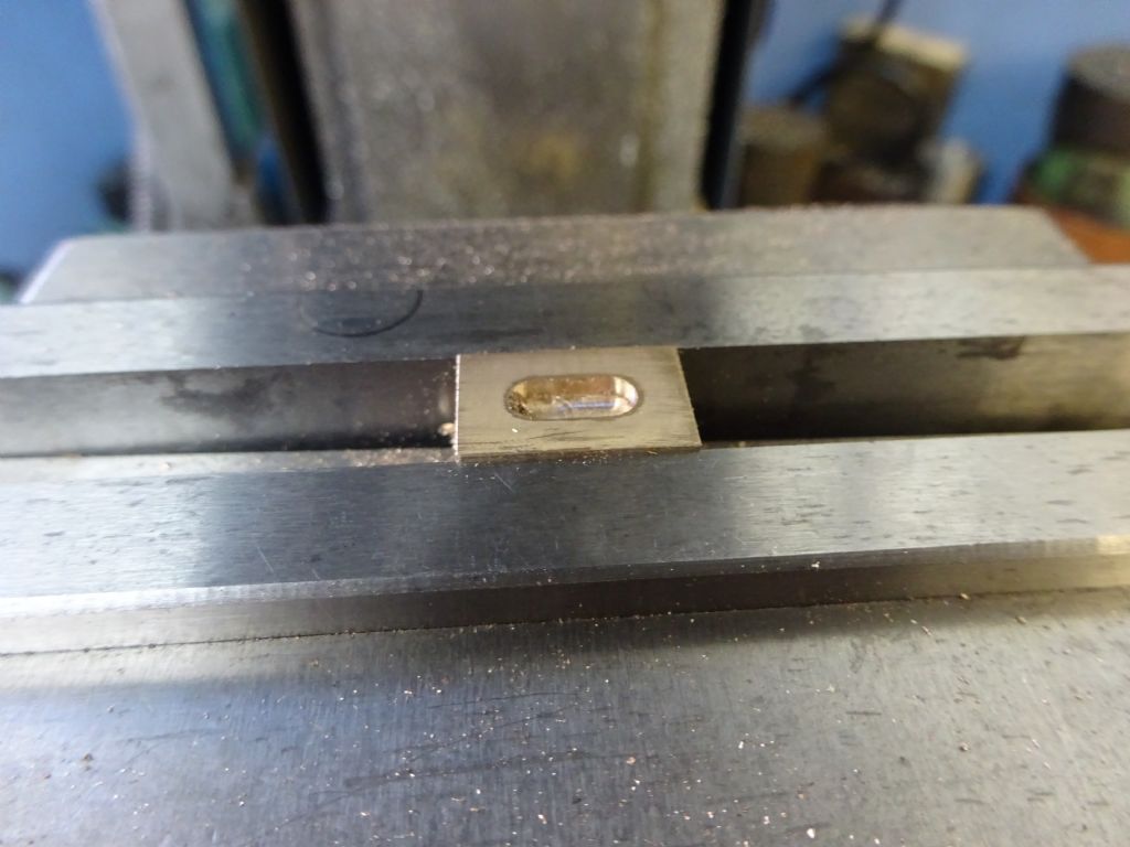
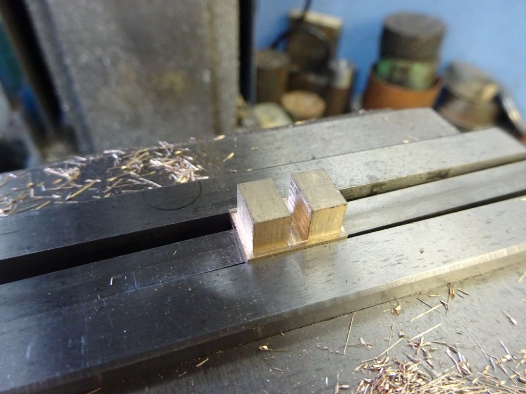
Held the other way up the slots for rod and nut can be added. If a vice stop is positioned before the part is removed from the vice after machining the recess you can put it back in and keep the X axis datum, Y still stays the same as fixed jaw will still locate the work in that axis.
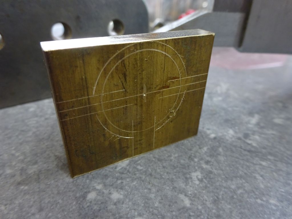
Marked out eccentric material to give a guide of where to machine to
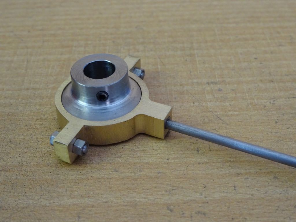
Completed eccentric strap, eccentric and rod. Note position of grub screw at the highest point of the eccentric which will help with setting the timing in the final part 7.
Welcome to the forum John, Are you having a go at making this one?
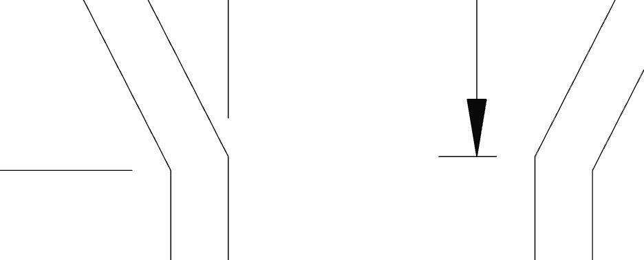
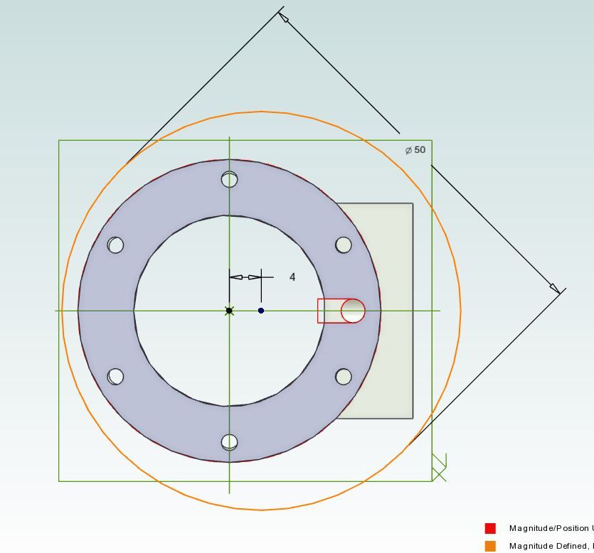
The two dimensions don't add up as one is to the internal corner and the other to the external as these are the extents of the two cuts I dimensioned it that way to give builders the sizes to cut. Will post a better detail later but this is the blown up drawing
Thanks. Yes I am up to issue 4620 but awaiting some cast iron. 60 Dia mm as far as I can see you can't get it out of 50mm. Where is the extract for the gland?
I am using a Wabeco CNC mill for some parts it makes things much easier.
It would have been helpful if you could have given a list of materials when the series started as where I live I have to order from a company 2000KMS AWAY and have to wait quite a while for delivery.
I think you'll find the guides are milled out of solid, you wouldn't be able to join then and get the strength required to resist movement whatever way you joined them.
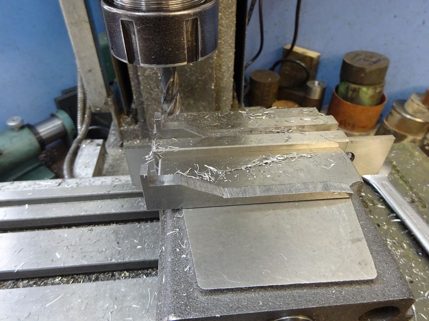
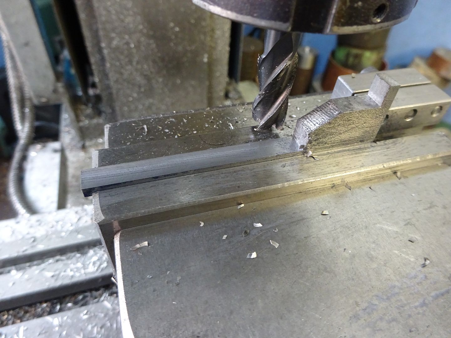
This is basically as described in the text but photos will be a bit bigger:
First machine your two pieces of 6mm thick material to the overall 79.5mm x 20.0mm, then mark out so you can saw away most of the waste.
Now hold in the vice with the inner face resting on parallels and mill down the 6.2mm leaving 3mm which forms the horizontal leg.
Hold the part again with the inner face resting on a parallel but use a thicker one this time and mill the outerface for a length of 55.3mm from the bottom of the part and again leave 3mm thickness of material to form the vertical leg.
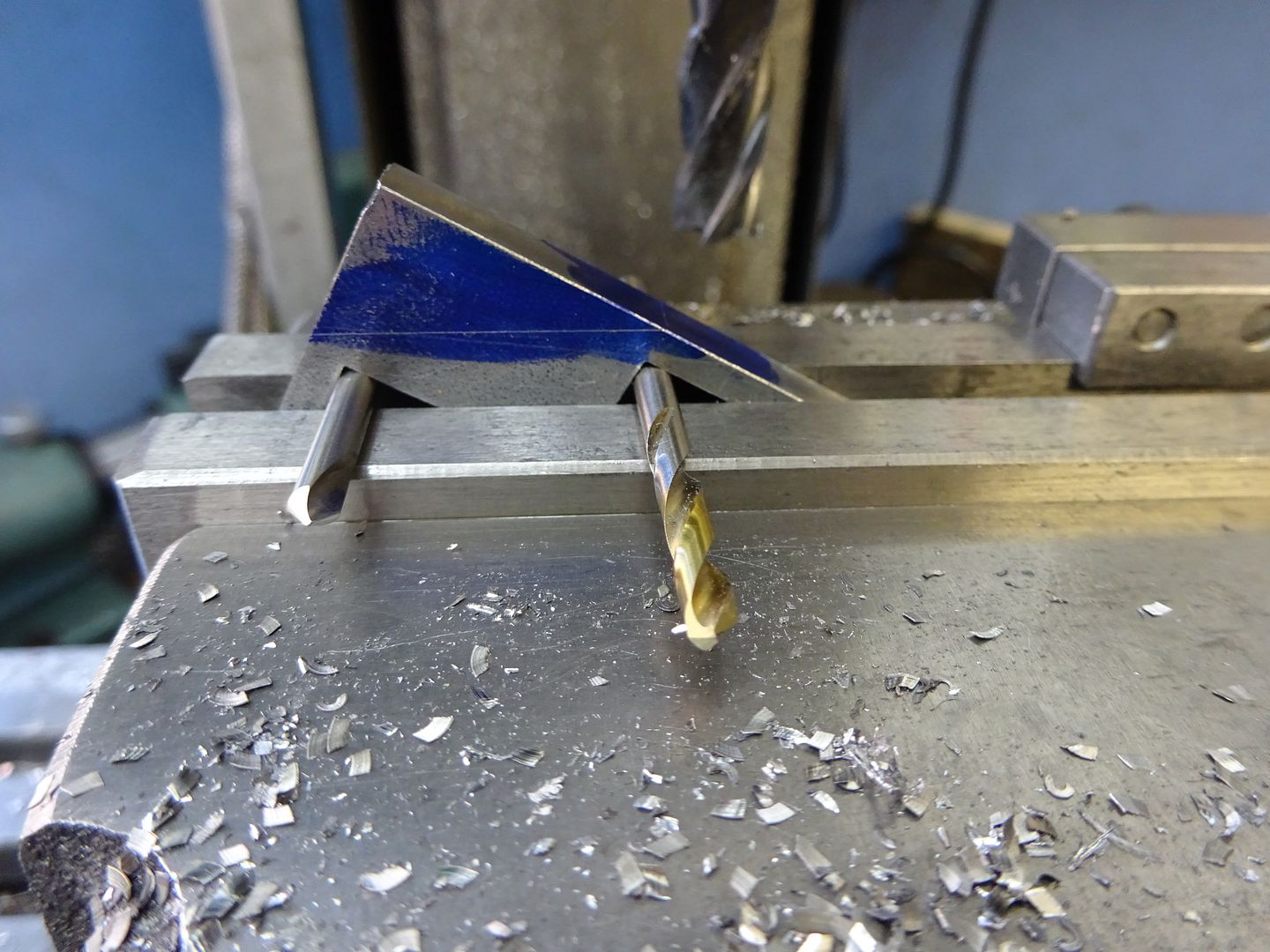
You can now blue the inner edge of the part and mark a line 23.5mm down which is just visible in the photo and I also carried a line around from that to show where the metal will be removed to but that is optional. Slip two matching diameter rods or drill bits onto the vice and use them to support the two internal corners machined in the earlier steps. This will hold the work at the correct angle so no measuring required, just machine down until the cutter is at the marked line on the side.
The final operation is to turn the part the other way up so the sloping face you just machined is resting on a parallel and mill out the remaining material to leave a 3mm finished thickness. No pic of that.
As for the cylinder that will indeed come out of 50mm stock as per the article, just offset the bore of teh cylinder, something like 4mm will do nicely and leave plenty to spare all round
John, I'm also just about to send you a message so look at the green bar along the top of the page and your "inbox" will be flashing, click that.
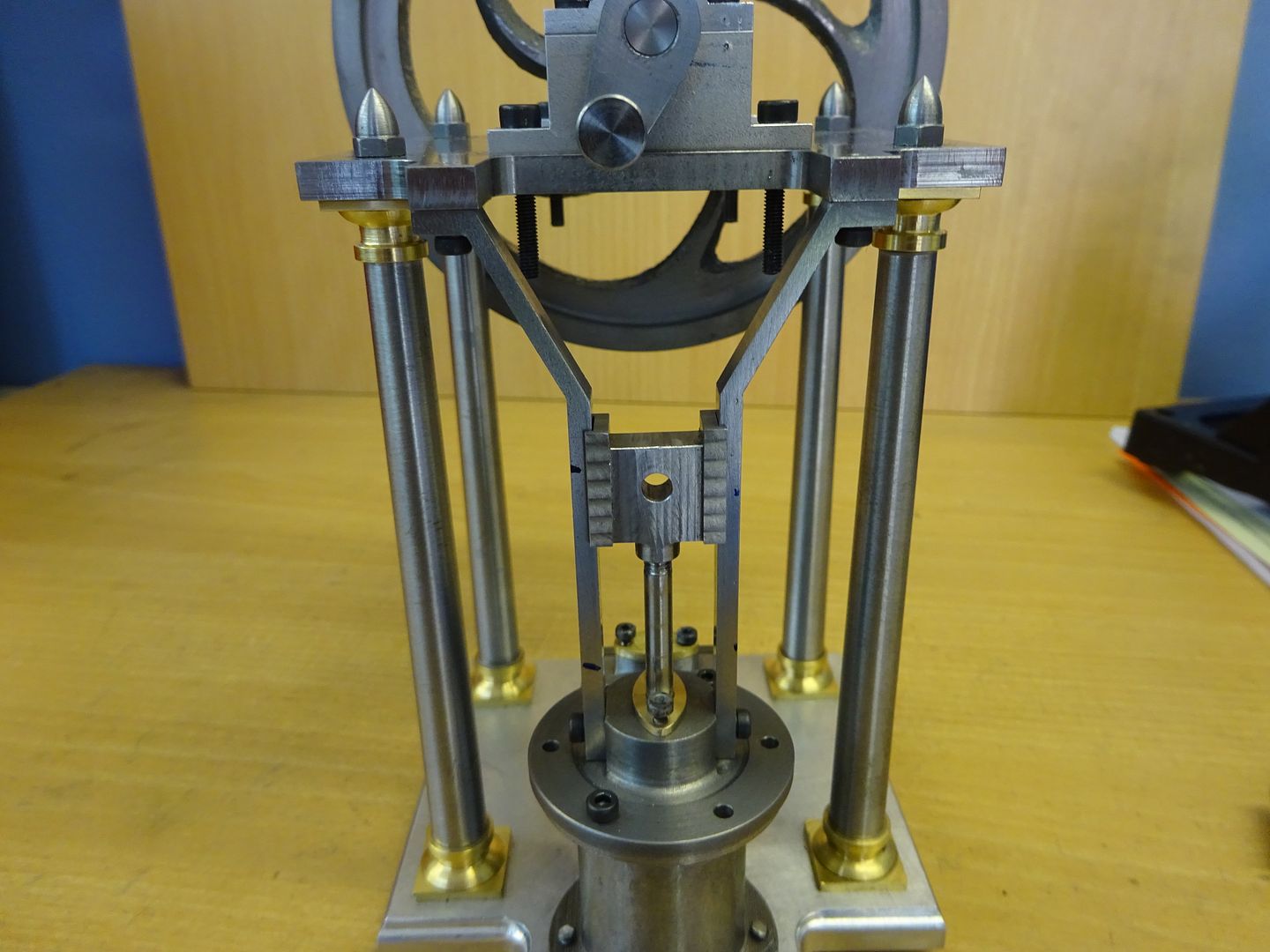
Jason I would be interested to know how you fixed the cross head guides in place. Not so much the actual fixings but how did you line everything up accurately.
Both guides have to be set accurately in the same vertical plane and also the centre line of each guide must be on the centre line of the cylinder.
I have thoughts on how to do it but would be interested in your method.
Geoff, I don't recall doing anything special when it came to fitting the parts together. Making the cross head on the end of a bar helps as you can drill and tap it and then by doing the milling with a spin indexer it should ensure all the milling ops are equal either side of the piston rod hole. likewise making sure you accurately locate the ctr of the cylinder cover and then take equal amounts off either side will ensure the two guides sit equally either side of the piston rod.
On the guides I did each milling operation on one and then the other using a vice stop to ensure both parts went into the vice in the same position as they were swapped in and out. Once complete a slight tweak in the vice and checking against a straight edge was needed as there was a little distortion.
Then it is just a case of checking for free movement as each piece is assembled so you can tell what makes it go tight rather than building it all up and then trying to trace where a tight spot may be. Don't know if you have noticed but I also specified M2.5 for the fixing in the entablature but went with a 3.0mm hole in the top of the guide which gives a bit of wiggle room should it be needed.
it is, I have no Ali in my scrap box. To be honest it's not something I use. besides it's expensive Last time I looked at the price of some, I nearly had a heart attack. There's a steel stock holder local to me and if you buy standard stock lengths it's dirt cheap so my efforts are all in steel.